Table of Contents

Related Manuals for OTIS GEN2 OI-6940 Notis Quad


Summary of Contents for OTIS GEN2 OI-6940 Notis Quad
- Page 1 Model OI-6940 Notis Quad 4-Gas Sensor Assembly __________________________________ Operation Manual Revision 2.0w ________________________________________________________________________________ ______________________________________________________...
-
Page 2: Product Overview
Class I, Division 1, Group C and D certified while in the field. Non-intrusive calibration is made possible by using an Otis Instruments, Inc. distributed magnet to activate the MENU, BACK, ADD, and SUB buttons. -
Page 3: Table Of Contents
Table of Contents Product Overview............................2 Introduction..............................4 Warnings..............................5 Complete System Diagram........................6 Complete System (External)...............................6 Terminal Board (Internal Diagram)..........................7 Battery Board (Internal Diagram).............................7 Button Functions................................8 Radio Transmission Information......................9 Power On (from Power Off Mode)......................10 Power Off ..............................12 Global Settings Menu Mode ........................ -
Page 4: Introduction
Introduction This document is an Operation Manual containing diagrams and step-by-step instruction for proper operation of the Otis Instruments, Inc. WireFree Model OI-6940 Notis Quad 4-Gas Sensor Assembly. This document should be read before initial operation of the product. Should a question arise during the use of the product, this document will serve as a first reference for consultation. If... -
Page 5: Warnings
However, if the enclosure lid is removed, for whatever reason, the OI-6940 Notis Quad certification is not valid. To avoid invalidating the certification, once the device is put in the field, always use the Otis Instruments, Inc. distributed magnet to ensure non-intrusive calibration. -
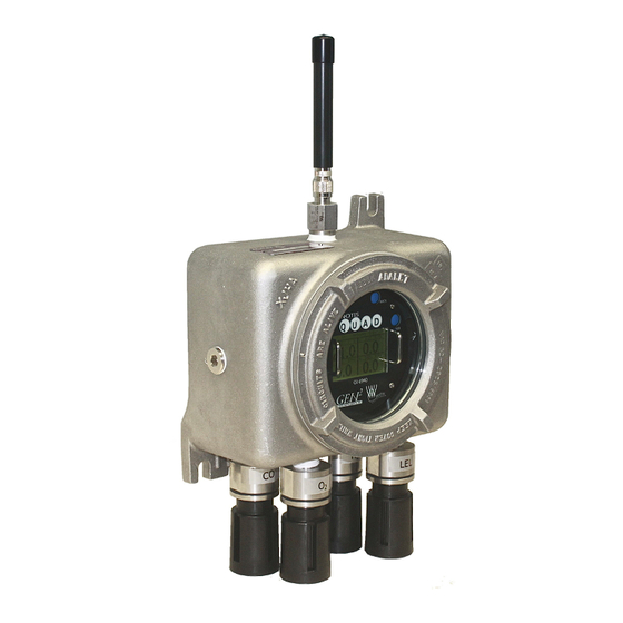
Page 6: Complete System Diagram
Complete System Diagram The following diagrams should be consulted for identification of the system and all parts that may be referred to in this Operation Manual. Complete System (External) -
Page 7: Terminal Board (Internal Diagram)
Terminal Board (Internal Diagram) Battery Board (Internal Diagram) -
Page 8: Button Functions
Button Functions When navigating through the Global Settings Menu Mode or Sensor Settings Menu Mode: touch ADD to advance to the next screen; touch SUB to return to the previous screen; touch MENU to select the displayed option (or, in cases when “BACK”... -
Page 9: Radio Transmission Information
Radio Transmission Information When the radio sends, it sends all sensors—starting with sensor 1—unless in Relay Test Mode. When in Relay ● Test Mode: the radio only sends the sensor that is in Relay Test Mode; the radio only sends when ADD or SUB are touched. -
Page 10: Power On (From Power Off Mode)
Powering on the device activates its functions. When powered on, the device is fully functional and access to system and settings menus is allowed. 1. Touch an Otis Instruments, Inc. distributed magnet to the ADD indicator label on the left side of the Notis Quad to activate ADD (and turn on the device). - Page 11 2. The Notis Quad will then countdown from 30 to 0. During the countdown, the Display Screen will scan through a series of logos, as well as continuously display sensor assembly information, as follows: From 60 to 45, the Display Screen will show the Otis Instruments, Inc. logo and unit information. ▪...
-
Page 12: Power Off
“Fault 9” for that sensor channel. 1. Touch and hold an Otis Instruments, Inc. distributed magnet against the right side of the Notis Quad for four seconds to activate SUB (and turn off the device). -
Page 13: Global Settings Menu Mode
Entering Global Settings Menu Mode 1. Touch and hold an Otis Instruments, Inc. distributed magnet against the MENU indicator label on the left side of the Notis Quad for approximately six seconds to active MENU and enter Global Settings Setup Mode. -
Page 14: Setting Network Id
Global Settings Menu Mode cont... 2. The Display Screen should resemble the following illustration: Setting Network ID 1. Touch the magnet to MENU to enter Global Settings Menu Mode. The display screen should resemble the following illustration: 3. Touch MENU (SELECT) to setup the Network I.D. Touch ADD (NEXT) to continue to the next Global Settings Menu Mode option. -
Page 15: Viewing The Info Screen
Global Settings Menu Mode cont... 4. The Display Screen should resemble the following illustration: 5. Touch ADD (increase) or SUB (decrease) to manipulate the Network I.D. Setting. NOTE: The Network I.D. may be set between 1 and 52 when using a 900 MHz, or between 1 and 78 when using a 2.4 GHz radio. -
Page 16: Setting Contrast
Global Settings Menu Mode cont... 2. Touch MENU (SELECT) to view the Info Screen. When viewing the Info Screen, the Display Screen should resemble the following illustration: NOTE: Touch ADD/SUB to turn the backlight On/Off while viewing the Info Screen. 3. -
Page 17: Return To Factory Default Settings
Global Setting Menu Mode cont... 2. Touch MENU (SELECT) to set the Contrast. The Display Screen should resemble the following illustration: 3. Touch ADD (increase) or SUB (decrease) to manipulate the Contrast Setting. NOTE: The contrast may be set between 0 and 255. If ADD or SUB is continuously touched, the number sequence will loop (e.g., If ADD is touched when the Display Screen shows “255”, the next number to appear will be “0”). - Page 18 Global Settings Menu Mode cont... 2. Touch MENU (SELECT) to select the “Return Default” screen. The Display Screen should resemble the following illustration: 3. Touch ADD (YES) to return to factory default; touch SUB (NO), MENU (BACK), or BACK (BACK) if no change is to be made.
-
Page 19: Sensor Settings Menu Mode
Entering Sensor Settings 1. Touch and hold an Otis Instruments, Inc. distributed magnet against the MENU indicator label on the left side of the Notis Quad for approximately six seconds to active MENU and enter Sensor Settings Menu Mode. -
Page 20: Sensor Settings Setup
Sensor Settings Menu Mode cont... 2. The Display Screen should resemble the following illustration: Sensor Settings Setup 1. Touch ADD (NEXT) to enter the Sensor Settings Menu Mode for Sensor 1. The Display Screen should resemble the following illustration: 2. Touch MENU (SELECT) to enter Sensor 1 Settings Setup. If no changes are needed for Sensor 1, touch ADD (NEXT) to advance to Sensor 2 Settings Setup (and continue to the next section of this operation manual). -
Page 21: Sensor On/Off Setting
Sensor On/Off Setting 1. Touch MENU (SELECT) to set the Sensor 1 On/Off setting; touch ADD (NEXT) to continue to the next menu option. 2. Touch ADD (ON) to turn Sensor 1 On. Touch SUB (OFF) to turn Sensor 1 Off. 3. -
Page 22: Sensor Null
Sensor Settings Menu Mode cont... NOTE: When a sensor is turned Off, the following menu items will not be available for setup, and the display screen will show “OFF” for that sensor when the Notis Quad is in Normal Operating Mode. In the following illustration, Sensor 1 is Off and Sensors 2, 3, and 4 are On (while in Normal Operating Mode). -
Page 23: Sensor Calibration (Cal)
Sensor Calibration (Cal) 1. Touch ADD (NEXT) to continue to the next setting: Sensor 1 Cal. 2. Touch ADD (NEXT) to continue to the next menu option. NOTE: This section of the Operation Manual is for Sensor Setup only. For Null and Calibration instructions, see the Calibration section of this operation manual. -
Page 24: Sensor Relay Test
Radio Address Setting cont... 3. If MENU was touched, the Display Screen should resemble the following illustration: 4. Touch ADD (increase) or SUB (decrease) to manipulate the Sensor 1 Radio Address setting. NOTE: When scrolling through the Radio Address Setting Options, address settings that are already in use will not be available. -
Page 25: Sensor Background Setting
Sensor Relay Test cont... 2. Touch MENU (SELECT) to begin the Sensor 1 Relay Test; touch ADD (NEXT) to continue to the next menu option. 3. If MENU was touched, the Display Screen should resemble the following illustration: 4. Touch ADD (increase) or SUB (decrease) to manipulate the Sensor 1 Relay Test setting (in increments of 1/20 the full sensor range) until the value is high enough to trigger the pre-set alarms. - Page 26 Sensor Background Setting cont... 2. Touch MENU (SELECT) to begin adjust the Sensor 1 Background Setting; touch ADD (NEXT) to continue to the next menu option. 3. Touch ADD (increase) or SUB (decrease) to manipulate the Sensor 1 Background Setting. NOTE: When using an O2 sensor, there will be a “Background High”...
-
Page 27: Sensor Cal Method
Sensor Cal Method 1. Touch ADD (NEXT) to continue to the next setting: Sensor 1 Cal Method. 2. Touch MENU (SELECT) to begin adjust the Sensor 1 Cal Method; touch ADD (NEXT) to continue to the next menu option. 3. If MENU was touched, the Display Screen should resemble one of the following illustrations: 4. -
Page 28: Sensor Info
Sensor Info 1. Touch ADD (NEXT) to continue to the next setting: Sensor 1 Info. 2. Touch MENU (SELECT) to view the Sensor 1 Info; touch ADD (NEXT) to continue to the next menu option. 3. If MENU was touched, the Display Screen should resemble the following illustration: NOTE: Touch ADD/SUB to turn the backlight On/Off while viewing the Sensor Info Screen. -
Page 29: Sensor Last Time Null/Cal
Sensor Last Time Null/Cal 1. Touch ADD (NEXT) to continue to the next setting: Sensor 1 Last Time Null/Cal. 2. Touch MENU (SELECT) to view the last time Sensor 1 was nulled and calibrated; touch ADD (NEXT) to continue to the next menu option. 3. -
Page 30: Sensor Return Null/Cal To Default
Sensor Return Null/Cal to Default 1. Touch ADD (NEXT) to continue to the next setting: Sensor 1 Return Null/Cal to Default. 2. Touch MENU (SELECT) to return Sensor 1's Null/Call to Default; touch ADD (NEXT) to continue to the next menu option. - Page 31 Sensor Return Null/Cal to Default... 5. If ADD (YES) was touched, the Display Screen will ask for confirmation (as shown below). Touch ADD (YES) or SUB (NO) to confirm or deny the option to return Sensor 1's Null/Cal to default. 6.
-
Page 32: Calibration
Nulling the Sensor 1. Touch and hold an Otis Instruments, Inc. distributed magnet against the MENU indicator label on the left side of the Notis Quad for approximately six seconds to active MENU and enter Menu Mode. - Page 33 Sensor Calibration cont... 2. Touch ADD (NEXT) once. The Display Screen should resemble the following illustration: 3. Touch MENU (SELECT) to select the Sensor 1 Settings Menu. NOTE: To Null Sensor 2, 3, or 4: touch ADD (NEXT) one, two, or three more times, then touch MENU. 4.
- Page 34 Sensor Calibration cont... 5. Touch MENU (SELECT) to Null Sensor 1. The Display Screen should resemble the following illustration: 6. If ADD (YES) is selected, the backlight will turn Off and the Display Screen will begin counting down from 12 to 0, as shown below.
- Page 35 Sensor Calibration cont... 7. Once Null is complete (successfully), the Display Screen should resemble the following illustration: If the Null was not successful, the Display Screen will show “F5 NULL Failed Check Sensor Voltage”. This fault will be displayed when one of the following instances occur: If the voltage is wrong when using a positive sensor, “F5”...
-
Page 36: Sensor Calibration (Manual Calibration)
Sensor Calibration (Manual Calibration) The Notis Quad may be Autocaled or Manually Caled. To choose the calibration method, see the Sensor Setup Menu Mode section of this Operation Manual. The following instructions are for Manual Calibration. For Automatic Calibration instructions, see the previous section of this Operation Manual. - Page 37 Sensor Calibration cont... 3. Replace the rainguard of the sensor being calibrated with an Otis OI-410 Calibration Cup. 4. Apply a known calibration gas to the OI-410 Calibration Cup that is attached to the sensor housing. 5. Touch MENU (SELECT) to calibrate (Cal) Sensor 6.
-
Page 38: Sensor Calibration (Automatic Calibration)
Sensor Calibration (Automatic Calibration) The Notis Quad may be Autocaled or Manually Caled. To choose the calibration method, see the Sensor Setup Menu Mode section of this Operation Manual. The following instructions are for Automatic Calibration. For Manual Calibration instructions, see the next section of this Operation Manual. - Page 39 Sensor Calibration cont... 4. Touch ADD (YES) to calibrate the sensor, or SUB (NO) to return to the Sensor 1 Cal screen. 5. If ADD (YES) was touched, the Display Screen should resemble the following illustration: 6. Touch ADD (YES) to calibrate the sensor, or SUB (NO) to return to the Sensor 1 Cal screen. 7.
- Page 40 10. Unscrew and remove the sensor rainguard from the sensor housing. 11. Replace the rainguard of the sensor that is being calibrated with an Otis OI-410 Calibration Cup. 12. Apply a known calibration gas to the OI-410 Calibration Cup that is attached to the sensor housing.
- Page 41 Sensor Calibration cont... 14. The sensor will be called when the timer countdown that is displayed on the screen reaches “0”. Countdown times for different gases are as follows: H2S, SO2, O2, CO, NH3, CH2O, NO2, O3 = 90 • seconds LEL = 120 seconds •...
- Page 42 Sensor Calibration cont... 16. Unscrew the OI-410 Calibration Cup. 17. Reattach (screw on) the sensor rainguard to the sensor housing.
-
Page 43: Battery Replacement
Note: Replacement of the battery should be done in a non-classified environment, where no explosive gas is present. The Notis Quad uses an Otis Lithium Ion 76AH battery-pack with connector. New batteries should only be obtained from Otis Instruments, Inc. or an affiliated distributor. - Page 44 NOTE: Do not use any metal object to help remove the Front Panel. NOTE: Do not remove any connecting wires. 4. Gently lay the Front Panel to the side of the Notis Quad so that the battery-pack inside the Otis enclosure is visible.
- Page 45 Battery Replacement cont... 7. Squeeze the left and right sides of the Battery-Pack Input and pull the Battery-Wire Plug straight out of the Battery-Wire Input. 8. Slide the new battery's Battery-Wire Plug into the Battery-Pack Input. 9. Place the new battery on the Battery Board and secure it in place by screwing the Notis Quad's Battery Mount Strip back onto the Battery Board.
-
Page 46: Sensor Replacement
Failed alarm tests could be an indicator of the Notis Quad needing a sensor(s) replaced. 1. Power off the device by touching and holding an Otis Instruments, Inc. distributed magnet against the SUB indicator label on the right side of the Notis Quad for four seconds to activate SUB. - Page 47 Sensor Replacement cont... 3. With the sensor housing cap removed, the visible sensor will resemble the following illustration: 4. Using the thumb and forefinger, slide the sensor out of the Notis Quad. NOTE: Do not use any metal object to remove the sensor. NOTE: Be careful to not remove the sensor board when removing the sensor.
-
Page 48: Antenna Replacement
Otis Instruments, Inc. approved 2.4 GHz or 900 MHz antenna. 1. Power off the device by touching and holding an Otis Instruments, Inc. distributed magnet against the SUB indicator label on the right side of the Notis Quad for four seconds to activate SUB (which turns off device). - Page 49 Antenna Replacement cont... 3. Unscrew the current Antenna Connector from the Antenna Fitting. 4. Screw the new Antenna onto the Antenna Fitting. 5. Power on the device by touching the magnet to ADD.
- Page 50 OI-6940 Notis Quad Troubleshooting Guide Fault 4 • Reason: The Notis Quad's analog sensor board not responding Solution: Ensure that the analog board is properly connected; replace analog sensor board if still in Fault __________________________________________________________________________________________________ Fault 5 • Indicator: F5 NULL Failed Check Sensor Voltage Reason: 1.
-
Page 51: Specifications
Specifications Number of Sensors: 2-4 (1 Low-Power Infrared) Sensor Type: Electrochemical or Low-Power Infrared Battery Type: 3.6V 76 Amp Hour Battery-pack Battery Life: Up to 6 months Gases: H2S, O2, SO2, CL2, H2, NH3, CO, LEL (hydrocarbons), and more Remote Sensors: Kit to remote-mount the sensors 10, 25, 50, 75, or 100 feet from the enclosure Radio Type:... - Page 52 Battery All batteries supplied by Otis Instruments, Inc. are covered, from ship date, under a 90-day warranty. The OI-6940 Notis Quad battery warranty is only valid when using up to 1 LEL and 3 Electrochemical sensors on a properly functioning OI-...
- Page 53 Otis Instruments, Inc. Corporate Office 2200 E. Villa Maria Dr. Bryan, TX 77802 979.776.7700 www.otisinstruments.com...
Need help?
Do you have a question about the GEN2 OI-6940 Notis Quad and is the answer not in the manual?
Questions and answers