
Related Manuals for OTIS GenII WireFree OI-6900


Summary of Contents for OTIS GenII WireFree OI-6900
- Page 1 Model OI-6900 Sensor Assembly __________________________________ Operation Manual Revision 2.3w ________________________________________________________________________________ ______________________________________________________...
-
Page 2: Product Overview
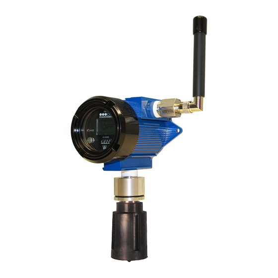
The Otis Instruments, Inc. GenII WireFree OI-6900 ambient air gas sensor assembly is a WireFree gas sensor assembly that uses an electro- chemical sensor element to detect a variety of gases. The device comes standard with a 102 x 64 graphical LCD screen, Otis Instruments standard three-button interface, Otis-blue custom explosion-proof enclosure, non-intrusive magnetic switches, and radio (900MHz or 2.4GHz). -
Page 3: Table Of Contents
Table of Contents Product Overview............................2 Introduction..............................4 Warnings..............................5 Complete System Diagram........................6 Complete System (External)...............................6 Complete System (Internal)............................... 7 Power On (from Power Off Mode)......................8 Power Off ..............................10 Normal Operating Mode......................... 12 Basic Menu Mode ............................ 13 Calibration.............................. -
Page 4: Introduction
Introduction This document is an Operation Manual containing diagrams and step-by-step instruction for proper operation of the Otis Instruments, Inc. WireFree Model OI-6900 Sensor Assembly. This document should be read before initial operation of the product. Should a question arise during the use of the product, this document will serve as a first reference for consultation. If... -
Page 5: Warnings
Instruments, Inc. distributed magnet. However, if the Moore lid is removed, for whatever reason, the OI-6900 certification is not valid. To avoid invalidating the certification, once the device is put in the field, always use the Otis Instruments, Inc. distributed magnet to ensure non-intrusive calibration. -
Page 6: Complete System Diagram
Complete System Diagram The following diagrams should be consulted for identification of the system and all parts that may be referred to in this Operation Manual. Complete System (External) -
Page 7: Complete System (Internal)
Complete System (Internal) -
Page 8: Power On (From Power Off Mode)
1. Locate ADD on the Front Panel. 2. Touch an Otis Instruments, Inc. distributed magnet to the left side of the device to activate ADD (and turn on the device). NOTE: When the magnet touches the device and a connection has been made a trapezoid will appear. - Page 9 Power On cont... 3. The device will then count down from 60 to 0. From 60 to 30, the Display Screen will show the Otis Instruments, Inc. logo. From 30 to 0, the Display Screen should resemble the following illustration: ...
-
Page 10: Power Off
“Fault 9” for that sensor channel. 1. Locate SUB on the Front Panel. 2. Touch and hold an Otis Instruments, Inc. distributed magnet against the right side of the device for four seconds to activate the SUB button (which turns the device off). - Page 11 Power off cont... 3. When powering off, the display screen will switch from showing “0” to “OFF”. The display will continue to show “OFF” (when power is being supplied to the unit) until the device is powered on.
-
Page 12: Normal Operating Mode
Normal Operating Mode When powered on, the device will enter and remain in Normal Operating Mode until commanded otherwise. The presence of gas will affect the transmission of signals to the receiving controller in the following ways. When the device is in Normal Operating Mode, and there is no gas present, the sensor will send a message to the ●... -
Page 13: Basic Menu Mode
Calibration Mode (instead of the screen that was last displayed). Nulling the Sensor NOTE: When using an O2 sensor, the nulled reading will be 20.9. 1. Touch an Otis Instruments, Inc. distributed magnet against the top side of the device to active MENU and enter Setup Mode. - Page 14 Nulling the Sensor cont... 2. Touch the magnet to MENU once. 3. The display screen should resemble the following illustration: NOTE: A message will be sent to the receiving controller indicating that the sensor is in Null Mode.. 4. As the Display Screen instructs, press ADD to auto null. 5.
- Page 15 Nulling the Sensor cont... 6. Press ADD for “yes” or SUB for “no”. NOTE: If too much time elapses between when ADD is pressed and when the question regarding clean air is answered, the device will default back to the primary Null screen. If this occurs, simply press ADD again. 7.
-
Page 16: Calibration (Auto Cal)
NOTE: When using the Auto Cal method, the calibration gas should be less than full scale of the sensor. 1. After the Null has been set (see above), touch an Otis Instruments, Inc. distributed magnet to the top side of the device to activate the MENU button. - Page 17 Calibration cont... 4. The display screen should resemble the following illustration: 5. Touch the magnet to ADD (“Yes”) for the device to begin Auto Cal, or SUB (“No”) to return to Normal Operating Mode. NOTE: If “Yes” is chosen, the device will be calibrated. To stop calibration after this point, the battery must be unplugged.
- Page 18 Calibration cont... 7. The %LEL displayed on the screen should match that of the calibration bottle. Touch the magnet to ADD to increase the reading displayed on the screen by 1% LEL, or SUB to decrease. 8. Once the %LEL displayed on the screen matches that of the calibration bottle, touch the magnet to MENU. 9.
- Page 19 Calibration cont... 11. Replace the sensor rainguard with an Otis OI-410 Calibration Cup. 12. Apply a known calibration gas to the OI-410 Calibration Cup that is attached to the sensor housing. 13. Touch the magnet to MENU. 14. The display screen should resemble the following illustration, counting down to begin Auto Cal.
-
Page 20: Calibration (Manual Cal)
Calibration (Manual Cal) 1. After the Null has been set (see above), touch an Otis Instruments, Inc. distributed magnet to the top side of the device to activate the MENU button. 2. The display screen should resemble the following illustration:... - Page 21 3. Unscrew and remove the sensor rainguard from the sensor housing. 4. Replace the sensor rainguard with an Otis OI-410 Calibration Cup. 5. Apply a known calibration gas to the OI-410 Calibration Cup that is attached to the sensor housing.
- Page 22 Setting Calibration cont... 8. Touch the magnet to ADD (increase) or SUB (decrease) to manipulate the reading on the display screen to match that of the calibration gas. EXAMPLE: If the calibration gas is 25 PPM and the number on the display screen is 22 PPM, touch the magnet to ADD approximately three times.
-
Page 23: Setting Radio Address
To ensure proper communication with the receiving monitor, set the Sensor Address to match the one assigned to this Sensor Assembly at the monitor. 1. After Calibration is complete (see above), touch an Otis Instruments, Inc. distributed magnet to the top side of the device to activate the MENU button. - Page 24 3. Press ADD to increase, or SUB to decrease, the Radio Address setting. 4. Once the Radio Address is set, touch an Otis Instruments, Inc. distributed magnet to the top side of the device to activate the MENU button (to exit Basic Menu Mode).
-
Page 25: Advanced Menu Mode
Relay Test Mode. 1. While the device is in Normal Operating Mode, Touch and hold an Otis Instruments, Inc. distributed magnet against the top side of the device for approximately six seconds to active MENU and enter the Advanced Menu Mode. -
Page 26: Setting Network Id
To ensure proper communication with the receiving monitor, set the Network ID to match the one assigned to the monitor. 1. After the Relay/Alarms Test is complete (see above), touch an Otis Instruments, Inc. distributed magnet to the top side of the device to activate the MENU button. -
Page 27: Diagnostics
The diagnostics screen allows the user to view the Radio Status, Battery Voltage (Power), and Sensor Voltage. 1. After the Network ID is set (see above), touch an Otis Instruments, Inc. distributed magnet to the top side of the device to activate the MENU button. -
Page 28: Last Setup Times
The Unit Info screen allows the user to view the date and serial number of the unit. 1. After the Last Setup Times have been viewed (see above), touch an Otis Instruments, Inc. distributed magnet to the top side of the device to activate the MENU button. -
Page 29: Background Gas Setting
“BackgroundH”. When the background reading is below the Background Low setting—or above Background High setting—the unit will transmit every five seconds. 1. After the Unit Info has been viewed (see above), touch an Otis Instruments, Inc. distributed magnet to the top side of the device to activate the MENU button. -
Page 30: Calibration Method Setting
4. Once the Calibration Method has been set, continue to the next step. Setting LCD Contrast 1. After the Calibration Method Setting has been set (see above), touch an Otis Instruments, Inc. distributed magnet to the top side of the device to activate MENU. -
Page 31: Restore To Factory Default
4. Once the Contrast has been set, continue to the next step. Restore to Factory Default 1. After the Contrast has been set (see above), touch an Otis Instruments, Inc. distributed magnet to the top side of the device to activate MENU. - Page 32 Restore to Factory Default cont... 3. Touch the magnet to ADD for “Yes” or SUB for “No”. Factory Default Settings are: Background Gas set at 4% of full scale • Network ID set at 5 • Sensor Radio Address set at 1 •...
- Page 33 Restore to Factory Default cont... 6. The device is now in Normal Operating Mode. NOTE: If the OI-6900 was reset to factory default, repeat the configuration steps, as well as re-null and re-calibrate the device.
-
Page 34: Battery Replacement
NOTE: Replacement of the battery should be done in a non-classified environment, where no explosive gas is present. The device uses an Otis size “D” Lithium 19AH battery with connector. New batteries should only be obtained from Otis Instruments, Inc. or an affiliated distributor. - Page 35 Battery Replacement cont... 3. Using only your fingers, pull straight up on the Front Panel Thumb-Screws until the unit is removed from the standing eyelets. NOTE: Do not use any metal object to help remove the Front Panel. NOTE: Do not remove any connecting wires. 4.
- Page 36 Battery Replacement cont... 7. Squeeze the top and bottom of the Battery-Wire Plug, located in the Battery-Wire Socket on the Circuit Board. 8. Pull the Battery-Wire Plug straight out of the Battery-Wire Socket. 9. Place the new battery's plug in the socket. 10.
- Page 37 Battery Replacement cont... 14. Place the Moore enclosure lid on top of the Moore enclosure base. 15. Rotate the lid until it is tightly screwed in place (approximately 20 rotations). 16. Power on the device and check the battery voltage to ensure that the new battery is fully functional and at 3.6 volts.
-
Page 38: Sensor Replacement
CAUTION: THE INTERNAL COMPONENTS CAN BE STATIC SENSITIVE. USE CAUTION WHEN OPENING THE ENCLOSURE AND HANDLING INTERNAL COMPONENTS. 1. Power off the device by touching and holding an Otis Instruments, Inc. distributed magnet against the right side of the device for four seconds to activate SUB. - Page 39 Sensor Replacement cont... 3. With the sensor housing cap removed, the visible sensor will resemble the following illustration: 4. Using the thumb and forefinger, slide the sensor out of the device. NOTE: Do not use any metal object to remove the sensor. NOTE: Be careful to not remove the sensor board when removing the sensor.
-
Page 40: Antenna Replacement
Otis Instruments, Inc. approved 2.4 GHz or 900 MHz antenna. 1. Power off the device by touching and holding an Otis Instruments, Inc. distributed magnet against the right side of the device for four seconds to activate SUB (which turns off device). - Page 41 Antenna Replacement cont... 3. Screw the new Antenna onto the Antenna Fitting. 4. Power on the device by touching the magnet to ADD. NOTE: When the magnet touches the device and a connection has been made a trapezoid will appear.
-
Page 42: Appendix A: O2 Sensor Information
Appendix A: O2 Sensor Information... -
Page 43: Null
O2 Sensor Information OI-6900 Sensor Assemblies for sensing O2 gas will perform differently than other OI-6900 Sensor Assemblies. The following items are variance that OI-6900 Sensor Assemblies for sensing O2 gas will have from other OI-6900 Sensor Assemblies. Null When Nulled, the reading will be 20.9. Background Gas Setting Two background setting modes will be available—Low and High. -
Page 44: Appendix B: Oi-6900 Troubleshooting Guide
Appendix B: OI-6900 Troubleshooting Guide... - Page 45 OI-6900 Troubleshooting Guide Fault 4 (F4) Reason: The top card is losing communication to the analog sensor board Indication: On OI-6000-X units, F4 means that the Analog to Digital Conversion (ADC) on the analog sensor board is not communicating to the digital sensor board. Solution: Check the orientation of the analog sensor board and/or try a new analog sensor board.
- Page 46 Fault 14 (F14) Reason: The unit cannot see the Primary Monitor. NOTE: This fault only occurs on sensor assemblies that contain a radio. Solution: Refer to the solutions provided for F9. Also, make sure the Primary is “On” and that the Network I.D. on the Primary is the same as this unit.
-
Page 47: Specifications
Interface: Three push buttons (MENU, ADD, SUB); three corresponding magnetic, non-intrusive switches; non-intrusive calibration Enclosure: Otis-Blue explosion/flame-proof Certifications: CSA certified, Class 1, Div I, Groups C and D Ex d IIB, Zone 1 Aex d IIb Warranty: Hardware: One year (limited) - Page 48 Warranty Statement for WireFree Model OI-6900 Hardware Otis Instruments, Inc. (Manufacturer) warrants its products to be free of defects in workmanship and materials—under normal use and service—from the date of purchase from the manufacturer or from the product's authorized reseller. The hardware for this device is under a one-year limited warranty.
- Page 49 Otis Instruments, Inc. 301 S Texas Ave. Bryan, TX 77803 Service Department: 903.566.1300 Corporate Office: 979.776.7700 service@otisinstruments.com www.otisinstruments.com...
Need help?
Do you have a question about the GenII WireFree OI-6900 and is the answer not in the manual?
Questions and answers