Table of Contents
Advertisement
Advertisement
Table of Contents

Related Manuals for MultiWave Sensors Smart Aligner

Summary of Contents for MultiWave Sensors Smart Aligner
- Page 1 USERS GUIDE V1.1 January 2015...
-
Page 2: Table Of Contents
Section 10 Tool LCD Display........................11 Section 11 User Menu........................... 12 Section 12 Viewing the Diagnostic and Information Menu..............12 Section 13 Mobile Device App "Smart Aligner..................13 13.1 Smart Aligner App Flow......................13 13.2 App Detailed Description......................14 13.3 Quick Measure........................14 13.4 Site Survey.......................... -
Page 3: Section 1 Introduction
The Smart Aligner System is a GPS-based compass designed to effectively and efficiently align antennas in real time. The Smart Aligner Tool provides a True North or Grid North Azimuth measurement, Tilt, Roll and Position. Once the Tool is mounted to the antenna using the Universal Mounting Bracket, the Tool is simply turned on. From there the user interface is the full feature App on any iOS or Android smart device. -
Page 4: Section 4 What's In The Case
Wall Charger: For charging the Smart Aligner Tool. Car Charger: For charging the Smart Aligner Tool. NOTE: Throughout this Guide the “Smart Aligner Tool” will be referred to as the “Tool” The “Universal Mounting Bracket” will be referred to as the “Bracket”... -
Page 5: Section 5 Tool Description
Tool Description Short Arm Long Arm Charging Port User Interface Tether Line/Pin Data/Laser Port Mounting Dowel Pins (underside) Mounting Screw Knob Short Arm: Contains first GPS antenna. From stored position: Rotates to +90° and 180° OR -90° and 180° Long Arm: Contains Second GPS antenna. From stored position: Stored position to +90° OR Stored Position to -90° Charging Port: Port for Wall or Car Charger User Interface : LCD Screen, Menu Buttons and Power Button Tether Line/Pin: Attaches to Bracket... -
Page 6: Section 6 Arm Positions
Ratchet Strap with hook: Strap goes around the front of the antenna and hook is attached to the Fastening Pins Dowel Pin Receptacles: The two Mounting Dowel Pins on the Smart Aligner Tool mate to two Dowel Pin Receptacles on the Bracket. The Tool can be attached Front or Back or Right/Left. -
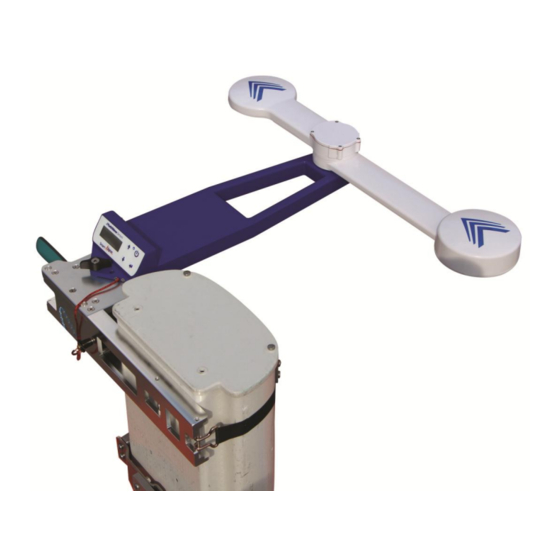
Page 7: Section 8 Bracket Attached To The Antenna
Bracket Attached to the Antenna The Bracket is shown mounted on the right side of the antenna to be aligned. The Bracket can also be mounted on the left side of the antenna. The four Dowel Pin Receptacles on the Bracket allow for attaching the Tool facing Front, Back or Right. -
Page 8: Section 9 Tool Attached To The Bracket
Tool Attached to the Bracket The Tool and Bracket can be attached to the antenna in 18 different configurations. The 18 configurations are: Right or Left side of antenna: Tool facing Front on Bracket, Arms Forward Right or Left side of antenna: Tool facing Front on Bracket, Arms Left T (shown below) Right or Left side of antenna: Tool facing Front on Bracket, Arms Right T Right or Left side of antenna: Tool facing Right on Bracket, Arms Forward 9-10 Right or Left side of antenna: Tool facing Right on Bracket, Arms Left T... -
Page 9: The 18 Configurations
The 18 Configurations No matter which configuration the Tool and Bracket are mounted to the antenna the Antenna Azimuth will be compensated. The user does not need to set any offsets. Sensors in the Bracket and Tool detect the configuration and automatically compensate the Azimuth, Tilt and Roll of the antenna. -
Page 10: Procedure To Attach The Tool To The Bracket
Procedure to attach the Tool to the Bracket Example is for Right side of antenna: Tool facing Front, Arms Left T 1. Tether the Tool to the Bracket 2. Line up the Mounting Dowel Pins (underside of Tool) to the Dowel Pin Receptacles on the Bracket 3. -
Page 11: Section 10 Tool Lcd Display
Tool LCD Display When the Tool is turned on in the folded position it starts with the message “Position Arms” that indicates that the arms need to be deployed to one of the arm positions. Once the arms are deployed the message “Starting Solution” appears and an azimuth solution is being calculated. -
Page 12: Section 11 User Menu
User Menu To view the User Interface Menu press the Menu Enter button Scroll through the menu using the Up/Down buttons There will be a > next to the selected menu item. Press the Menu Enter button to toggle the selection. Use the Up/Down buttons to continue through the menu. -
Page 13: Section 13 Mobile Device App "Smart Aligner
Antenna Alignment closeout reports. The user installs the App from either the App Store or Google Play by searching for “smart aligner multiwave”. The App is free. Described here is the iOS App. The Android and iOS Apps are identical in operation and look but may be different with respect to the gestures offered by the different operating systems. -
Page 14: App Detailed Description
13.2 App Detailed Description This section will describe the different screens and features available on the App. After the end of this section there will be a step by step guide for the user to follow to get familiar with the App. There are some advanced features in the App that will be described in the Advanced Features section. -
Page 15: Site Survey
Site Survey 13.4 Screen 1 Screen 2 After Pressing “Site Survey” in Main Screen After Pressing “+” in Screen 1 Create/Add a Site. A screen and keyboard will be displayed to enter the Site name Refers to the number of antennas within the Site. - Page 16 Screen 5 Screen 6 After Pressing the sec:1 pos:1 Antenna After Pressing “Align” in Screen 5 Press “Align” The “Align Antenna” screen will be displayed. The user aligns the antenna based on the target information entered. Once the user has aligned the antenna to the Carrier accuracy required the user is...
- Page 17 Screen 8-Scroll Down Screen 9 After tapping “AGL Height” The ”AGL Height” can be entered manually here. If using the optional Laser Rangefinder then tap “Laser” . The keyboard will disappear. Connect the Laser Rangefinder, aim to the ground and take a shot. The Tool will automatically calculate the AGL and will be...
- Page 18 Screen 12 Screen 13 After tapping the Camera icon Up to four pictures can be taken Take a picture and to store the image tap “Use” Scroll through the images that have been taken. Up to four pictures can be taken and saved to the report.
- Page 19 Screen 16 Screen 17 After tapping “Report”, “Select all” in the Antenna list After tapping “Report All in Screen 16 The following antennas within “Site1” (example) will be included in the report. The report can now be emailed See next page for an example of a report Screen 19 Screen 18...
-
Page 20: Report Example
13.5 Report example... -
Page 21: Settings
Settings 13.6 Screen 1 Simulation Mode Units will be converted for: Elevation AGL Height DMS : Degrees Minutes Seconds for Latitude and Longitude. Decimal Degrees is default When Simulation mode is on this will be red. App must be RESTARTED when toggling Simulation Mode SIMULATION will be displayed... -
Page 22: Section 14 Advanced App Features
This option allows the user or RF engineer to enter the antenna information into a csv file. The csv file can then be emailed and directly imported into the Smart Aligner App. The user imports the file and the Antenna Setup information is populated. -
Page 23: Csv File Description
csv File Description 14.3 The csv has eighteen (18) User entered fields and twenty one (21) Measurement fields. The User fields are entered by the User and the Measurement fields are automatically populated after an alignment and verification. 14.4 USER Entered Values FIELD FORMAT Integer... -
Page 24: Measurement Values
Measurement Values 14.5 FIELD FORMAT Date D/M/Y Time h:m:s Measured Azimuth Decimal degrees (0 to 360) Azimuth Type T (True North) or G (Grid North) Measured Mechanical Tilt Decimal degrees (-90 to 90) Measured Mechanical Roll Decimal degrees (-90 to 90) Latitude Decimal degrees or DMS Direction... -
Page 25: Import A Csv Site File
For example see entered data example as below. Email “office.csv” to your phone. Tap and hold “office.csv” in the attachment and there will be an option to “Open in Smart Aligner” Tap “Open in Smart Aligner”... -
Page 26: Azimuth Tolerance
Enter the remaining data (not required) Save the file. See NOTE above. Import the csv file to Smart Aligner. See Import a csv Site file ( section 14.1) Set the Tool so that it is pointing at 213 degrees (as an example) and tap “Verify”... -
Page 27: Laser Rangefinder Measurement For Agl (Option)
Laser Rangefinder Measurements for AGL (Option) 14.9 The AGL of the antenna can be measured using Laser Rangefinder and this measurement can flow directly through the Tool. The Tool will automatically determine the Vertical Distance (VD) and display the value on the App and on the Tool. -
Page 28: Section 15 Charging The Tool
Tool will shut off. There are five indicator bars that each represent two hours of operation. When there is just one bar left the App will show it in red. Only use the supplied chargers or those recommended by Multiwave Sensors. A wall and car charger are included with the system. -
Page 29: Section 16 Optional Brackets
Optional Brackets There are some antennas that the Bracket is not suited for. Those antennas either have non-flat backplanes, are odd shapes or have flanges that could interfere with the bracket. We have therefore designed several brackets and adapters so as to easily mount to these type of antennas. 16.1 Ericsson AIR 21 Bracket The Ericsson AIR 21 antennas shape and form factor require a custom bracket to be used with the Tool to ensure... -
Page 30: Gogo Bracket
16.2 GOGO Bracket The Gogo network utilizes an antenna with side fins that do not work well with the flexible strap. We have design a specific Gogo Bracket for that antenna, which is to be used instead of the Bracket. The Gogo Bracket can be stored in the accessory bay in the case. -
Page 31: Dish Adapter
Dish Adapter 16.3 Microwave Dishes come in all shapes and sizes. It would be impossible to make one bracket that would address every dish on the market. Since each job usually has a similar dish, we recommend that you fabricate a bar that spans the front face of the dish and then mount the Dish Adapter on one end. -
Page 32: Section 17 Specifications
12 lb (5.4 kg) TOTAL WEIGHT : 20 lb (9.1 kg) Communication Ports LED backlit display: User interface and display Wi-Fi: Smart Aligner to user’s mobile device Connectivity: Smartphone/Tablet – iOS or Android Cable interface: Serial RS-232 Reporting Report formats:... -
Page 33: Section 18 Troubleshooting
There were some earlier bugs that caused crashes. The most common one was using extended characters or a Comma in the “Antenna Setup” fields. SOLUTION: Update and install the newest Smart Aligner App version. Do not use extended characters or Commas in the Antenna Setup fields. -
Page 34: Section 19 Contact, Warranty, Repair And Rma
Extended warranties are available. Contact MWS or one of MWS’s authorized distributors for more information. Repair and Return Information If the Smart Aligner System needs to be returned to MWS for any repair you will need to request an RMA #. Please email the following information to info@multiwavesensors.com...
Need help?
Do you have a question about the Smart Aligner and is the answer not in the manual?
Questions and answers