Table of Contents
Advertisement
Advertisement
Table of Contents

Related Manuals for Avid CNC PRO 60120 Series


Summary of Contents for Avid CNC PRO 60120 Series
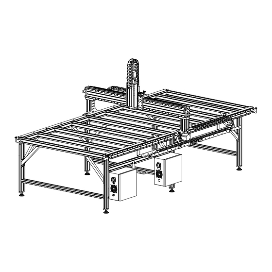
- Page 1 PRO Series 60120 5' x 10' CNC Machine Kit Assembly Instructions Version 2020Q1.2...
- Page 2 Machine revision notes will list any information that may have changed in a machine revision. A machine purchase date will be given to help determine if these apply to your machine. Version 2020Q1.2 PRO60120 © 2020 Avid CNC Assembly Instructions All Rights Reserved...
- Page 3 7. Throughout the assembly of your machine, you will use Roll-in T-Nuts. Review the instructions below for proper use of this component. 8. Heavy-duty cardboard packaging tubes are used to safely ship gear rack and profile linear rails. Tips are provided below for opening these packaging tubes. Version 2020Q1.2 PRO60120 © 2020 Avid CNC Assembly Instructions All Rights Reserved...
-
Page 4: Roll-In T-Nuts
Roll-in T-Nuts Assembly steps will depict Roll-in T-Nut installation as shown above. Version 2020Q1.2 PRO60120 © 2020 Avid CNC Assembly Instructions All Rights Reserved... - Page 5 To install in the appropriate extrusion slot, position the T-Nut as indicated. Version 2020Q1.2 PRO60120 © 2020 Avid CNC Assembly Instructions All Rights Reserved...
- Page 6 Insert the T-Nut into the extrusion slot and rotate 90°. Version 2020Q1.2 PRO60120 © 2020 Avid CNC Assembly Instructions All Rights Reserved...
- Page 7 When properly installed, the indicated face of the T-Nut will be parallel with the face of the extrusion. Assembly Note A small allen wrench can be inserted into the hole of the T-Nut and subsequently used to rotate it the full 90°. Version 2020Q1.2 PRO60120 © 2020 Avid CNC Assembly Instructions All Rights Reserved...
- Page 8 Cardboard Packaging Tubes Cardboard Packaging Tube Cardboard packaging tubes will contain gear rack and profile linear rails. Take care when opening to prevent damage to these components. Version 2020Q1.2 PRO60120 © 2020 Avid CNC Assembly Instructions All Rights Reserved...
- Page 9 20mm (3/4") Utility Knife Use a utility knife (or similar tool) to cut the cardboard 20mm (3/4") from either end of the tube. Version 2020Q1.2 PRO60120 © 2020 Avid CNC Assembly Instructions All Rights Reserved...
-
Page 10: Tools List
Metric Combination Wrenches: - 8mm, 10mm, 13mm, 16mm, 17mm Metric Tape Measure Threadlocker (Loctite Blue 242) Dimensional Lumber (refer to Step 1.2.3.4) (2) 24" Hand Trigger Clamp Cable Ties Version 2020Q1.2 PRO60120 © 2020 Avid CNC Assembly Instructions All Rights Reserved... -
Page 11: Section 1: Base Assembly
Section 1: Base Assembly Version 2020Q1.2 PRO60120 © 2020 Avid CNC Assembly Instructions All Rights Reserved... - Page 12 1.1 Table Leg Assembly Section Note Skip to Section 1.3 if you are not using an Avid CNC leg kit Version 2020Q1.2 PRO60120 © 2020 Avid CNC Assembly Instructions All Rights Reserved...
-
Page 13: Parts And Tools Required
Remaining parts from this kit used in future sections Required Tools: - 6mm Ball-End Allen Wrench - Adjustable Wrench - Tape Measure Recommended Additional Tools: - 6mm Hex Ball-End Power Bit - 13mm Combination Wrench Version 2020Q1.2 PRO60120 © 2020 Avid CNC Assembly Instructions All Rights Reserved... - Page 14 40 Series Anchor Fastener M8 Roll-in T-Nut 4080 Leg Crossmember Extrusion, 1550mm (61") Thread the socket head cap screws into the t-nuts through the anchor fasteners as indicated. Version 2020Q1.2 PRO60120 © 2020 Avid CNC Assembly Instructions All Rights Reserved...
- Page 15 1.1.1.2 Slide the anchor assemblies into the 1550mm (61") 4080 leg crossmember extrusion. Version 2020Q1.2 PRO60120 © 2020 Avid CNC Assembly Instructions All Rights Reserved...
- Page 16 1.1.1.3 Repeat the previous steps to install anchor fasteners on both sides of the 1550mm (61") leg crossmember extrusions. Version 2020Q1.2 PRO60120 © 2020 Avid CNC Assembly Instructions All Rights Reserved...
- Page 17 1.1.1.4 4080 Leg Extrusion, 750mm (29-1/2") Repeat the previous steps to install anchor fasteners on one side of each 750mm (29-1/2") leg extrusion. Version 2020Q1.2 PRO60120 © 2020 Avid CNC Assembly Instructions All Rights Reserved...
- Page 18 Install a foot assembly onto each 750mm (29-1/2") leg extrusion as indicated. Assembly Note It is recommended to first install the foot plate onto the extrusion before threading in the leveling foot. Version 2020Q1.2 PRO60120 © 2020 Avid CNC Assembly Instructions All Rights Reserved...
- Page 19 Assembly Note Initially thread the leveling feet all of the way into the foot plate. After machine assembly, final adjustments will be made in table leveling procedure. (www.avidcnc.com/leveling-squaring-and-tramming-your-cnc-machine-p-438.html) Version 2020Q1.2 PRO60120 © 2020 Avid CNC Assembly Instructions All Rights Reserved...
- Page 20 1.1.3 Leg Crossmember Assembly 1.1.3.1 Use a section of 1550mm (61") leg crossmember extrusion to join two of the 750mm (29-1/2") leg extrusion sections. Version 2020Q1.2 PRO60120 © 2020 Avid CNC Assembly Instructions All Rights Reserved...
- Page 21 1.1.3.2 165mm (6-1/2") Position the leg crossmember 165mm (6-1/2") from the bottom of the leg as indicated. Version 2020Q1.2 PRO60120 © 2020 Avid CNC Assembly Instructions All Rights Reserved...
- Page 22 For tightening the anchor fasteners, an M6 ball-end allen wrench is required. An M6 ball-end driver attachment for a drill or impact driver can make assembly more efficient. Version 2020Q1.2 PRO60120 © 2020 Avid CNC Assembly Instructions All Rights Reserved...
- Page 23 1.1.4 Leg Gussets Installation 1.1.4.1 M8 x 14mm Hex Cap Bolt M8 Roll-in T-Nut CRP813-01 Leg Kit Gusset Install M8 bolts through the gusset as indicated, partially threading on the t-nuts. Version 2020Q1.2 PRO60120 © 2020 Avid CNC Assembly Instructions All Rights Reserved...
- Page 24 Slide the gusset into the extrusion as indicated and partially tighten the M8 bolts. Assembly Note The top of the gusset should be roughly flush with the top of the extrusion. Version 2020Q1.2 PRO60120 © 2020 Avid CNC Assembly Instructions All Rights Reserved...
- Page 25 One gusset should be lowered to the dimension shown to accommodate the electronics mounting bar. The dimension shown is measured from the bottom of the foot plate to the bottom of the gusset. Version 2020Q1.2 PRO60120 © 2020 Avid CNC Assembly Instructions All Rights Reserved...
- Page 26 Repeat the previous steps to assemble the remaining gussets and extrusion sections in the indicated configuration. Assembly Note There will be two lowered gussets at the indicated positions. All remaining gussets are flush with the top of the leg extrusion. Version 2020Q1.2 PRO60120 © 2020 Avid CNC Assembly Instructions All Rights Reserved...
- Page 27 1.1.5 Electronics Mounting Bar Installation 1.1.5.1 M8 Roll-in T-Nut M8 x 14mm Hex Cap Screw On the indicated gussets, install M8 bolts and partially thread on the t-nuts. Version 2020Q1.2 PRO60120 © 2020 Avid CNC Assembly Instructions All Rights Reserved...
- Page 28 4080 Electronics Bar Extrusion, 1480mm (58-1/4") Separate the leg assemblies with lowered gussets to allow room for the 1480mm (58-1/4") electronics bar extrusion to slide on the lower gussets. Version 2020Q1.2 PRO60120 © 2020 Avid CNC Assembly Instructions All Rights Reserved...
- Page 29 1.1.5.3 Slide the electronics bar onto the gussets, leaving space between it and the leg extrusions as indicated. Version 2020Q1.2 PRO60120 © 2020 Avid CNC Assembly Instructions All Rights Reserved...
- Page 30 1.1.5.4 Slide assembled anchor fasteners into the leg extrusions, positioning them above and below the electronics bar as indicated. Version 2020Q1.2 PRO60120 © 2020 Avid CNC Assembly Instructions All Rights Reserved...
- Page 31 1.1.5.5 With the electronics bar flush against the leg extrusion, insert the anchor fasteners. Version 2020Q1.2 PRO60120 © 2020 Avid CNC Assembly Instructions All Rights Reserved...
- Page 32 1.1.5.6 Complete this process on both sides of the electronics bar. Tighten all electronics bar anchor fasteners. Version 2020Q1.2 PRO60120 © 2020 Avid CNC Assembly Instructions All Rights Reserved...
- Page 33 1.2 Table Frame Assembly (with Leg Kit) Version 2020Q1.2 PRO60120 © 2020 Avid CNC Assembly Instructions All Rights Reserved...
-
Page 34: Parts And Tools Required
- Tape Measure Recommended Additional Tools: - 6mm Hex Ball-End Power Bit - 13mm Combination Wrench - Dimensional Lumber (refer to Step 1.2.3.4) - (2) 24" Hand Trigger Clamp Version 2020Q1.2 PRO60120 © 2020 Avid CNC Assembly Instructions All Rights Reserved... - Page 35 1.2.1 Frame Extrusions Installation 1.2.1.1 4080 Frame Extrusion, 1750mm (68-7/8") Slide two of the 1750mm (68-7/8") frame extrusions onto the leg assemblies as indicated. Version 2020Q1.2 PRO60120 © 2020 Avid CNC Assembly Instructions All Rights Reserved...
- Page 36 1.2.1.2 Bring the ends of the frame extrusion flush with the legs as indicated. Fully tighten the anchor fasteners attaching the frame extrusions to the two outside legs. Version 2020Q1.2 PRO60120 © 2020 Avid CNC Assembly Instructions All Rights Reserved...
- Page 37 1.2.1.3 1560mm (61-7/16") Position the leg assemblies 1560mm (61-7/16") apart as indicated. Assembly Note The dimension shown is measured from the front edge of the leg extrusion. Version 2020Q1.2 PRO60120 © 2020 Avid CNC Assembly Instructions All Rights Reserved...
- Page 38 1.2.1.4 Partially tighten the fasteners at the indicated locations. Version 2020Q1.2 PRO60120 © 2020 Avid CNC Assembly Instructions All Rights Reserved...
- Page 39 1.2.1.5 CRP810-02 Splice Bar M6 x 10mm Set Screw Install two splice bars into the end of one of the frame extrusions as indicated. Version 2020Q1.2 PRO60120 © 2020 Avid CNC Assembly Instructions All Rights Reserved...
- Page 40 1.2.1.6 Position the splice bars as shown and tighten the indicated set screws. Version 2020Q1.2 PRO60120 © 2020 Avid CNC Assembly Instructions All Rights Reserved...
- Page 41 1.2.1.7 4080 Frame Extrusion, 1750mm (68-7/8") Slide a 1750mm (68-7/8") frame extrusion onto the splice bars as indicated. Version 2020Q1.2 PRO60120 © 2020 Avid CNC Assembly Instructions All Rights Reserved...
- Page 42 Tighten the indicated set screws. Assembly Note While the assembly will stand upright in the absence of applied force, be careful not to tip the assembly over. Version 2020Q1.2 PRO60120 © 2020 Avid CNC Assembly Instructions All Rights Reserved...
- Page 43 1.2.1.9 Install the remaining leg assembly as indicated. Version 2020Q1.2 PRO60120 © 2020 Avid CNC Assembly Instructions All Rights Reserved...
- Page 44 1.2.1.10 260mm (10-1/4") Position the rear leg assembly 260mm (10-1/4") from the end of the frame extrusion as indicated. Version 2020Q1.2 PRO60120 © 2020 Avid CNC Assembly Instructions All Rights Reserved...
- Page 45 1.2.1.11 Use the remaining splice kits to install the other 1750mm (68-7/8") frame extrusion on the other side of the frame. Version 2020Q1.2 PRO60120 © 2020 Avid CNC Assembly Instructions All Rights Reserved...
- Page 46 4080 Crossmember Extrusion, 1550mm (61") M8 x 30mm Socket Head Cap Screw 40 Series Anchor Fastener Thread the socket head cap screws into the anchor fasteners as indicated. Version 2020Q1.2 PRO60120 © 2020 Avid CNC Assembly Instructions All Rights Reserved...
- Page 47 1.2.2.2 Slide the anchor assembly into the extrusion. Version 2020Q1.2 PRO60120 © 2020 Avid CNC Assembly Instructions All Rights Reserved...
- Page 48 1.2.2.3 Loosely thread the double t-nuts onto the socket head cap screws as indicated. Version 2020Q1.2 PRO60120 © 2020 Avid CNC Assembly Instructions All Rights Reserved...
- Page 49 1.2.2.4 Repeat the previous steps on both sides for all ten of the crossmember extrusion pieces. Version 2020Q1.2 PRO60120 © 2020 Avid CNC Assembly Instructions All Rights Reserved...
- Page 50 1.2.3 Table Crossmembers Installation 1.2.3.1 Slide the t-nuts into the frame extrusion as indicated. Version 2020Q1.2 PRO60120 © 2020 Avid CNC Assembly Instructions All Rights Reserved...
- Page 51 1.2.3.2 Repeat the previous step for all crossmembers. Version 2020Q1.2 PRO60120 © 2020 Avid CNC Assembly Instructions All Rights Reserved...
- Page 52 Position the remaining crossmembers 360mm (14-3/16") apart (or 400mm (15-3/4") center to center), as indicated. Assembly Note Use dimensional lumber to help position the crossmembers, as shown in the following steps. Version 2020Q1.2 PRO60120 © 2020 Avid CNC Assembly Instructions All Rights Reserved...
- Page 53 Dimensional Lumber: Cut to length of 360mm (14-3/16") Cut two pieces of dimensional lumber (a 2x4 is recommended) to a length of 360mm (14-3/16"). Position this piece between the crossmembers as indicated. Version 2020Q1.2 PRO60120 © 2020 Avid CNC Assembly Instructions All Rights Reserved...
- Page 54 With the cut piece of lumber flush against the frame extrusion, clamp the crossmembers together. Assembly Note Recommended clamps are 24" Hand Trigger Clamps available at your local hardware store. Version 2020Q1.2 PRO60120 © 2020 Avid CNC Assembly Instructions All Rights Reserved...
- Page 55 1.2.3.6 Repeat this process to clamp the other side of the crossmember. While clamped, tighten the crossmember anchor fasteners. Version 2020Q1.2 PRO60120 © 2020 Avid CNC Assembly Instructions All Rights Reserved...
- Page 56 The rear crossmember will be positioned flush against the end of the frame extrusion. Assembly Note The rear crossmember will have a different spacing due to the length of the machine. Version 2020Q1.2 PRO60120 © 2020 Avid CNC Assembly Instructions All Rights Reserved...
- Page 57 M8 Roll-in T-Nut For each of the six gussets that attach to the table crossmembers, install two Roll-in T-Nuts to the bottom of the crossmember extrusion as indicated. Version 2020Q1.2 PRO60120 © 2020 Avid CNC Assembly Instructions All Rights Reserved...
- Page 58 1.2.3.9 Slide the t-nuts in the extrusion to align them with the gusset holes. Version 2020Q1.2 PRO60120 © 2020 Avid CNC Assembly Instructions All Rights Reserved...
- Page 59 1.2.3.10 M8 x 14mm Hex Cap Screw Insert the fasteners as indicated and partially tighten. Version 2020Q1.2 PRO60120 © 2020 Avid CNC Assembly Instructions All Rights Reserved...
- Page 60 After squaring the table, tighten all anchor fasteners and leg gusset fasteners. Assembly Note Position of the leg gussets may need to be adjusted in the table squaring process. Version 2020Q1.2 PRO60120 © 2020 Avid CNC Assembly Instructions All Rights Reserved...
- Page 61 1.3 Table Frame Assembly (without Leg Kit) Section Note Skip this section if you are using an Avid CNC leg kit Version 2020Q1.2 PRO60120 © 2020 Avid CNC Assembly Instructions All Rights Reserved...
-
Page 62: Parts And Tools Required
- 6mm Ball-End Allen Wrench - Tape Measure Recommended Additional Tools: - 6mm Hex Ball-End Power Bit - Dimensional Lumber (refer to Step 1.3.2.4) - (2) 24" Hand Trigger Clamp Version 2020Q1.2 PRO60120 © 2020 Avid CNC Assembly Instructions All Rights Reserved... - Page 63 4080 Frame Extrusion, 1750mm (68-7/8") 4080 Frame Extrusion, 1750mm (68-7/8") Install set screws in the CRP810-02 splice bar. Join two pieces of 1750mm (68-7/8") frame extrusion using the splice bar as indicated. Version 2020Q1.2 PRO60120 © 2020 Avid CNC Assembly Instructions All Rights Reserved...
- Page 64 1.3.1.2 Bring the ends of the two extrusion pieces tight against each other. Tighten the set screws in BOTH splice bars. Version 2020Q1.2 PRO60120 © 2020 Avid CNC Assembly Instructions All Rights Reserved...
- Page 65 1.3.1.3 Use this process to form two spliced extrusion sections. Version 2020Q1.2 PRO60120 © 2020 Avid CNC Assembly Instructions All Rights Reserved...
- Page 66 4080 Crossmember Extrusion, 1550mm (61") M8 x 30mm Socket Head Cap Screw 40 Series Anchor Fastener Thread the socket head cap screws into the anchor fasteners as indicated. Version 2020Q1.2 PRO60120 © 2020 Avid CNC Assembly Instructions All Rights Reserved...
- Page 67 1.3.2.2 Slide the anchor assembly into the extrusion. Version 2020Q1.2 PRO60120 © 2020 Avid CNC Assembly Instructions All Rights Reserved...
- Page 68 1.3.2.3 Loosely thread the double t-nuts onto the socket head cap screws as indicated. Version 2020Q1.2 PRO60120 © 2020 Avid CNC Assembly Instructions All Rights Reserved...
- Page 69 1.3.2.4 Repeat the previous steps on both sides for all ten crossmember extrusion pieces. Version 2020Q1.2 PRO60120 © 2020 Avid CNC Assembly Instructions All Rights Reserved...
- Page 70 1.3.3 Table Crossmember Installation 1.3.3.1 Slide the t-nuts into the spliced frame extrusion as indicated. Version 2020Q1.2 PRO60120 © 2020 Avid CNC Assembly Instructions All Rights Reserved...
- Page 71 1.3.3.2 Repeat the previous step for all crossmembers. Version 2020Q1.2 PRO60120 © 2020 Avid CNC Assembly Instructions All Rights Reserved...
- Page 72 1.3.3.3 Position the outer crossmembers flush with the ends of the frame extrusion. Version 2020Q1.2 PRO60120 © 2020 Avid CNC Assembly Instructions All Rights Reserved...
- Page 73 Position the remaining crossmembers 360mm (14-3/16") apart (or 400mm (15-3/4") center to center), as indicated. Assembly Note Use dimensional lumber to help position the crossmembers, as shown in the following steps. Version 2020Q1.2 PRO60120 © 2020 Avid CNC Assembly Instructions All Rights Reserved...
- Page 74 Dimensional Lumber: Cut to length of 360mm (14-3/16") Cut two pieces of dimensional lumber (a 2x4 is recommended) to a length of 360mm (14-3/16"). Position this piece between the crossmembers as indicated. Version 2020Q1.2 PRO60120 © 2020 Avid CNC Assembly Instructions All Rights Reserved...
- Page 75 With the cut piece of lumber flush against the frame extrusion, clamp the crossmembers together. Assembly Note Recommended clamps are 24" Hand Trigger Clamps available at your local hardware store. Version 2020Q1.2 PRO60120 © 2020 Avid CNC Assembly Instructions All Rights Reserved...
- Page 76 1.3.3.7 Repeat this process to clamp the other side of the crossmember. While clamped, tighten the crossmember anchor fasteners. Version 2020Q1.2 PRO60120 © 2020 Avid CNC Assembly Instructions All Rights Reserved...
- Page 77 The rear crossmember will be positioned flush against the end of the frame extrusion. Assembly Note The rear crossmember will have a different spacing due to the length of the machine. Version 2020Q1.2 PRO60120 © 2020 Avid CNC Assembly Instructions All Rights Reserved...
- Page 78 Measure diagonal across the table in each direction as indicated. Make adjustments until the two measurements are within 1/8" or less of each other. After squaring the table, tighten all crossmember anchor fasteners. Version 2020Q1.2 PRO60120 © 2020 Avid CNC Assembly Instructions All Rights Reserved...
- Page 79 1.4 Linear Rail & Gear Rack Installation Section Note The remaining sections are applicable both with or without an Avid CNC leg kit. Some figures are shown without a leg kit for illustrative purposes. Version 2020Q1.2 PRO60120 © 2020 Avid CNC...
-
Page 80: Parts And Tools Required
- (1) Needle Tip Adapter Machine Revision Machines purchased prior to mid-February 2020 will use the following gear rack: (QTY: 4) Gear Rack, 1320mm (52") (QTY: 2) Gear Rack, 660mm (26") Version 2020Q1.2 PRO60120 © 2020 Avid CNC Assembly Instructions All Rights Reserved... - Page 81 Required Tools: - 4mm Allen Wrench - 5mm Allen Wrench - 6mm Allen Wrench - (2) Clamps - Tape Measure Version 2020Q1.2 PRO60120 © 2020 Avid CNC Assembly Instructions All Rights Reserved...
- Page 82 1.4.1 Linear Rail Assembly 1.4.1.1 Linear Rail, 1900mm (74-3/4") M5 Slide-in T-Nut M5 x 20mm Socket Head Cap Screw Thread fasteners into a 1900mm (74-3/4") linear rail as indicated. Version 2020Q1.2 PRO60120 © 2020 Avid CNC Assembly Instructions All Rights Reserved...
- Page 83 1.4.1.2 Linear Rail, 1600mm (63") Linear Rail, 1900mm (74-3/4") Repeat this step for each of the indicated linear rails. Version 2020Q1.2 PRO60120 © 2020 Avid CNC Assembly Instructions All Rights Reserved...
- Page 84 Slide one of the 1600mm (63") linear rails into the frame extrusion from the back of the machine. Assembly Note Use the upper t-slot on the frame extrusion as indicated. Version 2020Q1.2 PRO60120 © 2020 Avid CNC Assembly Instructions All Rights Reserved...
- Page 85 1.4.1.4 Back of Machine Position this 1600mm (63") linear rail at the back of the machine. Version 2020Q1.2 PRO60120 © 2020 Avid CNC Assembly Instructions All Rights Reserved...
- Page 86 1.4.1.5 Front of Machine Linear Rail, 1900mm (74-3/4") From the front of the machine, slide a 1900mm (74-3/4") linear rail into the frame extrusion. Version 2020Q1.2 PRO60120 © 2020 Avid CNC Assembly Instructions All Rights Reserved...
- Page 87 1.4.1.6 The ends of the linear rails should be roughly flush with the ends of the frame extrusion. Version 2020Q1.2 PRO60120 © 2020 Avid CNC Assembly Instructions All Rights Reserved...
- Page 88 1.4.2 Linear Rail Alignment 1.4.2.1 M8 x 25mm Socket Head Cap Screw Rail Alignment Jig M8 Roll-in T-Nut Attach the rail alignment jig to the extrusion as indicated. Version 2020Q1.2 PRO60120 © 2020 Avid CNC Assembly Instructions All Rights Reserved...
- Page 89 1.4.2.2 Fully tighten the alignment jig fasteners. Version 2020Q1.2 PRO60120 © 2020 Avid CNC Assembly Instructions All Rights Reserved...
- Page 90 1.4.2.3 Clamp the end of the linear rail to the jig as indicated. Version 2020Q1.2 PRO60120 © 2020 Avid CNC Assembly Instructions All Rights Reserved...
- Page 91 1.4.2.4 Repeat these steps with the second alignment jig at the linear rail splice. Version 2020Q1.2 PRO60120 © 2020 Avid CNC Assembly Instructions All Rights Reserved...
- Page 92 1.4.2.5 Tighten Fasteners on Clamped Rail Only Fully tighten the fasteners of the clamped rail. Version 2020Q1.2 PRO60120 © 2020 Avid CNC Assembly Instructions All Rights Reserved...
- Page 93 1.4.2.6 Ensure the rails are flush at the splice and leave the alignment jig clamped at this location. Version 2020Q1.2 PRO60120 © 2020 Avid CNC Assembly Instructions All Rights Reserved...
- Page 94 1.4.2.7 Move the other alignment jig to the opposite end of the machine. Version 2020Q1.2 PRO60120 © 2020 Avid CNC Assembly Instructions All Rights Reserved...
- Page 95 1.4.2.8 Fully tighten fasteners of the clamped rail. Version 2020Q1.2 PRO60120 © 2020 Avid CNC Assembly Instructions All Rights Reserved...
- Page 96 1.4.2.9 Remove the clamps and alignment jigs. Version 2020Q1.2 PRO60120 © 2020 Avid CNC Assembly Instructions All Rights Reserved...
- Page 97 1.4.2.10 Repeat this process to install and align the linear rails on the other side of the machine. Version 2020Q1.2 PRO60120 © 2020 Avid CNC Assembly Instructions All Rights Reserved...
- Page 98 1.4.3 Gear Rack Installation 1.4.3.1 M8 Slide-in T-Nut M8 x 12mm Button Head Cap Screw Gear Rack, 1320mm (52") Thread fasteners into the gear rack as indicated. Version 2020Q1.2 PRO60120 © 2020 Avid CNC Assembly Instructions All Rights Reserved...
- Page 99 Repeat the previous step to assemble two 1320mm (52") and four 990mm (39") gear rack sections. Machine Revision For machines purchased prior to mid-February 2020, assemble four 1320mm (52") and two 660mm (26") gear rack sections. Version 2020Q1.2 PRO60120 © 2020 Avid CNC Assembly Instructions All Rights Reserved...
- Page 100 1.4.3.3 Slide one of the 1320mm (52") sections of gear rack into the extrusion. Version 2020Q1.2 PRO60120 © 2020 Avid CNC Assembly Instructions All Rights Reserved...
- Page 101 Repeat this process to install two 990mm (39") gear rack sections as indicated. Machine Revision For machines purchased prior to mid-February 2020, install a second 1320mm (52") gear rack section and a 660mm (26") gear rack section. Version 2020Q1.2 PRO60120 © 2020 Avid CNC Assembly Instructions All Rights Reserved...
- Page 102 Front of Machine 100mm (4") Position the gear rack 100mm (4") from the front of the machine as indicated. Tighten all fasteners ONLY on this gear rack section. Version 2020Q1.2 PRO60120 © 2020 Avid CNC Assembly Instructions All Rights Reserved...
- Page 103 Clamp an additional section of gear rack between the first two sections to align the gear rack teeth. Assembly Note The gear rack for the gantry can be used for this purpose. Version 2020Q1.2 PRO60120 © 2020 Avid CNC Assembly Instructions All Rights Reserved...
- Page 104 1.4.3.7 Tighten fasteners on this section only While clamped, tighten the fasteners of the second gear rack section. Then remove the clamps and extra gear rack section. Version 2020Q1.2 PRO60120 © 2020 Avid CNC Assembly Instructions All Rights Reserved...
- Page 105 1.4.3.8 Repeat this process for the third gear rack section. Version 2020Q1.2 PRO60120 © 2020 Avid CNC Assembly Instructions All Rights Reserved...
- Page 106 1.4.3.9 Repeat the previous steps to install the gear rack on the other side of the machine. Version 2020Q1.2 PRO60120 © 2020 Avid CNC Assembly Instructions All Rights Reserved...
- Page 107 Identify the indicated reference edge on the linear bearing block. Assembly Note DO NOT remove the plastic bearing retainers until instructed to do so in step 1.4.4.3 Version 2020Q1.2 PRO60120 © 2020 Avid CNC Assembly Instructions All Rights Reserved...
- Page 108 Hand tighten the grease fittings. Assembly Note You may need to relocate the pre-installed M6 button head cap screw to the other side of the linear bearing block. Version 2020Q1.2 PRO60120 © 2020 Avid CNC Assembly Instructions All Rights Reserved...
- Page 109 Use the rail to push the plastic bearing retainer out of the block as indicated. Assembly Note Ensure the linear bearing blocks are oriented correctly. Grease fittings face away from each other and reference edges face upwards. Version 2020Q1.2 PRO60120 © 2020 Avid CNC Assembly Instructions All Rights Reserved...
- Page 110 1.4.4.4 Grease Gun Assemble the grease gun and tube of grease, following the manufacturer's instructions. Version 2020Q1.2 PRO60120 © 2020 Avid CNC Assembly Instructions All Rights Reserved...
- Page 111 Loosen the end cap and install the needle tip adapter as indicated. Assembly Note Be sure to tighten the end cap after installing the needle tip adapter. Version 2020Q1.2 PRO60120 © 2020 Avid CNC Assembly Instructions All Rights Reserved...
- Page 112 1.4.4.6 Ensure the grease gun is primed before use. Lubricate the linear bearing blocks with three pumps per block. Version 2020Q1.2 PRO60120 © 2020 Avid CNC Assembly Instructions All Rights Reserved...
- Page 113 We suggest evaluating each month by cleaning the linear rails, moving the blocks along them, and checking for a lubricant film. If a film is not present, then add one additional pump of grease to your blocks. Version 2020Q1.2 PRO60120 © 2020 Avid CNC Assembly Instructions All Rights Reserved...
- Page 114 1.5 Linear Rail Dust Covers Version 2020Q1.2 PRO60120 © 2020 Avid CNC Assembly Instructions All Rights Reserved...
-
Page 115: Parts And Tools Required
Linear Rail Dust Cover, 650mm (25-5/8") Dust Cover Kit CRP814-00-120-FAST: Dust Cover Kit - (30) M8 x 16mm Flat Head Screw - (30) M8 Roll-in T-Nut Required Tools: - 5mm Allen Wrench Version 2020Q1.2 PRO60120 © 2020 Avid CNC Assembly Instructions All Rights Reserved... -
Page 116: Dust Cover Assembly
1.5.1 Dust Cover Assembly 1.5.1.1 Linear Rail Dust Cover, 950mm (37-3/8") M8 x 16mm Flat Head Screw M8 Roll-in T-Nut Partially thread fasteners onto the linear rail dust cover as indicated. Version 2020Q1.2 PRO60120 © 2020 Avid CNC Assembly Instructions All Rights Reserved... - Page 117 1.5.1.2 Linear Rail Dust Cover, 650mm (25-5/8") Linear Rail Dust Cover, 950mm (37-3/8") Repeat the previous step to assemble six linear rail dust covers. Version 2020Q1.2 PRO60120 © 2020 Avid CNC Assembly Instructions All Rights Reserved...
-
Page 118: Dust Cover Installation
Slide an assembled 950mm (37-3/8") linear rail dust cover into the top t-slot as indicated from the front of the machine. Assembly Note Ensure the linear rail dust cover is oriented so it overhangs the linear rail. Version 2020Q1.2 PRO60120 © 2020 Avid CNC Assembly Instructions All Rights Reserved... - Page 119 950mm (37-3/8") Back of Machine From the back of the machine, slide an assembled 950mm (37-3/8") and 650mm (25-5/8") linear rail dust cover into the top t-slot as indicated. Version 2020Q1.2 PRO60120 © 2020 Avid CNC Assembly Instructions All Rights Reserved...
- Page 120 1.5.2.2 Position the linear rail dust covers roughly flush at each end of the table as indicated. Version 2020Q1.2 PRO60120 © 2020 Avid CNC Assembly Instructions All Rights Reserved...
- Page 121 1.5.2.3 M8 x 16mm Flat Head Screw Linear Rail Dust Cover, 950mm (37-3/8") M8 Roll-in T-Nut Attach the middle linear rail dust cover as indicated. Version 2020Q1.2 PRO60120 © 2020 Avid CNC Assembly Instructions All Rights Reserved...
- Page 122 1.5.2.4 Repeat this process to install linear rail dust covers on the other side of the machine. Version 2020Q1.2 PRO60120 © 2020 Avid CNC Assembly Instructions All Rights Reserved...
- Page 123 1.6 Table Bumper Installation Version 2020Q1.2 PRO60120 © 2020 Avid CNC Assembly Instructions All Rights Reserved...
- Page 124 - (3) M8 Fine Pitch Hex Jam Nut - (3) CRP812-02 Sensor Flag Required Tools: - 4mm Allen Wrench - 6mm Allen Wrench - Adjustable Wrench Recommended Additional Tools: - 8mm Combination Wrench Version 2020Q1.2 PRO60120 © 2020 Avid CNC Assembly Instructions All Rights Reserved...
-
Page 125: Bumper Assembly
M6 x 16mm Socket Head Cap Screw Assemble one table bumper as indicated. Assembly Note Fully tighten the bumper until it is seated against the bumper plate. Version 2020Q1.2 PRO60120 © 2020 Avid CNC Assembly Instructions All Rights Reserved... - Page 126 Repeat the previous step to assemble four table bumpers as indicated. Assembly Note Two of the bumpers will be assembled in a mirrored configuration as shown above. Version 2020Q1.2 PRO60120 © 2020 Avid CNC Assembly Instructions All Rights Reserved...
-
Page 127: Bumper Installation
M8 x 20mm Socket Head Cap Screw Install an assembled bumper into the extrusion as indicated. Assembly Note Ensure the bumper assembly is oriented correctly, with the bumper plate cutout facing up. Version 2020Q1.2 PRO60120 © 2020 Avid CNC Assembly Instructions All Rights Reserved... - Page 128 1.6.2.2 Repeat this procedure to install the remaining three bumper assemblies at each corner of the machine. Version 2020Q1.2 PRO60120 © 2020 Avid CNC Assembly Instructions All Rights Reserved...
- Page 129 1.6.2.3 Front of Machine At the specified locations, install a sensor flag as indicated in the following steps. Version 2020Q1.2 PRO60120 © 2020 Avid CNC Assembly Instructions All Rights Reserved...
- Page 130 M8 x 30mm Fine Pitch Socket Head Cap Screw Assemble a sensor flag on the table bumper as indicated. Assembly Note Use Blue Loctite on the threads of the CRP812-02 sensor flag. Version 2020Q1.2 PRO60120 © 2020 Avid CNC Assembly Instructions All Rights Reserved...
- Page 131 1.6.2.5 Tighten the CRP812-02 sensor flag on the M8 screw. Version 2020Q1.2 PRO60120 © 2020 Avid CNC Assembly Instructions All Rights Reserved...
- Page 132 Adjust the M8 screw until the end of the sensor flag is 14.5mm (9/16") from the bumper plate as indicated. Tighten the jam nut against the bumper plate. Assembly Note The dimension shown is from a top-down perspective of the machine. Version 2020Q1.2 PRO60120 © 2020 Avid CNC Assembly Instructions All Rights Reserved...
-
Page 133: Section 2: Riser Assembly
Section 2: Riser Assembly Section Note Some figures are shown without a leg kit for illustrative purposes. Version 2020Q1.2 PRO60120 © 2020 Avid CNC Assembly Instructions All Rights Reserved... -
Page 134: Riser Installation
- (8) M8 x 35mm Flat Head Screw Remaining parts from this kit used in future sections Required Tools: - 4mm Allen Wrench - 5mm Allen Wrench - 6mm Allen Wrench - Tape Measure Version 2020Q1.2 PRO60120 © 2020 Avid CNC Assembly Instructions All Rights Reserved... - Page 135 Install a riser plate onto the linear carriage blocks as indicated, partially tightening the fasteners. Assembly Note The riser plates come as a pair, with a left and right configuration. Refer to the images to ensure the correct one is used. Version 2020Q1.2 PRO60120 © 2020 Avid CNC Assembly Instructions All Rights Reserved...
- Page 136 Linear Bearing Block Reference Edge Linear Bearing Block Reference Edge Ensure the riser plate sits flush on the linear bearing block reference edges and fully tighten the fasteners. Version 2020Q1.2 PRO60120 © 2020 Avid CNC Assembly Instructions All Rights Reserved...
- Page 137 2.1.1.3 M8 x 20mm Socket Head Cap Screw M8 Roll-in T-Nut Partially thread M8 Roll-in T-Nuts onto the fasteners as indicated. Version 2020Q1.2 PRO60120 © 2020 Avid CNC Assembly Instructions All Rights Reserved...
- Page 138 2.1.1.4 Repeat this process to install a riser plate on the other side of the machine. Version 2020Q1.2 PRO60120 © 2020 Avid CNC Assembly Instructions All Rights Reserved...
- Page 139 Fully tighten the fasteners. Custom Gantry Height Option If you purchased a custom gantry height, your 8080 riser extrusion will be a different length than shown above. Version 2020Q1.2 PRO60120 © 2020 Avid CNC Assembly Instructions All Rights Reserved...
- Page 140 Ensure the bottom two t-nuts on the riser plate are facing up, as indicated, and the long side of the gantry interface plate is facing towards the inside of the machine. Version 2020Q1.2 PRO60120 © 2020 Avid CNC Assembly Instructions All Rights Reserved...
- Page 141 2.1.2.3 Bring the gantry interface plate flush with the top of the riser plate as indicated. Version 2020Q1.2 PRO60120 © 2020 Avid CNC Assembly Instructions All Rights Reserved...
- Page 142 200mm (8") from your gantry height (this can be found in the description of your invoice or packing list). For example, the optional 12" gantry risers would need a 100mm (4") spacer. After tightening the riser plate fasteners in the next step, remove the spacer. Version 2020Q1.2 PRO60120 © 2020 Avid CNC Assembly Instructions All Rights Reserved...
- Page 143 2.1.2.5 Fully tighten the riser plate fasteners. Version 2020Q1.2 PRO60120 © 2020 Avid CNC Assembly Instructions All Rights Reserved...
- Page 144 2.1.3 Riser Joining Plate 2.1.3.1 M8 Roll-in T-Nut M8 x 20mm Socket Head Cap Screw CRP820-10 Joining Plate Partially thread M8 Roll-in T-Nuts onto the fasteners as indicated. Version 2020Q1.2 PRO60120 © 2020 Avid CNC Assembly Instructions All Rights Reserved...
- Page 145 2.1.3.2 Slide the joining plate into the riser extrusion as indicated. Version 2020Q1.2 PRO60120 © 2020 Avid CNC Assembly Instructions All Rights Reserved...
- Page 146 Position the top of the joining plate 160mm (6-5/16") above the gantry interface plate as indicated. Partially tighten the joining plate fasteners. Assembly Note The final positioning of the joining plate will occur while installing the gantry extrusion. Version 2020Q1.2 PRO60120 © 2020 Avid CNC Assembly Instructions All Rights Reserved...
- Page 147 2.1.3.4 Repeat this procedure to assemble the riser on the other side of the machine. Version 2020Q1.2 PRO60120 © 2020 Avid CNC Assembly Instructions All Rights Reserved...
-
Page 148: Section 3: Gantry Assembly
Section 3: Gantry Assembly Section Note Some figures are shown without a leg kit for illustrative purposes. Version 2020Q1.2 PRO60120 © 2020 Avid CNC Assembly Instructions All Rights Reserved... - Page 149 3.1 Gantry Extrusion Version 2020Q1.2 PRO60120 © 2020 Avid CNC Assembly Instructions All Rights Reserved...
-
Page 150: Parts And Tools Required
- (4) M8 x 35mm Socket Head Screw - (8) M8 x 20mm Socket Head Cap Screw Remaining parts from this kit used in future sections Required Tools: - 6mm Allen Wrench Version 2020Q1.2 PRO60120 © 2020 Avid CNC Assembly Instructions All Rights Reserved... - Page 151 Assembly Note Ensure the indicated t-nuts are in the correct orientation. Extended Gantry Option If you purchased an extended gantry, your extrusion will be 2150mm (84-5/8"). Version 2020Q1.2 PRO60120 © 2020 Avid CNC Assembly Instructions All Rights Reserved...
- Page 152 3.1.1.2 Position the t-nuts as indicated. Version 2020Q1.2 PRO60120 © 2020 Avid CNC Assembly Instructions All Rights Reserved...
- Page 153 3.1.1.3 M8 Roll-in T-Nut Slide t-nuts into the bottom gantry extrusion t-slots. Version 2020Q1.2 PRO60120 © 2020 Avid CNC Assembly Instructions All Rights Reserved...
- Page 154 3.1.1.4 Orient the t-nuts as indicated. Version 2020Q1.2 PRO60120 © 2020 Avid CNC Assembly Instructions All Rights Reserved...
- Page 155 3.1.1.5 Repeat these steps to install t-nuts on the other side of the gantry extrusion. Version 2020Q1.2 PRO60120 © 2020 Avid CNC Assembly Instructions All Rights Reserved...
- Page 156 Orient the gantry end cap with the tapped holes on the bottom biased toward the outside of the machine. Assembly Note Do not install fasteners in the remaining two holes of the gantry end cap, these will be used when mounting the gantry bumpers. Version 2020Q1.2 PRO60120 © 2020 Avid CNC Assembly Instructions All Rights Reserved...
- Page 157 Assembly Note Do not install the gantry end cap on the other side of the extrusion. You will need access to the extrusion t-slots in future steps. Version 2020Q1.2 PRO60120 © 2020 Avid CNC Assembly Instructions All Rights Reserved...
- Page 158 Note the orientation of the gantry, with the end cap on the side indicated. Assembly Note This step is made easier by sliding the risers to the front of the machine. Version 2020Q1.2 PRO60120 © 2020 Avid CNC Assembly Instructions All Rights Reserved...
- Page 159 3.1.2.2 Bring the end cap flush with the interface plate as indicated. Version 2020Q1.2 PRO60120 © 2020 Avid CNC Assembly Instructions All Rights Reserved...
- Page 160 This step is applicable only for those who purchased an extended gantry. 150mm (5-7/8") Position the gantry 150mm (5-7/8") from the end of the gantry interface plate as indicated. Version 2020Q1.2 PRO60120 © 2020 Avid CNC Assembly Instructions All Rights Reserved...
- Page 161 M8 Roll-in T-Nut Install an additional two M8 Roll-in T-Nuts into the bottom of the extrusion as indicated. These parts will be located in the CRP830-00-FAST-XTD fastener bag. Version 2020Q1.2 PRO60120 © 2020 Avid CNC Assembly Instructions All Rights Reserved...
- Page 162 This step is applicable only for those who purchased an extended gantry. M8 x 35mm Socket Head Cap Screw Fasten the gantry extrusion to the gantry interface plate as indicated. Version 2020Q1.2 PRO60120 © 2020 Avid CNC Assembly Instructions All Rights Reserved...
- Page 163 3.1.2.6 M8 x 35mm Socket Head Cap Screw On the side with the end cap, attach the gantry to the interface plate as indicated. Partially tighten these fasteners. Version 2020Q1.2 PRO60120 © 2020 Avid CNC Assembly Instructions All Rights Reserved...
- Page 164 Align the t-nuts in the gantry extrusion with the holes in the joining plate. Assembly Note Ensure the top of the joining plate is flush with the top of the gantry extrusion. Version 2020Q1.2 PRO60120 © 2020 Avid CNC Assembly Instructions All Rights Reserved...
- Page 165 3.1.2.8 M8 x 20mm Socket Head Cap Screw Thread the socket head cap screws into the t-nuts as indicated. Version 2020Q1.2 PRO60120 © 2020 Avid CNC Assembly Instructions All Rights Reserved...
- Page 166 3.1.2.9 Fully tighten all 14 of the joining plate fasteners. Version 2020Q1.2 PRO60120 © 2020 Avid CNC Assembly Instructions All Rights Reserved...
- Page 167 3.1.2.10 Fully tighten the all the gantry interface plate fasteners. Version 2020Q1.2 PRO60120 © 2020 Avid CNC Assembly Instructions All Rights Reserved...
- Page 168 3.2 Gear Rack Version 2020Q1.2 PRO60120 © 2020 Avid CNC Assembly Instructions All Rights Reserved...
-
Page 169: Parts And Tools Required
Gantry Assembly Kit - (5) M8 x 12mm Button Head Cap Screw - (5) M8 Slide-in T-Nut Required Tools: - 5mm Allen Wrench - Tape Measure - (2) Clamp Version 2020Q1.2 PRO60120 © 2020 Avid CNC Assembly Instructions All Rights Reserved... - Page 170 3.2.1 Gear Rack Assembly 3.2.1.1 Gear Rack, 990mm (39") M8 x 12mm Button Head Cap Screw M8 Slide-in T-Nut Partially thread the indicated fasteners into the gear rack. Version 2020Q1.2 PRO60120 © 2020 Avid CNC Assembly Instructions All Rights Reserved...
- Page 171 Use this process to assemble two gear rack sections as indicated. Extended Gantry Option If you purchased an extended gantry, you will use two 990mm (39") gear rack sections. Version 2020Q1.2 PRO60120 © 2020 Avid CNC Assembly Instructions All Rights Reserved...
- Page 172 Slide the 990mm (39") gear rack section into the indicated t-slot on top of the gantry extrusion. Assembly Note Ensure the gear rack teeth are facing the correct direction as shown. Version 2020Q1.2 PRO60120 © 2020 Avid CNC Assembly Instructions All Rights Reserved...
- Page 173 3.2.2.2 Slide the second gear rack section into the same t-slot. Version 2020Q1.2 PRO60120 © 2020 Avid CNC Assembly Instructions All Rights Reserved...
- Page 174 Position the gear rack 70mm (2-3/4") from the right end of the gantry extrusion as indicated. Assembly Note Looking from the front of the machine, the measurement shown is from the right end of the gantry. Version 2020Q1.2 PRO60120 © 2020 Avid CNC Assembly Instructions All Rights Reserved...
- Page 175 Front of Machine Tighten the fasteners ONLY on the indicated gear rack section. Assembly Note This is the gear rack section you positioned in the previous step. Version 2020Q1.2 PRO60120 © 2020 Avid CNC Assembly Instructions All Rights Reserved...
- Page 176 3.2.2.5 MG-SPLICE - Gear Rack Splice Clamp the gear rack splice to the two sections to align the gear rack teeth. Version 2020Q1.2 PRO60120 © 2020 Avid CNC Assembly Instructions All Rights Reserved...
- Page 177 3.2.2.6 While clamped, tighten all of the remaining gear rack fasteners. Version 2020Q1.2 PRO60120 © 2020 Avid CNC Assembly Instructions All Rights Reserved...
- Page 178 3.2.2.7 Remove the clamps and gear rack splice. Version 2020Q1.2 PRO60120 © 2020 Avid CNC Assembly Instructions All Rights Reserved...
- Page 179 3.3 Linear Rails Version 2020Q1.2 PRO60120 © 2020 Avid CNC Assembly Instructions All Rights Reserved...
- Page 180 GHH20CA - Linear Bearing Block Gantry Assembly Kit Grease Fitting for Linear Bearing Block Gantry Assembly Kit Required Tools: - 4mm Allen Wrench - 6mm Allen Wrench - (2) Clamps Version 2020Q1.2 PRO60120 © 2020 Avid CNC Assembly Instructions All Rights Reserved...
- Page 181 The outermost hole on each side of the linear rail will not use a fastener. Extended Gantry Option If you purchased an extended gantry, your linear rails will be 2200mm (86-5/8"). Version 2020Q1.2 PRO60120 © 2020 Avid CNC Assembly Instructions All Rights Reserved...
- Page 182 3.3.1.2 Repeat the previous step to assemble the other linear rail. Version 2020Q1.2 PRO60120 © 2020 Avid CNC Assembly Instructions All Rights Reserved...
- Page 183 3.3.2 Linear Rail Installation 3.3.2.1 Slide the assembled linear rails into the indicated gantry extrusion t-slots. Version 2020Q1.2 PRO60120 © 2020 Avid CNC Assembly Instructions All Rights Reserved...
- Page 184 Orient the gantry end cap with the tapped holes on the bottom biased towards the outside of the machine. Assembly Note Do not install fasteners in the remaining two holes of the gantry end cap, these will be used when mounting the gantry bumpers. Version 2020Q1.2 PRO60120 © 2020 Avid CNC Assembly Instructions All Rights Reserved...
- Page 185 3.3.2.3 Fully tighten the gantry end cap fasteners. Version 2020Q1.2 PRO60120 © 2020 Avid CNC Assembly Instructions All Rights Reserved...
- Page 186 Install and partially tighten the M8 x 35mm fasteners. Extended Gantry Option If you purchased an extended gantry, repeat the process from Step 3.1.2.4 to install additional t-nuts in the gantry extrusion. Version 2020Q1.2 PRO60120 © 2020 Avid CNC Assembly Instructions All Rights Reserved...
- Page 187 M8 x 20mm Socket Head Cap Screw Install the remaining joining plate fasteners as indicated. Assembly Note Ensure the top of the joining plate is flush with the top of the gantry extrusion. Version 2020Q1.2 PRO60120 © 2020 Avid CNC Assembly Instructions All Rights Reserved...
- Page 188 3.3.2.6 Fully tighten all 14 of the joining plate fasteners. Version 2020Q1.2 PRO60120 © 2020 Avid CNC Assembly Instructions All Rights Reserved...
- Page 189 3.3.2.7 Fully tighten all interface plate fasteners. Version 2020Q1.2 PRO60120 © 2020 Avid CNC Assembly Instructions All Rights Reserved...
- Page 190 3.3.3 Linear Rail Alignment 3.3.3.1 M8 x 25mm Socket Head Cap Screw Rail Alignment Jig M8 Roll-in T-Nut Attach a rail alignment jig at one end of the gantry as indicated. Version 2020Q1.2 PRO60120 © 2020 Avid CNC Assembly Instructions All Rights Reserved...
- Page 191 3.3.3.2 Fully tighten the rail alignment jig fasteners. Version 2020Q1.2 PRO60120 © 2020 Avid CNC Assembly Instructions All Rights Reserved...
- Page 192 3.3.3.3 Clamp the end of the rail to the rail alignment jig as indicated. Version 2020Q1.2 PRO60120 © 2020 Avid CNC Assembly Instructions All Rights Reserved...
- Page 193 3.3.3.4 Repeat the previous step to clamp the other side of the rail. Version 2020Q1.2 PRO60120 © 2020 Avid CNC Assembly Instructions All Rights Reserved...
- Page 194 After tightening the fasteners, remove the clamps and rail alignment jigs. Assembly Note Partially tighten the lower linear rail fasteners. These will be fully tightened after the gantry carriage assembly is installed. Version 2020Q1.2 PRO60120 © 2020 Avid CNC Assembly Instructions All Rights Reserved...
- Page 195 Orientation of the linear bearing block reference edges is not important for installation on the gantry. Assembly Note DO NOT remove the plastic bearing retainers at this time. Version 2020Q1.2 PRO60120 © 2020 Avid CNC Assembly Instructions All Rights Reserved...
- Page 196 Refer to Step 1.4.4.3 for the correct procedure to remove the plastic bearing retainers. Assembly Note Follow the same procedure as in Step 1.4.4.4 to grease the linear bearing blocks. Version 2020Q1.2 PRO60120 © 2020 Avid CNC Assembly Instructions All Rights Reserved...
- Page 197 3.4 Gantry Bumpers & Sensor Flags Version 2020Q1.2 PRO60120 © 2020 Avid CNC Assembly Instructions All Rights Reserved...
-
Page 198: Parts And Tools Required
- (4) M8 x 25mm Socket Head Cap Screw - (2) CRP831-02 Sensor Flag Required Tools: - 4mm Allen Wrench - 6mm Allen Wrench - Adjustable Wrench Recommended Additional Tools: - 8mm Combination Wrench Version 2020Q1.2 PRO60120 © 2020 Avid CNC Assembly Instructions All Rights Reserved... - Page 199 M6 x 20mm Socket Head Cap Screw Attach the rubber bumper to the bumper plate as indicated. Assembly Note Fully tighten the bumper until it is seated against the bumper plate. Version 2020Q1.2 PRO60120 © 2020 Avid CNC Assembly Instructions All Rights Reserved...
- Page 200 M8 x 50mm Socket Head Cap Screw Attach the assembled bumper plate to the gantry end cap as indicated. Assembly Note Ensure the rubber bumper is facing inwards. Version 2020Q1.2 PRO60120 © 2020 Avid CNC Assembly Instructions All Rights Reserved...
- Page 201 3.4.2.2 Repeat this process to assemble and install a bumper on the other side of the gantry. Version 2020Q1.2 PRO60120 © 2020 Avid CNC Assembly Instructions All Rights Reserved...
- Page 202 Attach a sensor flag to the gantry extrusion as indicated, partially tightening the fasteners. Assembly Note Use the upper t-slot on the back of the gantry extrusion. Version 2020Q1.2 PRO60120 © 2020 Avid CNC Assembly Instructions All Rights Reserved...
- Page 203 3.4.3.2 38mm (1-1/2") Position the sensor flag 38mm (1-1/2") from the joining plate as indicated. Version 2020Q1.2 PRO60120 © 2020 Avid CNC Assembly Instructions All Rights Reserved...
- Page 204 3.4.3.3 Bias the sensor flag towards the top of the gantry extrusion as indicated. Fully tighten the fasteners. Version 2020Q1.2 PRO60120 © 2020 Avid CNC Assembly Instructions All Rights Reserved...
- Page 205 3.4.3.3 Repeat this process on the other side of the gantry. Version 2020Q1.2 PRO60120 © 2020 Avid CNC Assembly Instructions All Rights Reserved...
- Page 206 Attach a sensor flag to the gantry extrusion as indicated. Partially tighten the fasteners. Assembly Note Use the upper t-slot on the back of the gantry extrusion. Version 2020Q1.2 PRO60120 © 2020 Avid CNC Assembly Instructions All Rights Reserved...
- Page 207 3.4.3.6 Extended Gantry Option This step is applicable only for those who purchased an extended gantry. Position the sensor flag flush against the joining plate as indicated. Version 2020Q1.2 PRO60120 © 2020 Avid CNC Assembly Instructions All Rights Reserved...
- Page 208 This step is applicable only for those who purchased an extended gantry. Bias the sensor flag towards the top of the gantry extrusion as indicated. Fully tighten the fasteners. Version 2020Q1.2 PRO60120 © 2020 Avid CNC Assembly Instructions All Rights Reserved...
- Page 209 3.4.3.8 Extended Gantry Option This step is applicable only for those who purchased an extended gantry. Repeat this process on the other side of the gantry. Version 2020Q1.2 PRO60120 © 2020 Avid CNC Assembly Instructions All Rights Reserved...
- Page 210 3.5 Gantry Carriage Version 2020Q1.2 PRO60120 © 2020 Avid CNC Assembly Instructions All Rights Reserved...
-
Page 211: Parts And Tools Required
- (16) M5 x 22mm Flat Head Screw - (2) M8 x 20mm Dowel Pin - (2) M8 x 20mm Socket Head Cap Screw Required Tools: - 4mm Allen Wrench - 6mm Allen Wrench Version 2020Q1.2 PRO60120 © 2020 Avid CNC Assembly Instructions All Rights Reserved... - Page 212 Assembly Note Ensure correct orientation of the gantry plate. The cutout on the back of the plate will be on the top and facing towards the gantry. Version 2020Q1.2 PRO60120 © 2020 Avid CNC Assembly Instructions All Rights Reserved...
- Page 213 3.5.1.2 Slide the gantry plate to one end of the gantry. Tighten the three indicated linear rail fasteners near the gantry plate. Version 2020Q1.2 PRO60120 © 2020 Avid CNC Assembly Instructions All Rights Reserved...
- Page 214 3.5.1.3 Slide the gantry plate to the other end of the gantry. Tighten the three indicated linear rail fasteners near the gantry plate. Version 2020Q1.2 PRO60120 © 2020 Avid CNC Assembly Instructions All Rights Reserved...
- Page 215 You will need to move the Gantry Plate along the gantry to access all of the fasteners. During this operation it will be normal to feel some resistance. Version 2020Q1.2 PRO60120 © 2020 Avid CNC Assembly Instructions All Rights Reserved...
- Page 216 3.5.1.5 CRP830-02 Gantry R&P Plate M8 x 20mm Dowel Pin Install dowel pins into the gantry R&P plate as indicated. Version 2020Q1.2 PRO60120 © 2020 Avid CNC Assembly Instructions All Rights Reserved...
- Page 217 3.5.1.6 M8 x 20mm Socket Head Cap Screw Attach the gantry R&P plate to the gantry plate as indicated. Fully tighten the fasteners. Version 2020Q1.2 PRO60120 © 2020 Avid CNC Assembly Instructions All Rights Reserved...
-
Page 218: Section 4: Rack And Pinion Drive
Section 4: Rack and Pinion Drive Version 2020Q1.2 PRO60120 © 2020 Avid CNC Assembly Instructions All Rights Reserved... - Page 219 Skip to Section 4.2 if you are using a NEMA 34 electronics package. Section Note Simplified models will not depict gear teeth on the motor pulleys or drive spindles Version 2020Q1.2 PRO60120 © 2020 Avid CNC Assembly Instructions All Rights Reserved...
- Page 220 - 3/32" Allen Wrench - 1/4" Allen Wrench - 4mm Allen Wrench - 5mm Allen Wrench - Adjustable Wrench - Tape Measure Recommended Additional Tools: - 16mm Combination Wrench Version 2020Q1.2 PRO60120 © 2020 Avid CNC Assembly Instructions All Rights Reserved...
-
Page 221: Motor Assembly
Assembly Note Ensure the motor keys are installed into the shaft prior to installing the pulley. Motor keys will either be pre-installed or included in a small bag. Version 2020Q1.2 PRO60120 © 2020 Avid CNC Assembly Instructions All Rights Reserved... - Page 222 4.1.1.2 28mm (1-3/32") 28mm (1-3/32") Adjust the motor pulley such that the top of the pulley is 28mm (1-3/32") from the motor flat. Version 2020Q1.2 PRO60120 © 2020 Avid CNC Assembly Instructions All Rights Reserved...
- Page 223 Apply blue thread locker to the set screws. (Not Included) Fully tighten the set screws. Assembly Note Do not over tighten, but ensure fasteners are completely seated. Version 2020Q1.2 PRO60120 © 2020 Avid CNC Assembly Instructions All Rights Reserved...
- Page 224 4.1.2 Drive Plate Assembly 4.1.2.1 CRP320-01 R&P Plate M5 Hex Nut Carefully set hex nuts in the indicated slots. Version 2020Q1.2 PRO60120 © 2020 Avid CNC Assembly Instructions All Rights Reserved...
- Page 225 Attach the motor to the R&P plate as indicated. Partially tighten the fasteners. Assembly Note Orient the motor with the cable pointing towards the R&P drive plate bearing cup. Version 2020Q1.2 PRO60120 © 2020 Avid CNC Assembly Instructions All Rights Reserved...
- Page 226 Your spindle may have the shaft installed in the spindle already, held in place with a plastic hex nut for protection during shipping. The plastic hex nut needs to be removed prior to installing the spindle. Version 2020Q1.2 PRO60120 © 2020 Avid CNC Assembly Instructions All Rights Reserved...
- Page 227 4.1.2.4 Tighten the Drive Spindle Shaft. Version 2020Q1.2 PRO60120 © 2020 Avid CNC Assembly Instructions All Rights Reserved...
- Page 228 Slide the drive belt around the motor pulley and drive spindle. Assembly Note It may be necessary to slide the motor closer to the drive spindle as indicated. Version 2020Q1.2 PRO60120 © 2020 Avid CNC Assembly Instructions All Rights Reserved...
- Page 229 4.1.2.6 M6 x 22mm Socket Head Cap Screw CRP320-03 Cam Tensioner Attach the tensioner cam to the R&P drive plate as indicated. Version 2020Q1.2 PRO60120 © 2020 Avid CNC Assembly Instructions All Rights Reserved...
- Page 230 4.1.2.7 Use a 16mm wrench to turn the tensioner cam against the motor. Version 2020Q1.2 PRO60120 © 2020 Avid CNC Assembly Instructions All Rights Reserved...
- Page 231 Hold the tensioner cam against the motor to generate belt tension. Assembly Note The belt should be tight enough such that the belt cannot be squeezed more than 3mm (1/8") with your fingers. Version 2020Q1.2 PRO60120 © 2020 Avid CNC Assembly Instructions All Rights Reserved...
- Page 232 4.1.2.9 With the belt tensioned, fully tighten the cam tensioner and motor fasteners. Version 2020Q1.2 PRO60120 © 2020 Avid CNC Assembly Instructions All Rights Reserved...
- Page 233 4.1.2.10 Repeat this process to assemble three R&P drive assemblies. Version 2020Q1.2 PRO60120 © 2020 Avid CNC Assembly Instructions All Rights Reserved...
- Page 234 Skip to Section 4.3 if you are using a NEMA 23 electronics package. Section Note Simplified models will not depict gear teeth on the motor pulleys or drive spindles Version 2020Q1.2 PRO60120 © 2020 Avid CNC Assembly Instructions All Rights Reserved...
-
Page 235: Parts And Tools Required
Remaining parts from this kit used in Section 4.3 Required Tools: - 3/32" Allen Wrench - 1/4" Allen Wrench - 5mm Allen Wrench - Adjustable Wrench - Tape Measure Recommended Additional Tools: - 16mm Combination Wrench Version 2020Q1.2 PRO60120 © 2020 Avid CNC Assembly Instructions All Rights Reserved... - Page 236 Assembly Note Ensure the motor keys are installed into the shaft prior to installing the pulley. Motor keys will either be pre-installed or included in a small bag. Version 2020Q1.2 PRO60120 © 2020 Avid CNC Assembly Instructions All Rights Reserved...
- Page 237 4.2.1.2 35mm (1-3/8") Adjust the motor pulley such that the top of the pulley is 35mm (1-3/8") from the bottom of the motor flat. Version 2020Q1.2 PRO60120 © 2020 Avid CNC Assembly Instructions All Rights Reserved...
- Page 238 4.2.1.3 Apply blue thread locker to the set screws. (Not included) Fully tighten the set screws. Version 2020Q1.2 PRO60120 © 2020 Avid CNC Assembly Instructions All Rights Reserved...
- Page 239 4.2.2 Drive Plate Assembly 4.2.2.1 M6 Hex Nut CRP320-01 R&P Plate Carefully set hex nuts in the indicated slots. Version 2020Q1.2 PRO60120 © 2020 Avid CNC Assembly Instructions All Rights Reserved...
- Page 240 Attach the motor to the R&P plate as indicated. Partially tighten the fasteners. Assembly Note Orient the motor with the cable pointing towards the R&P drive plate bearing cup. Version 2020Q1.2 PRO60120 © 2020 Avid CNC Assembly Instructions All Rights Reserved...
- Page 241 Your spindle may have the shaft installed in the spindle already, held in place with a plastic hex nut for protection during shipping. The plastic hex nut needs to be removed prior to installing the spindle. Version 2020Q1.2 PRO60120 © 2020 Avid CNC Assembly Instructions All Rights Reserved...
- Page 242 4.2.2.4 Tighten the drive spindle shaft. Version 2020Q1.2 PRO60120 © 2020 Avid CNC Assembly Instructions All Rights Reserved...
- Page 243 Slide the drive belt around the motor pulley and drive spindle. Assembly Note It may be necessary to slide the motor closer to the drive spindle as indicated. Version 2020Q1.2 PRO60120 © 2020 Avid CNC Assembly Instructions All Rights Reserved...
- Page 244 4.2.2.6 M6 x 20mm Socket Head Cap Screw CRP320-03 Cam Tensioner Attach the tensioner cam to the R&P drive plate as indicated. Version 2020Q1.2 PRO60120 © 2020 Avid CNC Assembly Instructions All Rights Reserved...
- Page 245 4.2.2.7 Use a 16mm wrench to turn the tensioner cam against the motor. Version 2020Q1.2 PRO60120 © 2020 Avid CNC Assembly Instructions All Rights Reserved...
- Page 246 Hold the tensioner cam against the motor to generate belt tension. Assembly Note The belt should be tight enough such that the belt cannot be squeezed more than 3mm (1/8") with your fingers. Version 2020Q1.2 PRO60120 © 2020 Avid CNC Assembly Instructions All Rights Reserved...
- Page 247 4.2.2.9 With the belt tensioned, fully tighten the cam tensioner and motor fasteners. Version 2020Q1.2 PRO60120 © 2020 Avid CNC Assembly Instructions All Rights Reserved...
- Page 248 4.2.2.10 Repeat this process to assemble three R&P drive assemblies. Version 2020Q1.2 PRO60120 © 2020 Avid CNC Assembly Instructions All Rights Reserved...
- Page 249 4.3 R&P Drive Installation Section Note Section applicable for NEMA 23 and 34 applications. Version 2020Q1.2 PRO60120 © 2020 Avid CNC Assembly Instructions All Rights Reserved...
-
Page 250: Parts And Tools Required
- 1/4" Allen Wrench - 3mm Allen Wrench - 4mm Allen Wrench - 6mm Allen Wrench - Adjustable Wrench - Tape Measure Recommended Additional Tools: - 13mm Combination Wrench Version 2020Q1.2 PRO60120 © 2020 Avid CNC Assembly Instructions All Rights Reserved... - Page 251 4.3.1 Table R&P Drive Version 2020Q1.2 PRO60120 © 2020 Avid CNC Assembly Instructions All Rights Reserved...
- Page 252 4.3.1.1 M6 x 12mm Flat Head Screw Tension Post Attach the tension post to the R&P plate as indicated. Partially tighten the fastener. Version 2020Q1.2 PRO60120 © 2020 Avid CNC Assembly Instructions All Rights Reserved...
- Page 253 4.3.1.2 R&P Tension Bracket M8 x 14mm Hex Cap Screw Attach the tension bracket to the riser plate as indicated. Partially tighten the fastener. Version 2020Q1.2 PRO60120 © 2020 Avid CNC Assembly Instructions All Rights Reserved...
- Page 254 Attach the R&P assembly to the riser plate as indicated. Assembly Note Ensure the eccentric collar bearing cap is oriented correctly. It will fit over the eccentric collar bearing pre-installed in the R&P drive plate. Version 2020Q1.2 PRO60120 © 2020 Avid CNC Assembly Instructions All Rights Reserved...
- Page 255 4.3.1.4 Ensure the R&P assembly is fully seated on the riser plate as indicated. Version 2020Q1.2 PRO60120 © 2020 Avid CNC Assembly Instructions All Rights Reserved...
- Page 256 Fully tighten the pivot shaft. Assembly Note There will be a gap between the head of the pivot shaft and the eccentric collar bearing, as shown by the arrow. Version 2020Q1.2 PRO60120 © 2020 Avid CNC Assembly Instructions All Rights Reserved...
- Page 257 While pushing in on the eccentric collar bearing, rotate it in the clockwise direction until it starts rotating inside the R&P Plate. Hold the eccentric collar bearing in this position while proceeding to the next step. Version 2020Q1.2 PRO60120 © 2020 Avid CNC Assembly Instructions All Rights Reserved...
- Page 258 4.3.1.7 Tighten the set screw on the side of the eccentric collar bearing. Version 2020Q1.2 PRO60120 © 2020 Avid CNC Assembly Instructions All Rights Reserved...
- Page 259 Die Spring M8 Flat Washer Install the tension bolt, washers, and spring as indicated. Assembly Note Only thread the bolt through the first hole of the tension post. Version 2020Q1.2 PRO60120 © 2020 Avid CNC Assembly Instructions All Rights Reserved...
- Page 260 4.3.1.9 Tighten the tension post fastener Version 2020Q1.2 PRO60120 © 2020 Avid CNC Assembly Instructions All Rights Reserved...
- Page 261 4.3.1.10 Continue threading in the tension bolt until the spring is seated, but not compressed. Then tighten 3 revolutions to tension the R&P Assembly. Version 2020Q1.2 PRO60120 © 2020 Avid CNC Assembly Instructions All Rights Reserved...
- Page 262 4.3.1.11 Repeat this process on the other side of the machine. Version 2020Q1.2 PRO60120 © 2020 Avid CNC Assembly Instructions All Rights Reserved...
- Page 263 4.3.2 Gantry R&P Drive Version 2020Q1.2 PRO60120 © 2020 Avid CNC Assembly Instructions All Rights Reserved...
- Page 264 Repeat the previous steps to install an R&P drive assembly on the gantry. Assembly Note You can use a clamp to hold the R&P assembly level while adjusting the eccentric collar bearing. Version 2020Q1.2 PRO60120 © 2020 Avid CNC Assembly Instructions All Rights Reserved...
- Page 265 Follow the same procedure as the table R&P drive to install the R&P tensioner on the gantry. Assembly Note Ensure the tensioner bracket is in the correct orientation, as depicted above. Version 2020Q1.2 PRO60120 © 2020 Avid CNC Assembly Instructions All Rights Reserved...
-
Page 266: Section 5: Z-Axis
Section 5: Z-Axis Version 2020Q1.2 PRO60120 © 2020 Avid CNC Assembly Instructions All Rights Reserved... -
Page 267: Z-Axis Installation
5.1 Z-Axis Installation Version 2020Q1.2 PRO60120 © 2020 Avid CNC Assembly Instructions All Rights Reserved... -
Page 268: Parts And Tools Required
- (8) M8 x 25mm Flat Head Screw Remaining parts from this kit used in future sections Required Tools: - 2.5mm Allen Wrench - 3mm Allen Wrench - 5mm Ball-End Allen Wrench Version 2020Q1.2 PRO60120 © 2020 Avid CNC Assembly Instructions All Rights Reserved... - Page 269 Remove the indicated screws holding the moving plate to the Z-Axis. Assembly Note Place these screws aside, you will be reinstalling the moving plate in a future step. Version 2020Q1.2 PRO60120 © 2020 Avid CNC Assembly Instructions All Rights Reserved...
- Page 270 5.1.1.2 Remove the moving plate and set aside. Assembly Note Some force may be required to remove the moving plate from the Z-Axis. Version 2020Q1.2 PRO60120 © 2020 Avid CNC Assembly Instructions All Rights Reserved...
- Page 271 Remove the screws holding the metal dust covers to the Z-Axis. Assembly Note The remaining screws for the dust covers are included in a bag with the Z-Axis. Version 2020Q1.2 PRO60120 © 2020 Avid CNC Assembly Instructions All Rights Reserved...
- Page 272 5.1.1.4 Remove the dust cover. Assembly Note Set aside the dust cover and screws that were removed, these will be reinstalled after mounting the Z-Axis. Version 2020Q1.2 PRO60120 © 2020 Avid CNC Assembly Instructions All Rights Reserved...
- Page 273 5.1.1.5 Repeat these steps to remove the dust cover on the other side. Version 2020Q1.2 PRO60120 © 2020 Avid CNC Assembly Instructions All Rights Reserved...
- Page 274 5.1.1.6 M8 x 25mm Flat Head Screw Attach the Z-Axis to the gantry carriage as indicated. Fully tighten all 8 fasteners. Version 2020Q1.2 PRO60120 © 2020 Avid CNC Assembly Instructions All Rights Reserved...
- Page 275 5.1.1.7 Slide the metal dust covers back on the Z-Axis as indicated. Version 2020Q1.2 PRO60120 © 2020 Avid CNC Assembly Instructions All Rights Reserved...
- Page 276 5.1.1.8 M4 x 8mm Socket Head Cap Screw, (removed in previous steps) Attach the metal dust covers using the fasteners removed in previous steps. Version 2020Q1.2 PRO60120 © 2020 Avid CNC Assembly Instructions All Rights Reserved...
- Page 277 5.1.1.9 M5 x 14mm Flat Head Screw Attach the moving plate to the Z-Axis using the fasteners removed in Step 5.1.1.1. Version 2020Q1.2 PRO60120 © 2020 Avid CNC Assembly Instructions All Rights Reserved...
- Page 278 5.2 Z-Axis Motor Installation Version 2020Q1.2 PRO60120 © 2020 Avid CNC Assembly Instructions All Rights Reserved...
- Page 279 - (4) M6 x 16mm Socket Head Cap Screw (NEMA 34 applications) Required Tools: - 3mm Allen Wrench - 4mm Allen Wrench (NEMA 23 Applications) - 5mm Allen Wrench (NEMA 34 Applications) - Tape Measure Version 2020Q1.2 PRO60120 © 2020 Avid CNC Assembly Instructions All Rights Reserved...
- Page 280 Slide the motor half of the Oldham Coupler onto the motor as indicated. Assembly Note Align the key in the motor shaft with the slot in the Oldham Coupler. Version 2020Q1.2 PRO60120 © 2020 Avid CNC Assembly Instructions All Rights Reserved...
- Page 281 Then tighten the clamping screw on the Oldham Coupler. Assembly Note The dimension shown is measured from the bottom of the motor boss to the top of the Oldham Coupler. Version 2020Q1.2 PRO60120 © 2020 Avid CNC Assembly Instructions All Rights Reserved...
- Page 282 M5 x 10mm Socket Head Cap Screw Install the assembled motor on the Z-Axis as indicated. Assembly Note Align the motor half of the Oldham Coupler with the Oldham Coupler on the Z-Axis. Version 2020Q1.2 PRO60120 © 2020 Avid CNC Assembly Instructions All Rights Reserved...
- Page 283 Slide the motor half of the Oldham Coupler onto the motor as indicated. Assembly Note Align the key in the motor shaft with the slot in the Oldham Coupler. Version 2020Q1.2 PRO60120 © 2020 Avid CNC Assembly Instructions All Rights Reserved...
- Page 284 Then tighten the clamping screw on the Oldham Coupler. Assembly Note The dimension shown is measured from the boss on the motor to the top of the Oldham Coupler. Version 2020Q1.2 PRO60120 © 2020 Avid CNC Assembly Instructions All Rights Reserved...
- Page 285 M6 x 16mm Socket Head Cap Screw Install the assembled motor on the Z-Axis as indicated. Assembly Note Align the motor half of the Oldham Coupler with the Oldham Coupler on the Z-Axis. Version 2020Q1.2 PRO60120 © 2020 Avid CNC Assembly Instructions All Rights Reserved...
-
Page 286: Section 6: Cable Track
Section 6: Cable Track Version 2020Q1.2 PRO60120 © 2020 Avid CNC Assembly Instructions All Rights Reserved... - Page 287 6.1 Table Cable Track Version 2020Q1.2 PRO60120 © 2020 Avid CNC Assembly Instructions All Rights Reserved...
- Page 288 Remaining parts from this kit used in future sections Required Tools: - 5mm Allen Wrench - Adjustable Wrench - Tape Measure Recommended Additional Tools: - 10mm Combination Wrench - 13mm Combination Wrench Version 2020Q1.2 PRO60120 © 2020 Avid CNC Assembly Instructions All Rights Reserved...
- Page 289 CRP150-03 Cable Track Tray Bracket Attach the four cable track tray brackets to the base extrusion as indicated. Partially tighten the fasteners to allow positioning in the next step. Version 2020Q1.2 PRO60120 © 2020 Avid CNC Assembly Instructions All Rights Reserved...
- Page 290 750mm (29-1/2") 640 (25-3/16") 640mm (25-3/16") 440 (17-5/16") Position the brackets as indicated. Fully tighten the fasteners. Assembly Note Dimensions shown are from the back of the machine. Version 2020Q1.2 PRO60120 © 2020 Avid CNC Assembly Instructions All Rights Reserved...
- Page 291 6.1.1.3 QT40x125B Cable Track Tray Set the cable track trays on the brackets as indicated. Version 2020Q1.2 PRO60120 © 2020 Avid CNC Assembly Instructions All Rights Reserved...
- Page 292 6.1.1.4 M8 Hex Flange Nut M8 x 12mm Button Head Cap Screw Fasten the cable track tray to the brackets as indicated. Version 2020Q1.2 PRO60120 © 2020 Avid CNC Assembly Instructions All Rights Reserved...
- Page 293 6.1.2 Cable Track Installation 6.1.2.1 CRP150-08 Riser Cable Track Bracket M8 Roll-in T-Nut M8 x 12mm Button Head Cap Screw Partially thread fasteners into the riser cable track bracket as indicated. Version 2020Q1.2 PRO60120 © 2020 Avid CNC Assembly Instructions All Rights Reserved...
- Page 294 6.1.2.2 Slide the assembled riser cable track bracket into the riser extrusion as indicated. Version 2020Q1.2 PRO60120 © 2020 Avid CNC Assembly Instructions All Rights Reserved...
- Page 295 6.1.2.3 Position the riser cable track bracket flush with the bottom of the riser extrusion. Fully tighten the fasteners. Version 2020Q1.2 PRO60120 © 2020 Avid CNC Assembly Instructions All Rights Reserved...
- Page 296 Attach the fixed end of the 75mm cable track section to the tray, 3 slots back from the front of the tray as indicated. Assembly Note The fixed end of the cable track section is the one that does not rotate independently. Version 2020Q1.2 PRO60120 © 2020 Avid CNC Assembly Instructions All Rights Reserved...
- Page 297 M6 x 12mm Socket Head Cap Screw Attach the other end of the 75mm cable track section to the Riser Cable Track Bracket as indicated. Fully tighten the 75mm cable track section fasteners. Version 2020Q1.2 PRO60120 © 2020 Avid CNC Assembly Instructions All Rights Reserved...
- Page 298 6.2 Gantry Cable Track Version 2020Q1.2 PRO60120 © 2020 Avid CNC Assembly Instructions All Rights Reserved...
- Page 299 - (5) M8 x 12mm Button Head Cap Screw - (5) M8 Roll-in T-Nut Required Tools: - 5mm Allen Wrench - Adjustable Wrench - Tape Measure Recommended Additional Tools: - 10mm Combination Wrench Version 2020Q1.2 PRO60120 © 2020 Avid CNC Assembly Instructions All Rights Reserved...
- Page 300 M6 x 12mm Socket Head Cap Screw CRP150-09 Gantry Cable Track Bracket Attach the gantry cable track bracket to the gantry R&P plate as indicated. Fully tighten the fasteners. Version 2020Q1.2 PRO60120 © 2020 Avid CNC Assembly Instructions All Rights Reserved...
- Page 301 M8 x 12mm Button Head Cap Screw M8 Roll-in T-Nut Attach a cable track tray to the bottom t-slot on the gantry extrusion as indicated. Partially tighten the fasteners. Version 2020Q1.2 PRO60120 © 2020 Avid CNC Assembly Instructions All Rights Reserved...
- Page 302 355mm (14") Position the cable track tray as indicated. Fully tighten the fasteners. Assembly Note The measurement shown is from the inside of the riser joining plate. Version 2020Q1.2 PRO60120 © 2020 Avid CNC Assembly Instructions All Rights Reserved...
- Page 303 Attach the fixed end of the 50mm cable track section to the tray, 6 slots from the end as indicated. Assembly Note The fixed end of the cable track section is the one that does not rotate independently. Version 2020Q1.2 PRO60120 © 2020 Avid CNC Assembly Instructions All Rights Reserved...
- Page 304 M6 x 12mm Socket Head Cap Screw Attach the other end of the 50mm cable track section to the gantry cable track bracket as indicated. Fully tighten the 50mm cable track section fasteners. Version 2020Q1.2 PRO60120 © 2020 Avid CNC Assembly Instructions All Rights Reserved...
- Page 305 6.3 Z-Axis Cable Track Version 2020Q1.2 PRO60120 © 2020 Avid CNC Assembly Instructions All Rights Reserved...
- Page 306 - (2) M8 x 16mm Socket Head Cap Screw - (2) M5 Slide-in T-Nut - (2) M8 Roll-in T-Nut Required Tools: - 3mm Allen Wrench - 4mm Allen Wrench - 6mm Allen Wrench - Tape Measure Version 2020Q1.2 PRO60120 © 2020 Avid CNC Assembly Instructions All Rights Reserved...
-
Page 307: Cable Track Assembly
Attach the Z-Axis cable track bracket to the free end of the 50mm cable track section as indicated. Assembly Note The free end of the cable track is the one that can rotate independently. Version 2020Q1.2 PRO60120 © 2020 Avid CNC Assembly Instructions All Rights Reserved... - Page 308 CRP150-10 Z-Axis Cable Track Bracket M6 x 12mm Flat Head Screw Attach the Z-Axis cable track bracket to the free end of the 50mm cable track section as indicated. Version 2020Q1.2 PRO60120 © 2020 Avid CNC Assembly Instructions All Rights Reserved...
- Page 309 6.3.1.3 M5 Slide-in T-Nut M5 x 12mm Flat Head Screw Partially thread fasteners onto the other end of the cable track section as indicated. Version 2020Q1.2 PRO60120 © 2020 Avid CNC Assembly Instructions All Rights Reserved...
- Page 310 Attach the Z-Axis cable track bracket to the back of the Z-Axis as indicated, partially tightening the fasteners. Assembly Note While installing the Roll-in T-Nuts, take care to prevent them from sliding down the t-slot. Version 2020Q1.2 PRO60120 © 2020 Avid CNC Assembly Instructions All Rights Reserved...
- Page 311 6.3.2.2 25mm (1") Position the bracket 1" from the top of the Z-Axis as indicated. Fully tighten the fasteners. Version 2020Q1.2 PRO60120 © 2020 Avid CNC Assembly Instructions All Rights Reserved...
- Page 312 6.3.2.3 Use Two Center T-Slots Slide the other end of the cable track into the extrusion as indicated. Partially tighten the fasteners. Version 2020Q1.2 PRO60120 © 2020 Avid CNC Assembly Instructions All Rights Reserved...
- Page 313 6.3.2.4 75mm (3") Position the cable track as indicated. Fully tighten the fasteners. Version 2020Q1.2 PRO60120 © 2020 Avid CNC Assembly Instructions All Rights Reserved...
- Page 314 Attach the Z-Axis cable track bracket to the back of the Z-Axis as indicated, partially tightening the fasteners. Assembly Note While installing the Roll-in T-Nuts, take care to prevent them from sliding down the t-slot. Version 2020Q1.2 PRO60120 © 2020 Avid CNC Assembly Instructions All Rights Reserved...
- Page 315 6.3.2.6 Position the bracket flush with the top of the Z-Axis as indicated. Fully tighten the fasteners. Version 2020Q1.2 PRO60120 © 2020 Avid CNC Assembly Instructions All Rights Reserved...
- Page 316 6.3.2.7 Use Two Center T-Slots Slide the other end of the cable track into the extrusion as indicated. Partially tighten the fasteners. Version 2020Q1.2 PRO60120 © 2020 Avid CNC Assembly Instructions All Rights Reserved...
- Page 317 6.3.2.4 38mm (1-1/2") Position the cable track as indicated. Fully tighten the fasteners. Version 2020Q1.2 PRO60120 © 2020 Avid CNC Assembly Instructions All Rights Reserved...
-
Page 318: Section 7: Motor And Sensor Connections
Section 7: Motor and Sensor Connections Version 2020Q1.2 PRO60120 © 2020 Avid CNC Assembly Instructions All Rights Reserved... - Page 319 7.1 Motor and Sensor Locations 7.1.1.1 The depicted axes and sign conventions correspond to Avid CNC's Mach4 configurations. Version 2020Q1.2 PRO60120 © 2020 Avid CNC Assembly Instructions All Rights Reserved...
- Page 320 X- Switch Y+ Switch Y Motor Slaved Motor Z+ Switch X Motor Y- Switch Slaved Switch Z Motor Front of Machine Top down view of motor and sensor(switch) locations. Version 2020Q1.2 PRO60120 © 2020 Avid CNC Assembly Instructions All Rights Reserved...
- Page 321 7.1.1.3 Slaved Y- Switch Y+ Switch Switch Slaved Motor Y Motor FRONT of Machine Motor and sensor locations for Y and Slaved axes. Version 2020Q1.2 PRO60120 © 2020 Avid CNC Assembly Instructions All Rights Reserved...
- Page 322 Through Gantry Cable Track and Table Cable Track Z Motor Through Gantry Cable Track and Table Cable Track Z+ Switch Through Gantry Cable Track and Table Cable Track Slaved Motor Through Table Cable Track Version 2020Q1.2 PRO60120 © 2020 Avid CNC Assembly Instructions All Rights Reserved...
- Page 323 7.2.1.2 Motor cable routing viewed from the back of the machine. Motor Cables Axis Color Cable Blue Green Slaved Yellow Version 2020Q1.2 PRO60120 © 2020 Avid CNC Assembly Instructions All Rights Reserved...
- Page 324 Z+ Switch Green 28' with 90° Connector X- Switch Blue 28' with 90° Connector Slaved Switch Yellow 20' with Straight Connector Y+ Switch Purple 20' with Straight Connector Version 2020Q1.2 PRO60120 © 2020 Avid CNC Assembly Instructions All Rights Reserved...
- Page 325 7.2.1.4 To route cables through the cable track, use a screwdriver to lift open the individual cable track sections as indicated. Version 2020Q1.2 PRO60120 © 2020 Avid CNC Assembly Instructions All Rights Reserved...
-
Page 326: Proximity Sensors
- Proximity Cables (See table in Step 7.2.1.3 for lengths) Required Tools: - 3mm Allen Wrench - Adjustable Wrench - Tape Measure Recommended Additional Tools: - 17mm Combination Wrench Version 2020Q1.2 PRO60120 © 2020 Avid CNC Assembly Instructions All Rights Reserved... -
Page 327: Sensor Installation
Sensor Prior to installing sensor, attach a straight connector sensor cable. Install the sensor as indicated. Use this procedure to install the Y-, Y+, and Slaved Switch sensors. Version 2020Q1.2 PRO60120 © 2020 Avid CNC Assembly Instructions All Rights Reserved... - Page 328 (Included with sensor) Install the Z+ sensor as indicated. Assembly Note We recommend positioning the sensor 22mm (7/8") from the bottom of the Z-Axis motor mount plate as indicated. Version 2020Q1.2 PRO60120 © 2020 Avid CNC Assembly Instructions All Rights Reserved...
- Page 329 7.3.1.3 Locate the gantry R&P plate. Version 2020Q1.2 PRO60120 © 2020 Avid CNC Assembly Instructions All Rights Reserved...
- Page 330 Thread the X- sensor into the gantry R&P plate as indicated. Assembly Note We recommend positioning the sensor 25mm (1") from the bottom of the gantry R&P plate as indicated. Version 2020Q1.2 PRO60120 © 2020 Avid CNC Assembly Instructions All Rights Reserved...
- Page 331 7.4 Electronics Enclosure Installation Section Note Continue with this section if you purchased a Plug-and-Play Electronics Kit and/or a VFD. Version 2020Q1.2 PRO60120 © 2020 Avid CNC Assembly Instructions All Rights Reserved...
- Page 332 - (6) M8 x 25mm Set Screw - (6) M8 Hex Flange Nut Required Tools: - 4mm Allen Wrench - Adjustable Wrench - Standard (Flat Head) Screwdriver Recommended Additional Tools: - 13mm Combination Wrench Version 2020Q1.2 PRO60120 © 2020 Avid CNC Assembly Instructions All Rights Reserved...
- Page 333 7.4.1 CRP800 Control Unit 7.4.1.1 CRP800-00E Electronics Enclosure At the indicated locations, remove the plastic plugs from the CRP800-00E Plug-and-Play electronics enclosure. Version 2020Q1.2 PRO60120 © 2020 Avid CNC Assembly Instructions All Rights Reserved...
- Page 334 7.4.1.2 Mounting Bracket M8 x 20mm Hex Cap Screw M8 Hex Nut At the locations with the removed plugs, attach a mounting bracket as indicated. Version 2020Q1.2 PRO60120 © 2020 Avid CNC Assembly Instructions All Rights Reserved...
- Page 335 7.4.1.3 CRP800-00E Electronics Enclosure M8 Hex Flange Nut M8 x 25mm Set Screw M8 Roll-in T-Nut Attach the CRP800-00E Plug-and-Play electronics enclosure to the leg kit as indicated. Version 2020Q1.2 PRO60120 © 2020 Avid CNC Assembly Instructions All Rights Reserved...
- Page 336 7.4.2 CRP450 VFD System 7.4.2.1 CRP450-00E VFD Enclosure At the indicated locations, remove the plastic plugs from the CRP450-00E VFD electronics enclosure. Version 2020Q1.2 PRO60120 © 2020 Avid CNC Assembly Instructions All Rights Reserved...
- Page 337 7.4.2.2 Mounting Bracket M8 x 20mm Hex Cap Screw M8 Hex Nut At the locations with the removed plugs, attach a mounting bracket as indicated. Version 2020Q1.2 PRO60120 © 2020 Avid CNC Assembly Instructions All Rights Reserved...
- Page 338 7.4.2.3 CRP450-00E VFD Enclosure M8 Hex Flange Nut M8 x 25mm Set Screw M8 Roll-in T-Nut Attach the CRP450-00E VFD electronics enclosure to the leg kit as indicated. Version 2020Q1.2 PRO60120 © 2020 Avid CNC Assembly Instructions All Rights Reserved...
-
Page 339: Cable Management
7.5 Cable Management Version 2020Q1.2 PRO60120 © 2020 Avid CNC Assembly Instructions All Rights Reserved... - Page 340 - (2) M8 x 12mm Button Head Cap Screw - (2) M8 Roll-in T-Nut Required Tools: - 3mm Allen Wrench - 5mm Allen Wrench Recommended Additional Supplies: - Cable Ties Version 2020Q1.2 PRO60120 © 2020 Avid CNC Assembly Instructions All Rights Reserved...
- Page 341 Attach a cable tie mount to the riser extrusion as indicated. Assembly Note The riser shown is on the side of the machine without table cable track. Version 2020Q1.2 PRO60120 © 2020 Avid CNC Assembly Instructions All Rights Reserved...
- Page 342 7.5.1.2 Repeat this process to attach two additional cable tie mounts at the indicated locations. Version 2020Q1.2 PRO60120 © 2020 Avid CNC Assembly Instructions All Rights Reserved...
- Page 343 7.5.1.3 Cable Tie Use a cable tie to secure the Y- sensor cable and Y motor cable to the cable tie mount. Version 2020Q1.2 PRO60120 © 2020 Avid CNC Assembly Instructions All Rights Reserved...
- Page 344 7.5.1.4 Cable Ties Use cable ties to secure the cables routed from the gantry cable track to the table cable track. Version 2020Q1.2 PRO60120 © 2020 Avid CNC Assembly Instructions All Rights Reserved...
- Page 345 M8 Roll-in T-Nut CRP150-07 Cable Bracket M8 x 12mm Button Head Cap Screw Attach the cable bracket to the electronics mounting bar as indicated. Fully tighten the fasteners. Version 2020Q1.2 PRO60120 © 2020 Avid CNC Assembly Instructions All Rights Reserved...
- Page 346 7.5.2.2 Coil any excess length of cables and hang on the cable bracket. Version 2020Q1.2 PRO60120 © 2020 Avid CNC Assembly Instructions All Rights Reserved...
-
Page 347: Section 8: Machine Setup
Section 8: Machine Setup Version 2020Q1.2 PRO60120 © 2020 Avid CNC Assembly Instructions All Rights Reserved... - Page 348 Base Table Kit GHH20-COVER Install a GHH20 cover in each hole of the linear rails as indicated. Repeat this process for both the table and gantry linear rails. Version 2020Q1.2 PRO60120 © 2020 Avid CNC Assembly Instructions All Rights Reserved...
- Page 349 1. Plasma systems require installation of additional mechanical components. Our Plasma Getting Started Guide (http://www.avidcnc.com/support/plasma/gettingStartedGuide) provides step-by-step instructions for this procedure. 2. After completing installation of mechanical components, continue with our Plasma Software Setup Guides (http://www.avidcnc.com/support/software/plasma). Version 2020Q1.2 PRO60120 © 2020 Avid CNC Assembly Instructions All Rights Reserved...
- Page 350 1. If you purchased a router or spindle mount, follow the Router and Spindle Mount Assembly Instructions (http://www.avidcnc.com/support/spindles/router-spindlemount). 2. If you purchased an Avid CNC 2.2kW Plug and Play Spindle/VFD System, follow the VFD Setup Guide (http://www.avidcnc.com/support/spindles/spindle-vfd) (choose the appropriate guide for your control system electronics).
-
Page 351: Spoilboard Installation
Our Spoilboard Project includes plans and instructions to help you make a spoilboard specific for your size of CNC machine. Included with your machine kit are the necessary fasteners to attach the spoilboard. Spoilboard Project Link: www.avidcnc.com/cnc-spoilboard-p-425.html Version 2020Q1.2 PRO60120 © 2020 Avid CNC Assembly Instructions All Rights Reserved... - Page 352 Required Tools: - 5mm Allen Wrench Spoilboard (not included) M8 x 16mm Button Head Cap Screw M8 Roll-in T-Nut Attach the spoilboard to the table crossmembers as indicated. Version 2020Q1.2 PRO60120 © 2020 Avid CNC Assembly Instructions All Rights Reserved...
Need help?
Do you have a question about the PRO 60120 Series and is the answer not in the manual?
Questions and answers