Table of Contents
Advertisement
Quick Links
Advertisement
Table of Contents

Related Manuals for Brightlink BL-4X4S-VW22

Summary of Contents for Brightlink BL-4X4S-VW22
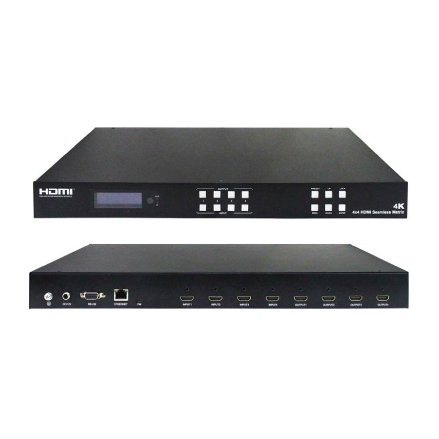
- Page 1 4x4 Seamless Switch 4K HDMI Matrix & Video Wall Controller...
- Page 2 Operating Instruction Thank you for purchasing this product. For optimum performance and safety, please read these instructions carefully before connecting, operating or adjusting this product. Please keep this manual for future reference. SAFETY PRECAUTIONS Please read all instructions before attempting to unpack, install or operate this equipment and before connecting the power supply.
-
Page 3: Table Of Contents
Operating Instruction CONTENTS 1. DEAR CUSTOMER·······················································4 2. FEATURES··································································4 3. NOTICE······································································4 4. SPECIFICATIONS························································ 5 5. PACKAGE CONTENTS················································· 5 6. OPERATION CONTROLS AND FUNCTIONS····················6 6.1 Front Panel ··········································································· 6 6.2 Rear Panel············································································· 6 6.3 Remote Control Description························································ 7 7. CONNECTING AND OPERATING···································7 8. -
Page 4: Dear Customer
Operating Instruction 1. Dear Customer Thank you for purchasing this product. For optimum performance and safety, please read these instructions carefully before connecting, operating or adjusting this product. Please keep this manual for future reference. The Matrix offers solutions for digital entertainment center, HDTV retail and show site, HDTV, STB, DVD and projector factory, noise, space and security concerns, data center control, information distribution, conference room presentation, school and corporate training environments. -
Page 5: Specifications
Operating Instruction 4. SPECIFACATIONS Operating Temperature Range 0 to +40°C (32 to +104°F) Operating Humidity Range 5 to 90 % RH (no condensation) Input Video Signal 0.5-1.0 volts p-p Input DDC Signal 5 volts p-p (TTL) DTV/HDTV: 1080P/1080i/720P/ Video Format Supported 576P/480P/4K Audio Format Supported LPCM 2.0... -
Page 6: Operation Controls And Functions
Operating Instruction 6. OPERATION CONTROLS AND FUNCTIONS 6.1 Front Panel ① LCD screen and IR receiving port, indicator light ② Input button IN1~4: choose the desired input port from ports 1~4 Output button OUT1~4: choose the desired output port from ports 1~4 ③... -
Page 7: Remote Control Description
Operating Instruction 6. 3 Remote Control Description Power on/off Mute button previous source and next source Enter the seamless matrix mode(red) Enter the video wall mode(green) Enter the multi-viewer mode(blue) Enter the mirror viewer mode(yellow) MENU button: to enter the main menu interface or return to the previous menu interface All button: choose all Output port. -
Page 8: Panel Control
Operating Instruction 8. Panel control 8.1 Video switch operation Signal switching includes 4 switching channels, which can be randomly configured as input/output according to requirements to form a matrix of 1×4~4×1. It can switch any input signal to 1 channel of output or all channels of output. -
Page 9: Video
Operating Instruction 8.2.1 Video 1). Video switch Operation: In the main menu, select "Video" to press the "OK". press “ up and down” button to select "Output1" (The fifth ALL option means that all outputs are selected) click on "OK" to enter the next submenu Press the“... - Page 10 Operating Instruction Press the “up and down” button to select the "On/Off" Click "OK" to enter the next submenu Press “up and down” button to select Off or On. Press the "OK" button to confirm that the output port is open/ closed. 3).
- Page 11 Operating Instruction You can choose any one of the output video resolution, or choose all of the output video resolution, the system default use Auto (this option is the product according to the displays judgment). 4). OffSet Operation: In the video wall mode, select the "Video" in the main menu to press the "OK"button. Press the “up and down”...
- Page 12 Operating Instruction You can select the offset(The margin of the display screen) of any one of the output video, or select the offset for all of the output video screens. (Offset apply to video wall mode). 5). Rotate Operation: In the main menu, select "Video" to press the "OK" Press “...
- Page 13 Operating Instruction You can choose any output(such as output1)’s color Settings or select all output the picture color Settings, you can set the contrast, brightness, saturation, color, and R, G, B offset, etc.You also can choose the “Reset” to restore all the default Settings.Each option can be set 0-100 (the system default parameters for 50), the color of the above parameters can be set according to your own preferences.
- Page 14 Operating Instruction Click "OK" to enter the next submenu. Press the “up and down” button to select the "CH0" to close or the "CH1" is open Click the "OK" button to complete the setting. You can choose the area (one of the output port’s) to display CH0 or CH1. 8).
- Page 15 Operating Instruction You can choose one of CH0 output video screen size and the size of the cutting video screen, or select all CH0 output video screen size and the size of cutting all output video image, the size of the coordinates of the out displays in the upper left corner and the lower right corner, full screen coordinates (0, 0, 6000600), adjust the picture size and cut size need to set the starting point and end point.
- Page 16 Operating Instruction Corp: Zoom: 9). CH1 CH1 has one more select Source function. Crop and Zoom are the same as the operation steps of CH0 main channel. You can select one of the CH1 output video screen size and the size of the cutting video screen, or select the size of all CH1 output video screen and the size of the all output cutting video screen.
- Page 17 Operating Instruction When we click "Next", then the signal source of CH1 is the next signal source, and the output screen is the image of the next signal source. When we click "Mute", then close the CH1 image,.After we select “Mute” ,the CH1 screen is black screen.
-
Page 18: Mode
Operating Instruction Vertical mirror diagram Horizontal mirror diagram 8.2.2 Mode The Mode control interface has 4 submenus: 1). Seamless matrix Mode Seamless is the interface of Seamless switch of matrix, Seamless can seamlessly switch all input signal sources, can choose 1~4 signal sources, or choose P2P (one signal source to one screen) Operation: In the main menu, select "Mode"... - Page 19 Operating Instruction 2). Video-wall Mode Video-wall can select 4 display sets to make a picture.There are 10 preset scenes (2x2, 1x2x2, 1x2, 2x1x2, 2x1, 2x1 1x2, 1x3, 3x1, 1x4, 4x1). After clicking, you can select the scene you need. Operation: In the main menu, select "Video-wall"...
- Page 20 Operating Instruction 2x1x2 1x2x2...
- Page 21 Operating Instruction 2x1 1x2...
- Page 22 Operating Instruction * That's the Video wall preview. Each black frame represents a TV and each different picture represents different input source. The same picture in multiple television means that the same input source is allocated to multiple TVS to make up the video wall. 3).
- Page 23 Operating Instruction 4). Mutli-viewer mode Mutli-viewer can select a preset segmentation scene. The image segmentation can only one output way, not multiple output to segmentation. Operation: In the main menu, select "Mutli-viewer" to press the "OK". Press the “up and down” button to select the "Output" Click the "OK"...
- Page 24 Operating Instruction 2x3 L 2x3 U...
-
Page 25: Audio Settings Interface
Operating Instruction * That’s mutli-viewer preview. The black frame represents a TV ( the output1-4 you selected). The picture shows four input sources.If you choose a source to set the mutli-viewer , the other three screens will also change according to the input1-4, until you select the output screen. 5). - Page 26 Operating Instruction...
-
Page 27: Edid Settings
Operating Instruction 8.2.4 EDID Settings EDID setting interface can set EDID of each input port, and you can choose one mode of built-in EDID, which has two resolutions: 2160P and 1080P. Operation: In the main menu, select "EDID" to press the "OK". Press “... -
Page 28: Setup Interface
Operating Instruction 1). Save Settings If there is no save scenario, the factory default P2P mode will be invoked. Operation : Click the "Preset" button on panel. Press the “up and down” button to select the "Save". Click "OK" to enter the next submenu. Press the”... - Page 29 Operating Instruction 2). DHCP switch The DHCP interface "On" is set as dynamic and "Off" is set as static.If the system restates factory ,the default DHCP as Off. Operation: In the main menu, select "Setup" to press the "OK" . Press the”...
- Page 30 Operating Instruction 4). Factory setting It is an initialization setting for the device function. There are two factory settings: 1. Factory-Run 2. Factory-User Factory-Run is the recovery operation data. The factory-User can restore the factory settings for all settings. Operation: In the main menu, select "Setup"...
-
Page 31: Query Information Interface
Operating Instruction 8.2.7 Query information interface Inquiry device information, such as IP information, system information, each device different MAC , default IP is 192.168.1.168 and 255.255.255.0. -
Page 32: Connection Diagram
Operating Instruction 9. CONNECTION DIAGRAM Application 1: Seamless Switch 4x4 HDMI Matrix Application 2: Diagram of Video Wall Displaying... -
Page 33: Ip Control
Operating Instruction 10. IP Control 10.1 IP setting 1). The default mode is “Static IP Address”,you just connect the matrix to your computer over the Ethernet cable 2). You can also select "Use the following IP Address",click "OK" button to set IP address (Make sure the IP address in the same range with your PC) Note: You need get an IP address from the Router or set Static IP Address first. -
Page 34: Switch Setting
Operating Instruction 10.2 Switch setting The Video interface is divided into: 1). Seamless matrix mode 2). Video wall mode 3). Mutli-viewer mode The current state can be set through the Onekey2x2 butto In the Video interface, one-to-one and one-to-many Video switching can be realized. One-to-one Video switching: first click any Output in Video Output, then select signal Source in the Source button and click the corresponding signal Source (Input1~Input4) to complete the switching operation. -
Page 35: Format
Operating Instruction 10.3 Format Select Video Output that needs to be changed in Video Output, and the selected block will turn blue. Click on the Format button to change Output resolution (it support single select, multiple select or all select), and click on the resolution to set it successfully. 10.4 Video Offset 1). -
Page 36: Modify Port Name
Operating Instruction Scene save For example, input signal 1 to all output ports, then save it to Preset1, Operation: Select the All button in the Output region and the 01 button in the Input region. Select Preset 1 in the Store region; Then select “Save”... -
Page 37: Audio
Operating Instruction 10.7 Audio Audio interface can only control the output Audio and display the current Audio status in real time. Mute; Speaker; Delay second setting Audio operation: output1/2/3/4 corresponds to each Output,Output All corresponds to All Output, the operation is consistent; Audio: click the corresponding output to close the output Audio or start Audio;... -
Page 38: Network Interface Description
Operating Instruction EDID operation: select the Input port first. And then select 4K or 1080P to switch. is displayed in the Input key to indicate the information of the first Input port EDID, followed by 01 to indicate the Input port.This button indicates that the default EDID1 is copied to input... -
Page 39: System Interface Description
Operating Instruction 12. System interface description 1. “user name” represents changing the user name 2. “new password” indicates the new password to enter the login interface 3. “Confirm the password” indicates that the new password is entered again. After the input is complete, click apply to complete the modification. -
Page 40: The Firmware Update
Operating Instruction 13.The firmware update 13.1.MCU application layer upgrade Open the software UART_ISP.exe at the PC, select the correct port, the baud rate 115200, input the "A1" in port, and select the path (.bin format) of the program, and click “update”... -
Page 41: Gui Application Layer Upgrade
Operating Instruction 13.3 GUI Application layer upgrade Open the software UART_ISP.exe at the PC and select the correct port, baud rate 115200, enter A1 _01 (_ for spaces) in port. Then select the program (.bin format) in path, and click “update” to complete the upgrade. -
Page 42: Maintenance
Operating Instruction MAINTENANCE Clean this unit with a soft, dry cloth. Never use alcohol, paint thinner of benzine to clean this unit. PRODUCT SERVICE (1) Damage requiring service: The unit should be serviced by qualified service personnel if: (a) The DC power supply cord or AC adaptor has been damaged; (b) Objects or liquids have gotten into the unit;... - Page 43 Operating Instruction LIMITED WARRANTY LIMITS AND EXCLUSIONS 1). This Limited Warranty ONLY COVERS failures due to defects in materials or workmanship, and DOES NOT COVER normal wear and tear or cosmetic damage. The Limited Warranty ALSO DOES NOT COVER damages which occurred in shipment, or failures which are caused by products not supplied by warrantor, or failures which result from accidents, misuse, abuse, neglect, mishandling, misapplication, alteration, faulty installation, set-up adjustments, misadjustment of consumer controls, improper maintenance, power line surge, lightning...
Need help?
Do you have a question about the BL-4X4S-VW22 and is the answer not in the manual?
Questions and answers