Advertisement
Quick Links
TRACTOR & LOADER GENERAL INFORMATION
Mounting kit can be installed using tools ordinarily
available, including a hoist capable of lifting and sup-
porting the loader for initial mounting, standard
wrenches and a torque wrench, hydraulic oil, and a
non-sparking drift and hammer (a shot-filled mallet is
recommended).
Tractor-supplied hydraulic power is required for loader
mounting and operation. Two hydraulic kits options are
available for use with this loader:
A hose kit for use with existing tractor hydraulic
control valves, which includes hoses and couplings
to plumb to tractor rear remote valve couplers.
This mounting kit is compatible with KIOTI model
MM20-60 mid-mounted mower. Also compatible with
RHINO or SMC model 65A backhoe.
If optional grille guard is to be installed, install it during
mid mounting bracket installation, before mounting
loader. Refer to instructions provided with grille guard.
Check tractor tire pressure. Refer to tractor operator's
manual for recommended pressures. With tractor on a
firm, level surface, compare tractor rear axle height from
left to right, measuring from axle center to ground.
Adjust air pressure in rear tires until axle height mea-
sures same for both sides.
NOTE: If rear axle on tractor is not level from side to
side, cutting edge on loader bucket or similar loader-
mounted attachments will not sit flat on ground.
When loader mounting is complete, you will need to
check front tire clearances and adjust tire track width as
necessary. You will also need to verify tractor wheel and
axle clearances and adjust steering stops accordingly to
provide clearance between front tire and tractor hood
and loader on full left and right turn with front axle fully
oscillated. Be sure lift cylinders are fully retracted when
checking tire clearances. Refer to tractor operator's
manual for steering stop adjustment.
F-3984
ASSEMBLY MANUAL
Keep With Operator's Manual
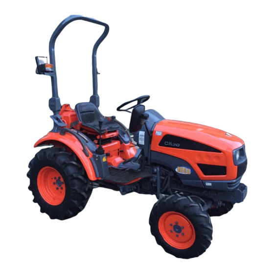
2406TL LOADER MOUNTING KIT
KIOTI TRACTORS
MODEL
2WD
CK20
CK20HST
Page 1 of 6
FWA
X
X
PREPARING TRACTOR
Shut off engine, engage brakes, and remove key during
installation. If tractor is equipped with front weights,
remove weights. It is not necessary to remove weight
bracket.
Remove plastic thread protectors from holes on left and
right sides of tractor.
INSTALLING LEFT & RIGHT MIDMOUNTING
BRACKETS
NOTE: Install all attaching hardware loose until
mounting kit is completely assembled, to facilitate
assembly and proper alignment-unless noted
otherwise. Torque all hardware to torques specified
in General Torque Specifications table when
assembly is complete.
NOTE: Support mid mounting brackets (1 & 2)
when removing from shipping materials.
1.
Raise left midmounting bracket (1) with overhead
hoist. Align mounting holes with holes in casting on
left side of tractor. Attach mounting and spacers (3)
to clutch housing casting using 14MM x 55MM cap
screws (4) and 9/16" lock washers (6). Attach to
front frame using 12MM x 35MM cap screws (5)
1/2" flat washers (8) and 1/2" lock washers.(7)
2.
Raise right midmounting bracket (2) with overhead
hoist. Allign mounting holes with holes in casting on
right side of tractor. Attach mounting and spacer (3)
to clutch housing casting using 14MM x 55MM cap
screws (4) and 9/16" lock washers (6). Attach to
front casting using 12MM x 35MM cap screws (5)
1/2" flat washer (8) and 20MM lock washers (7).
3.
Tighten 14MM hardware to 85 ft. lbs. (115 N•M) and
12MM hardware to 52 ft. lbs. (70 N•M) of torque.
2-7439
4-04-06
Advertisement

Subscribe to Our Youtube Channel
Summary of Contents for Kioti CK20
- Page 1 Torque all hardware to torques specified This mounting kit is compatible with KIOTI model in General Torque Specifications table when MM20-60 mid-mounted mower. Also compatible with assembly is complete.
- Page 2 2-7439 Figure 1 PARTS LIST – MOUNTING KIT Item Part No. Description Qty. 52444-1 MOUNTING BRACKET, Mid, Left 52444-2 MOUNTING BRACKET, Mid, Right 52105 PLATE, Support 42672-22 SCREW, Cap, 14MM-1.50MM x 55MM 42672-24 SCREW, Cap, 12MM-1.25MM x 35MM 41837-6 WASHER, Lock, 9/16 41837-5 WASHER, Lock, 1/2 42502-10...
- Page 3 2-7439 MOUNTING LOADER TO TRACTOR (Figures 2, 3, 4, Lower loader from vertical shipping position to 5, 6, 7 & 8) horizontal, positioning scraps of cardboard on floor under loader to protect loader paint (see figure 2B). WARNING: Loader must be supported before removing hardware securing loader Install hydraulic plumbing for loader to tractor using to shipping pallet, or loader will tip over.
- Page 4 2-7439 Figure 4 Figure 6 13. Attach tilt cylinder function hoses (color coded blue With overhead hoist, position loader upright pin to clear mount pin saddle by 1” (see figure 5). Start and red) to corresponding tractor valve couplers. tractor engine and move tractor forward until both loader upright pins come to rest against flat vertical 14.
- Page 5 2-7439 INSTALLING BUCKET OR ATTACHMENT To adjust level indicator properly, locate tractor and loader attachment on a firm level surface with attach- Refer to loader operator's manual to install bucket or ment resting on level surface in operating position. optional attachments. Loosen U-bolt that fastens level indicator bracket to right tilt cylinder and position it so it is centered on the offset WARNING: Always have a bucket...
- Page 6 2-7439 GENERAL TORQUE SPECIFICATIONS USE THE FOLLOWING TORQUES WHEN SPECIAL TORQUES ARE NOT GIVEN Standard American and Metric Cap Screws AMERICAN STANDARD CAP SCREWS METRIC CAP SCREWS SAE Grade Metric Class 10.9 Typ. Head Typ. Head Markings Markings Cap Screw TORQUE TORQUE Cap Screw...


Need help?
Do you have a question about the CK20 and is the answer not in the manual?
Questions and answers
Çok 20 ye kaç no motor yağı konur
The suitable engine oil for the Kioti CK20 is 15W-40 Kioti Oil.
This answer is automatically generated