Table of Contents
Advertisement
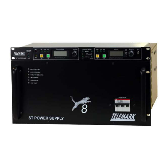
ST SERIES ELECTRON BEAM
POWER SUPPLY
INSTRUCTION MANUAL
Copyright © TELEMARK, 1995-2020 – All rights reserved
Manual Rev 1.0.0 June 2020
telemark.com
Download the current version of this manual at
https://telemark.com/e-beam-power-supplies/solid-state/
Brand and product names are trademarks or registered trademarks of their respective companies
Advertisement
Table of Contents

Related Manuals for Telemark ST Series

Summary of Contents for Telemark ST Series
- Page 1 ST SERIES ELECTRON BEAM POWER SUPPLY INSTRUCTION MANUAL Copyright © TELEMARK, 1995-2020 – All rights reserved Manual Rev 1.0.0 June 2020 telemark.com Download the current version of this manual at https://telemark.com/e-beam-power-supplies/solid-state/ Brand and product names are trademarks or registered trademarks of their respective companies...
-
Page 2: Table Of Contents
ST Series Power Supply Instruction Manual TABLE OF CONTENTS 1 INTRODUCTION ................7 INTENDED PURPOSE .................7 USER RESPONSIBILITY ..............7 SYSTEM DESCRIPTION ..............8 1.3.1 The High Voltage Power Supply ................8 1.3.2 The Filament Output Transformer ................8 1.3.3 The ST Controller ....................8 1.3.4... - Page 3 ST Series Power Supply Instruction Manual INTERFACES ..................22 2.7.1 Interlocks (Required) .................... 22 2.7.2 Remote I/O (Optional) ..................22 3 INSTALLATION ................. 23 UNPACKING ..................23 3.1.1 Component Lists ....................24 RACK INSTALLATION ................ 26 GROUNDING ..................27 CONNECTING THE ST POWER SUPPLY ......... 29 3.4.1...
- Page 4 ST Series Power Supply Instruction Manual STORAGE AND DISPOSAL ............... 54 6.2.1 Packaging ......................54 6.2.2 Storage ......................... 54 6.2.3 Disposal ....................... 54 6.2.4 WEEE ........................54 7 TROUBLESHOOTING ............... 55 BASIC TROUBLESHOOTING ............55 7.1.1 HV Overvoltage Fault ................... 55 7.1.2...
- Page 5 ST Series Power Supply Instruction Manual TABLE OF FIGURES Figure 1-1, Keep Foreign Material Out of the ST Power Supply ..........11 Figure 1-2, Examples of High Voltage warning labels ...............14 Figure 2-1, ST Power Supply Part Numbers ................15 Figure 2-2, ST HVPS Reference Dimensions ................16 Figure 2-3, ST Filament Transformer Dimensions ..............17...
- Page 6 ST Series Power Supply Instruction Manual Figure 5-2, Remote I/O Pinout, Bottom Row ................50 Figure 6-1, WEEE Symbol ......................54 Figure 9-1, Connections ST series 400VAC Version ..............61 Figure 9-2, Connections ST series 208VAC Version ..............62 Figure 9-3, J4 Remote User I/O Connector ................63 Figure 9-4, J4 Remote User I/O Connector ................64...
-
Page 7: Introduction
(See chapter 2.3 and Figure 2-6, ST Electrical Specifications for more info.) The Telemark ST High Voltage Electron Beam Power Supply will be referred to as the ST Power Supply for the remainder of this manual. -
Page 8: System Description
If the user has a reasonable doubt about understanding the use or installation of a component, Telemark Service should be contacted. It is vitally important that the user properly install the equipment as described in Chapter 3 (Installation) of this manual. -
Page 9: Liabilities And Warranty
ST Controller installed in the instrument rack. 1.4 LIABILITIES AND WARRANTY Telemark is not liable for damages resulting from improper use of the device and any guarantees expire, if the user, or a third party: •... - Page 10 INTRODUCTION ST Series Power Supply Instruction Manual DANGER Information on preventing any kind of physical injury. Information on preventing extensive equipment and WARNING environmental damage. CAUTION Information on correct handling or use. Disregarding safety notes can lead to malfunctions or equipment damage.
-
Page 11: General Safety Concerns
INTRODUCTION ST Series Power Supply Instruction Manual 1.5.4 General Safety Concerns Pay attention to the following safety notes: Foreign Objects: DANGER Contact with electrically energized parts is extremely hazardous when any objects are introduced, or any liquids penetrate the device. -
Page 12: High Voltage Safety
DO NOT allow anyone who has not reviewed this manual to perform any part of the installation process or attempt servicing of the power supply. Any questions must be brought to the attention of Telemark's service personnel. DO NOT obstruct the cooling inlets or outlets. Overheating can result, which may damage the power supply. - Page 13 INTRODUCTION ST Series Power Supply Instruction Manual Use decals or other warning labels on the High Voltage shield, at the front of the E-beam chamber DANGER and on the door(s) to the room(s) housing the chamber and power supply to provide a warning that lethal voltages are present.
-
Page 14: Figure 1-2, Examples Of High Voltage Warning Labels
INTRODUCTION ST Series Power Supply Instruction Manual Examples of High Voltage warning labels include, but are not limited to: Figure 1-2, Examples of High Voltage warning labels 14 of 64 telemark.com Rev 1.0.0... -
Page 15: Specifications
SPECIFICATIONS ST Series Power Supply Instruction Manual 2 SPECIFICATIONS 2.1 ST POWER SUPPLY MODELS Part Number Description Output HV and Emission ranges 107-9941-1 ST-4 Power Supply, Cheetah, 208V HV: 0 to -8kV; Emission: 0 to 500mA 107-9944-1 ST-4 Power Supply, Cheetah, 400V HV: 0 to -8kV;... -
Page 16: Mechanical Specifications
SPECIFICATIONS ST Series Power Supply Instruction Manual 2.2 MECHANICAL SPECIFICATIONS 2.2.1 The High Voltage Power Supply The High Voltage Power Supply (See Figure 2-2) occupies a standard 5U-19” rack compartment. Physical dimensions are: 8.73” (222mm) Height: 19.00” (483mm) Width: 23.58” (599mm) Overall, 22.07” (561mm) from rack face Length: Net Weight: 56 lb. -
Page 17: The St Filament Output Transformer
SPECIFICATIONS ST Series Power Supply Instruction Manual 2.2.2 The ST Filament Output Transformer The ST Filament Transformer (See Figure 2-3) is placed at a point between the Power Supply and the HV feedthroughs. It is usually placed or mounted below the deposition chamber with the interconnecting cables routed to the High Voltage Power Supply in the instrument rack. -
Page 18: The St Controller
SPECIFICATIONS ST Series Power Supply Instruction Manual 2.2.3 The ST Controller The ST Controller (See Figure 2-4) provides external controls for the operation of the ST Power Supply. It occupies a standard 1U 19” rack compartment. Physical dimensions are: 1.72” (43.7mm) Height: 19.00”... -
Page 19: The Handheld (Optional)
SPECIFICATIONS ST Series Power Supply Instruction Manual 2.2.4 The Handheld (Optional) The Handheld controller offers more freedom of movement while controlling the ST Power Supply output. Comes with 15ft interconnect cable. Physical dimensions are: 1.94” (49.3mm) Height: 3.49” (88.7mm) Width: 5.9”... -
Page 20: Electrical Specifications
0 to 40A Figure 2-6, ST Electrical Specifications * All ST Power Supplies are also available with optional 50A maximum filament current supplies – please contact Telemark if 50A output current is required Specifications subject to change without notice NOTE: The above specified line currents are average maximum currents at full load and at lowest specified line voltage. -
Page 21: Environmental
SPECIFICATIONS ST Series Power Supply Instruction Manual 2.4 ENVIRONMENTAL The ST Power Supply -20…+60 °C Temperature Storage: +5…+40 °C Operation Temperature: Relative Humidity: Max. 80 % (up to 31 °C), decreasing to max. 50 % (above 40 °C) Use indoor only Altitude: max. -
Page 22: Interfaces
SPECIFICATIONS ST Series Power Supply Instruction Manual 2.7 INTERFACES The ST Power Supply interfaces to the Process Chamber controls via two D- Subminiature interface connections. One is required for interlock status and safety, and one is optional for Remote Process Control. -
Page 23: Installation
INSTALLATION ST Series Power Supply Instruction Manual 3 INSTALLATION 3.1 UNPACKING 1. Before unpacking, visually inspect the transport packaging for signs of external damage. 2. Unpack the ST Power Supply components and place the packaging material aside. NOTE: Keep the packaging material for future use! The ST Power Supply must be stored and transported in the original packaging material only. -
Page 24: Component Lists
INSTALLATION ST Series Power Supply Instruction Manual 3.1.1 Component Lists The following is a comprehensive list of the components included with the ST Power Supply System. Part # Description Photo (See Figure High Voltage Power Supply (HVPS) 3-2) 105-0012-5 Filament Output Transformer Box... -
Page 25: Figure 3-3, Cable Kit Components
INSTALLATION ST Series Power Supply Instruction Manual 122-5104-1, Cable Kit Components Part # Description Photo 122-0610-1 15pin D-Sub, Control Cable, M-F, 10 feet 122-0706-2 25pin D-Sub, Control Cable, F-F, 10 feet 122-0706-3 25pin D-Sub, Control Cable, M-M, 10 feet 122-3103-2-15... -
Page 26: Rack Installation
INSTALLATION ST Series Power Supply Instruction Manual 3.2 RACK INSTALLATION The ST Power Supply is designed to be mounted in a standard 19-inch electronic instrument rack. Any suitable place on a vacuum system that has a standard 19-inch- wide opening may be used. -
Page 27: Grounding
INSTALLATION ST Series Power Supply Instruction Manual 3.3 GROUNDING Proper grounding is the single most important aspect of the installation of the E- beam. During arcing events, RF noise is generated that must be properly driven to ground to avoid interference/damage. For this reason, the E-beam ground must be separate from the electronics rack ground and ideally as short as possible. -
Page 28: Figure 3-4, Suggested Grounding Connections
INSTALLATION ST Series Power Supply Instruction Manual Rack Deposition 14 AWG Controller (2.5mm ) Sweep Indexer Power Supply CHAMBER Controller GROUND 6 AWG (16mm ) Power Supply Filament Transformer 14 AWG (2.5mm ) CHAMBER RETURN 6 AWG is for distances up to 10 feet (3 meters) -
Page 29: Connecting The St Power Supply
INSTALLATION ST Series Power Supply Instruction Manual There are also 4 ground connections to be maintained between the rack-installed instruments and the HVPS but not directly to chamber ground: 1. ST-Controller - connected using 14 AWG gauge (2.5mm ) wire. -
Page 30: Figure 3-5, Interconnections For The St Power Supply
INSTALLATION ST Series Power Supply Instruction Manual Figure 3-5, Interconnections for the ST Power Supply 30 of 64 telemark.com Rev 1.0.0... -
Page 31: Hvps Connections
INSTALLATION ST Series Power Supply Instruction Manual 3.4.1 HVPS Connections Figure 3-6, HVPS Rear Panel Connections A - J1 HV CONTROL >>> connects to J1 of Controller B - J2 INTERFACE I/O >>> connects to J2 of Controller C - J3 SOURCE CONTROL >>>... -
Page 32: Filament Output Transformer Connections
INSTALLATION ST Series Power Supply Instruction Manual 3.4.2 Filament Output Transformer Connections Figure 3-7, Filament Output Transformer Connections to HVPS A – J4 HV INPUT >>> connects to J4 of HVPS B – J7 FILAMENT INPUT >>> connects to J7 of HVPS C –... -
Page 33: System Interconnection
INSTALLATION ST Series Power Supply Instruction Manual 3.4.4 SYSTEM INTERCONNECTION Turn OFF all front and rear panel circuit breakers. Connect the bottom ground stud on the rear panel of the HVPS chassis to a common ground on the vacuum system. See Figure 3-4 for Grounding information, wire gauges, and connections. -
Page 34: Mains Connection
INSTALLATION ST Series Power Supply Instruction Manual When all connections have been double checked, remove any lockout/tag outs, and apply AC power from the AC line input. Turn both rear panel circuit breakers ON. The unit is now ready for operation. -
Page 35: Interlock I/O
INSTALLATION ST Series Power Supply Instruction Manual Pin# Name Description AC Phase 1 AC Ground / Physical Earth AC Neutral, (400V models only.) AC Phase 2 AC Phase 3 Figure 3-9, MAIN POWER, Line Input 1. Connect the power connector to the mains cable. -
Page 36: St Controller Interlock I/O
INSTALLATION ST Series Power Supply Instruction Manual 3.5.2 ST Controller Interlock I/O J6 – INTERLOCKS – External Safety Interlocks (15pin Sub-D M) Pin # Name Function Description Power VAC Interlock Return Return for pin 2 VAC Interlock Contact closure to pin 1... -
Page 37: Standard Operation
STANDARD OPERATION ST Series Power Supply Instruction Manual 4 STANDARD OPERATION This chapter covers the standard operation of the ST Power Supply. It will familiarize the user with the basic functions and indicators of the HVPS and the ST Controller and instruct the user in the best operating practices. -
Page 38: Figure 4-2, Hvps Rear Panel Functions
STANDARD OPERATION ST Series Power Supply Instruction Manual 6 – STEP START fault indicator 7 – MAIN CIRCUIT BREAKER Turns the unit on and off. Prevents excessive input current. Figure 4-2, HVPS Rear Panel Functions 8 – AUX CONTROL BREAKER Prevents excessive current for Control Power generation. -
Page 39: St Controller Functions And Indicators
STANDARD OPERATION ST Series Power Supply Instruction Manual 4.2 ST CONTROLLER FUNCTIONS AND INDICATORS The ST Controller front panel includes a power on indicator and is divided into 3 functional areas: Local High Voltage Control, Control Input Selection, and Local Source Control Figure 4-3, Controller Front Panel 1. -
Page 40: High Voltage Functions
STANDARD OPERATION ST Series Power Supply Instruction Manual 4.2.1 High Voltage Functions Figure 4-4, High Voltage Control Functions Name Type Function FAULT Indicator Red LED Lit when HVPS Fault is present. (check HVPS front panel indicators) VAC Interlock Indicator Green LED Lit when VAC interlock is satisfied. -
Page 41: Control Select Functions
STANDARD OPERATION ST Series Power Supply Instruction Manual 4.2.2 Control Select Functions Figure 4-5, Control Select Functions Name Type Function Control Indicator – HV Remote Green LED Lit when HV is being controlled via Remote. Control Indicator – HV Handheld Green LED Lit when HV is being controlled via Handheld. -
Page 42: Source Functions
STANDARD OPERATION ST Series Power Supply Instruction Manual 4.2.3 Source Functions Figure 4-6, Source Control Functions Name Type Function HVAC Interlock Indicator Green LED Lit when HVAC interlock is satisfied. H20 Interlock Indicator Green LED Lit when H20 interlock is satisfied. -
Page 43: Operation
STANDARD OPERATION ST Series Power Supply Instruction Manual 4.3 OPERATION Here we will discuss the proper Initial Start-up and Standard Operation procedures for the ST Power Supply. 4.3.1 Initial Start-Up When all connections have been made as described in Chapter 3 – INSTALLATION, the power supply is ready for use. -
Page 44: Standard Operation
Wait for about 15 to 30 seconds (to allow for filament preheating). NOTE: A good range for setting the bias for Telemark sources is between 17 to 21A, settings for other sources need to be determined by trial and error (yellow glow of the filament, but still a few amps below emission point) but should be very similar. -
Page 45: Handheld Operation
STANDARD OPERATION ST Series Power Supply Instruction Manual This procedure will extend the filament lifetime, allow for more precise control in the low emission current range, and prevent initial rate spikes from emission current overshoot on evaporation materials requiring very low power levels. (Such as subliming materials.) - Page 46 STANDARD OPERATION ST Series Power Supply Instruction Manual 46 of 64 telemark.com Rev 1.0.0...
-
Page 47: Remote Operation
REMOTE OPERATION ST Series Power Supply Instruction Manual 5 REMOTE OPERATION Remote Operation (from Process Controller or PLC) Switching the Control Select toggle to the Remote position hands over all controls and voltage setpoints for HV and Emission to connector J4 (Remote I/O) on the rear panel of the ST Controller. -
Page 48: Remote User I/O Pinouts
REMOTE OPERATION ST Series Power Supply Instruction Manual NOTE: For safety reasons the OFF pushbuttons, both HV and Source, are always enabled regardless of the Control mode selection. J4 also provides several status and analog signal feedbacks to the Process Controller for complete process control. See Chapter 9: Figure 9-3, J4 Remote User I/O Connector and Figure 9-4, J4 Remote User I/O Connector for more details. -
Page 49: Figure 5-1, Remote I/O Pinout, Top Row
REMOTE OPERATION ST Series Power Supply Instruction Manual Top Row Pins Pin# Name In, Out, Signal Range Function Description Power User +24VDC Power +24VDC Source for user +24VDC control (200mA max output) HV Ready/OFF Output 0 to +VCC Low = HV ready/off Indicator (O.C.)*... -
Page 50: Figure 5-2, Remote I/O Pinout, Bottom Row
REMOTE OPERATION ST Series Power Supply Instruction Manual Bottom Row Pins Name Input/ Signal Range Function Description Output/ Power Not Connected Unused Not Connected Unused Not Connected Unused Not Connected Unused All Interlocks OK Output 0 to +VCC Low = All Interlocks satisfied Indicator (O.C.) *... - Page 51 REMOTE OPERATION ST Series Power Supply Instruction Manual Note 3: When using "User +24VDC" for inductive loads (e.g. relays) on pins 2-6, 24 and 26, then "User +24VDC" must be connected to "+VCC" (pin 1 to pin 31). In the case of incorrect connection in accordance with...
- Page 52 REMOTE OPERATION ST Series Power Supply Instruction Manual 52 of 64 telemark.com Rev 1.0.0...
-
Page 53: Maintenance And Storage
• Check and confirm all electrical wires, connections and contactors in the main power supply cabinet are clean and showing no sign of overheating or other damage. If there are signs of overheating, contact Telemark Service and Support. Check all mechanical connections and terminal block connections, to assure they are clean, and connections are tight. -
Page 54: Storage And Disposal
6.2.1 Packaging Please keep the original packaging. The packaging is required for storing the ST Power Supply and for shipping it to a Telemark service center if required. 6.2.2 Storage The ST Power Supply may only be stored in a dry room. The following requirements must be met: -20….+60 °C... -
Page 55: Troubleshooting
TROUBLESHOOTING ST Series Power Supply Instruction Manual 7 TROUBLESHOOTING 7.1 BASIC TROUBLESHOOTING Whenever the ST Power Supply enters a latched fault condition, one of the several fault condition LEDs on the front panel of the HVPS, as well as the red Fault LED on the ST Controller, will light up. -
Page 56: Hv Out Of Regulation
TROUBLESHOOTING ST Series Power Supply Instruction Manual Possible causes for this fault include: Emitter assembly malfunction inside the vacuum chamber resulting in a heavy arc condition or emitter short. Process material may have found its way between the Emitter assembly and the crucible source, or in between the High Voltage feedthrough and grounded cover. -
Page 57: Rail Current Fault
TROUBLESHOOTING ST Series Power Supply Instruction Manual An Arc Counter Fault will occur when there are too many continuous arcing events detected within a specified amount of time as set by the factory. Possible causes for this fault include: Process arcing inside the chamber. -
Page 58: Contacting Service
TROUBLESHOOTING ST Series Power Supply Instruction Manual 7.2 CONTACTING SERVICE If service or repair is required for your unit, please contact Telemark Service and Support. We can be reached via the following: Phone: +1 (360)723-5360 E-Mail: sales@telemark.com Contact information is at https://telemark.com/contact/... -
Page 59: Warranty Conditions
This warranty shall not apply if repair has been performed or an alteration made by anyone other than an authorized Telemark representative or if a malfunction occurs through abuse, misuse, negligence, or accident. No charge will be made for repairs made under warranty at Telemark’s facilities. -
Page 60: Addendum
ADDENDUM ST Series Power Supply Instruction Manual 9 ADDENDUM • Figure 9-1 Connections ST-4/6/8/10, 400VAC • Figure 9-2 Connections ST-4/6/8/10, 208VAC • Figure 9-3 J4 Remote User I/O Connector • Figure 9-4 J4 Typical Remote User I/O Connections 60 of 64 telemark.com... -
Page 61: Figure 9-1, Connections St Series 400Vac Version
ADDENDUM ST Series Power Supply Instruction Manual Figure 9-1, Connections ST series 400VAC Version 61 of 64 telemark.com Rev 1.0.0... -
Page 62: Figure 9-2, Connections St Series 208Vac Version
ADDENDUM ST Series Power Supply Instruction Manual Figure 9-2, Connections ST series 208VAC Version 62 of 64 telemark.com Rev 1.0.0... -
Page 63: Figure 9-3, J4 Remote User I/O Connector
ADDENDUM ST Series Power Supply Instruction Manual Figure 9-3, J4 Remote User I/O Connector 63 of 64 telemark.com Rev 1.0.0... -
Page 64: Figure 9-4, J4 Remote User I/O Connector
ADDENDUM ST Series Power Supply Instruction Manual Figure 9-4, J4 Remote User I/O Connector 64 of 64 telemark.com Rev 1.0.0...
Need help?
Do you have a question about the ST Series and is the answer not in the manual?
Questions and answers