Advertisement
Quick Links
Advertisement

Related Manuals for Palram ORANGERY


Summary of Contents for Palram ORANGERY
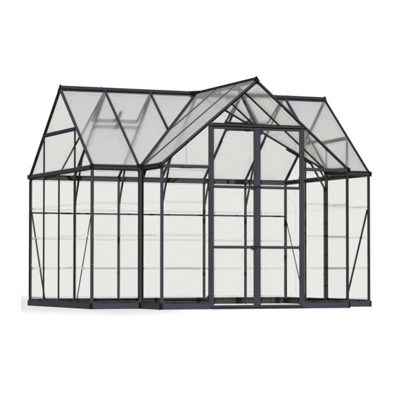
- Page 1 ORANGERY 18-02-2010 - MA...
- Page 2 Index SECTION PAGE NO. Foreword Safety Tips User notes Assembly Tips Method of Assembly Exploded view Base Construction Components List Profiles and fittings - component identification Method of assembly STAGES OF ASSEMBLY: Stage 1 Side Frame assembly Stage 2 Assembly of front gable Stage 3 Assembly of rear gable Stage 4...
-
Page 3: Safety Tips
Foreword Your aluminium greenhouse is designed to give you many years of trouble -free service. By carefully following the steps contained in this manual, you will have a greenhouse of which to be proud. Your aluminium greenhouse must be built upon a firm, level surface. For those greenhouse's without an integral base, the optional galvanised steel base is an ideal foundation but you may also prepare a base from bricks, concrete blocks or impregnated timber. - Page 4 Method of Assembly First install base as per instructions Check base is square and level Begin construction of greenhouse side section Construct Door Gable Construct the 2 rear gables Assembly side section to Rear Gables Fit main Ridge Bar Fit Roof Glazing Bars ( and Vent Trimmers) Construct 1,2m sides Fix Door Gable to 1.2m sides Fit Ridge Bar to Door Gable and main Ridge...
-
Page 5: Exploded View
Exploded view Side frame Vent Rear gable Roof Door gable Side frame Side frame Door Rear gable... - Page 6 Orangery Base Construction 1) Ensure greenhouse base is sited on a firm, flat surface. 2) Lay-out base components as shown. 3) Connect long side 3170mm to rear base 1908mm at both ends by fitting ground anchors to matching holes in base sections.
-
Page 7: Components List
Components List Pos Description Length [mm] Qty Pos Description Length [mm] Qty 01 Side glazing bars 1341 27 Vent trimmer 02 Gutter 3110 28 Door stile 1815 Gutter 1273 29 Door rail top Gutter 30 Door rail centre 03 Base sill side 3110 31 Door rail bottom Base sill... - Page 8 Profiles and fittings - component identification...
- Page 9 Method of assembly Please read through these instructions carefully before you assemble the greenhouse. Each kit contains a components list. Layout the components and check all items against this list before you begin assembly. Having established that the components are complete, familiarise yourself with each section by reference to the Identification Chart on previous page, and to the labels on individual aluminium components.
- Page 10 Assembly of front gable Stage 2 Identify and layout the components in the configuration shown in the diagram. Slide door seal into left (17) and right (16) hand door posts. Locate right-handed corner post (5) onto front base sill (18) and secure with bolt and nut through pre-punched holes in bothcomponents.
- Page 11 Assembly of front gable...
- Page 12 Assembly of rear gable Stage 3 Identify and layout the components in the configuration shown in the diagram. Locate right-handed corner post (5) onto base sill (6) and secure with bolt and nut through pre-drilled holes in BOTH components. Now slide a square headed bolt into the channel at the back of the right hand intermediate glazing bar (7) and loosely secure together with diagonal brace (8) to base sill (6).
- Page 13 Assembly of rear gable...
- Page 14 Assembly of gable ends to side Stage 4 Bolt endgable to side section through pre-punched holes. It will be found helpful to slide two bolts into each gable bar and corner post and to hold these in position by securing with finger-tight nuts BEFORE offering the sections into position. Add second rear gable.
- Page 15 Joining of ridge bar(s) Stage 5 Connect ridge bar fixing bracket to ridge with nut and bolt through pre-drilled hole. Rest machined end of ridge bar onto original and locate opposite end so that the flanges are underneath the gable. Release finger tight nut on remaining bolts in gable and slide nut and bolt assembly into locating slots in ridge bar.
- Page 16 Fitting of Roof Slope and Brackets...
- Page 17 Assembly of the vent Stage 9 The vent assembly is made up of a head (24), two sides (25), a vent sill (26) and is glazed with a sheet of glass 610mm x 610mm. Place two bolts through the pre-punched holes in the vent head, slide both vent sides (25) over the bolt heads and secure with nuts.
- Page 18 Glazing Stage 11 Choose a day when the weather conditions are calm and you have sufficient time to complete the glazing in one operation. 1. IMPORTANT NOTICE: The roof and eaves bracing (40) must be fitted and fully secured before glazing is commenced.
- Page 19 Multi - pane Glazing Side Roof Rear gable Rear gable Side Side Roof Side Side Front gable...
- Page 20 Full lenght toughened glass Side Roof Rear gable Rear gable Side Side Roof Side Side Front gable...
- Page 21 End stops Position plastic rainwater outlets and stop ends into ends of eaves bars. NOTE: The two rainwater outlets contained in this package are sealed across the outlet. Simply knock out the membrane at the end of the outlet with a piece of dowel or similar instrument to provide a drop-end.
-
Page 22: Door Assembly
Door assembly Stage 12 Layout the door components. Loosely bolt the rails to the stiles (28) as shown. The top rail (29) should fit closely to the top of the stiles and the bottom rail (31) should protrude below the stiles. Fit glazing strip (42) to stiles, and by adjusting position of rails, glaze the door with two pieces of 610mm x 610mm glass and one piece of 61 Omm x 320mm.
Need help?
Do you have a question about the ORANGERY and is the answer not in the manual?
Questions and answers