Advertisement
Quick Links
I
NSTRUCTION
DC P
OWERED
M
M
ODEL
S
ERIAL
V
ESTIL
2999 N
ORTH
T
: (260) 665-7586 -
ELEPHONE
U
:
.
RL
WWW
VESTILMFG
H
YDRAULIC
CART-DS-1000 (DC)
ODEL
N
. ________________________
O
N
. ________________________
O
M
ANUFACTURING
W
S
, P.O. B
AYNE
TREET
F
: (260) 665-1339
AX
.
COM
M
ANUAL
E
LEVATING
C
507, A
OX
NGOLA
- T
F
(800) 348-0868
OR
OLL
REE
E
:
MAIL
SALES
C
ART
.
ORP
, IN 46703
@
.
VESTIL
COM
Advertisement

Related Manuals for Vestil CART-DS-1000


Summary of Contents for Vestil CART-DS-1000
- Page 1 NSTRUCTION ANUAL DC P OWERED YDRAULIC LEVATING CART-DS-1000 (DC) ODEL . ________________________ ODEL . ________________________ ERIAL ESTIL ANUFACTURING 2999 N , P.O. B 507, A , IN 46703 ORTH AYNE TREET NGOLA : (260) 665-7586 - (800) 348-0868 ELEPHONE : (260) 665-1339...
- Page 2 Vestil is not liable for any injury or property damage that occurs as a consequence of failing to apply the safe operation and maintenance procedures explained in this manual or that appear on labels affixed to the product.
- Page 3 ABLE OF ONTENTS Safety Principles Product Introduction Safety Guidelines Parts List Use Instructions 10-13 Loading Lift Table Operation Battery Charger 11-12 Hydraulic System Operation 12-13 Maintenance & Inspections Troubleshooting ABLE OF IGURES FIG. 1: Labeled Photograph FIG. 2A: DC Modular Power Unit Electrical Components FIG.
- Page 4 Cart operators should have access to the manual at all times and should review the directions before each use. Contact Vestil for answers to any question you have after reading the entire manual.
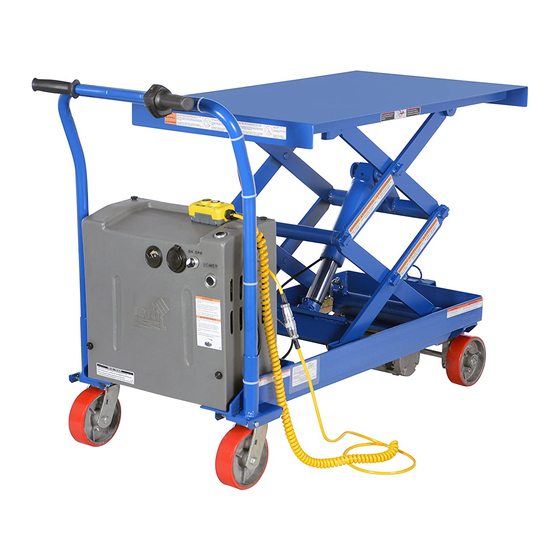
- Page 5 FIG. 1: Labeled Photograph 7; 9; 10 5; 7; 9 6; 8; 9 Modular Power Unit (MPU) diagram and parts lists on p. 6-7 Item Contact Vestil to order Part No. Description Quantity replacement or spare parts 01-210-005 Leg weldment assembly (see cover page).
- Page 6 FIG. 2A: DC Modular Power Unit (MPU) Electrical Components - 6 -...
- Page 7 DC Modular Power Unit Hydraulic Components FIG. 2B: - 7 -...
- Page 8 FIG. 3: E -- M LECTRICAL IAGRAM ODULAR OWER To reduce the possibility of injury, BEFORE working on the electrical system: 1. Fully lower and secure the deck; 2. Remove all system pressure and power sources; 3. DO NOT work on the electrical components UNLESS you are trained and authorized to do so.
- Page 9 FIG. 4: H – L YDRAULIC IAGRAM OWER CIRCUITS reduce the possibility injury, BEFORE working hydraulic system: 1. Fully lower and secure the deck; 2. Remove system pressure disconnect power sources; 3. DO NOT work on hydraulic components UNLESS you are trained authorized to do DO NOT use...
-
Page 10: Use Instructions
NSTRUCTIONS The cart is suitable for use in most industrial and commercial settings. Only authorized persons should use the scissors lift cart. “Authorized person” means someone the end-user approves or assigns to use the cart because he/she is either: 1. Qualified: Someone with demonstrated ability to deal with problems relating to the scissors lift cart by virtue of having a recognized degree, certificate, or professional standing, and who additionally has knowledge of, training related to, and experience with scissor lifts carts;... - Page 11 ABLE PERATION Instruct other persons in the area to stand at a safe distance while the deck raises or lowers. Be certain no part of any person, clothing, or object is under any part of the platform before lowering the deck. The Modular Power Unit (MPU) controls the scissors lift table portion of the cart by means of a constant pressure (dead-man style) pushbutton controller.
- Page 12 Remember to unplug the charger before moving the equipment to prevent damaging the cords, receptacles, and other equipment. Operating the battery with a low battery voltage might cause premature motor contact failure. YDRAULIC SYSTEM PERATION An electric motor directly coupled to a gear-type hydraulic pump produces the fluid pressure and flow the cylinder requires to raise the deck and a load.
-
Page 13: Maintenance And Inspections
• Pull the bottom of the cylinder out of the push assembly and raise the end up higher than any other part of the hydraulic system. Rotate the cylinder so the hose port is pointing up. • Loosen the hose fitting by a ½ turn; then “jog” the motor. Oil and air will sputter from the loose fitting. Once the air is gone, tighten the fitting and replace the cylinder into the push assembly. - Page 14 ROUBLESHOOTING If the unit does not operate, check all of the electrical connections. In particular, examine the connections at the battery, the motor, and all points at which a wire connects to the chassis. Also check the quick-connect plug at the end of the pendant control cord.
- Page 15 ARKINGS Only use the lifter if ALL labels are readable and undamaged. Contact Vestil for replacement labels if necessary, and DO NOT use the lifter until all replacement labels are affixed to the device. FIG. 6: Label placement Label #207:...
Need help?
Do you have a question about the CART-DS-1000 and is the answer not in the manual?
Questions and answers