Table of Contents
Advertisement
Quick Links
OPERATING AND MAINTENANCE INSTRUCTIONS MANUAL
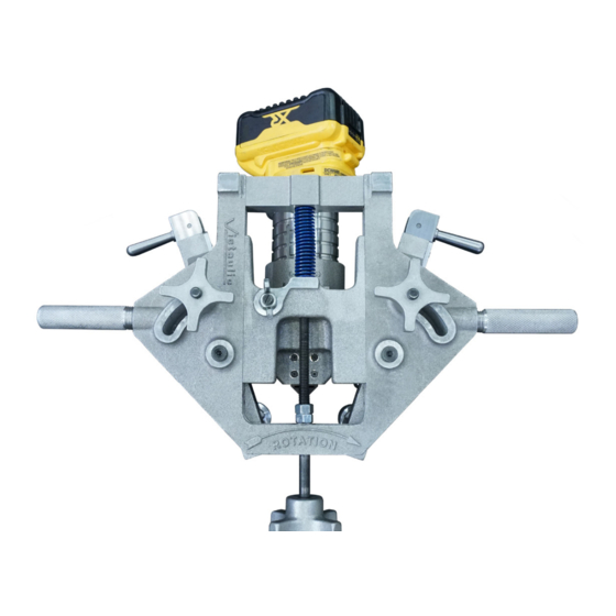
CPVC/PVC Cut Grooving Tool
WARNING
If you need additional copies of any literature, or if you have questions concerning the safe
and proper operation of this tool, contact Victaulic, P.O. Box 31, Easton, PA 18044-0031,
Phone: 1-800-PICK VIC, E-Mail: pickvic@victaulic.com.
REV_C
WARNING
Failure to follow instructions and warnings could result in death,
serious personal injury, property damage, and/or product damage.
• Before operating or servicing any grooving tools, read all
instructions in this manual and all warning labels on the tool.
• Wear safety glasses, hardhat, foot protection, and hearing
protection while working around this tool.
• Save this operating and maintenance manual in a place
accessible to all operators of the tool.
Original Instructions
TM-CG1100
TM-CG1100
Advertisement
Table of Contents

Related Manuals for Victaulic CG1100

Summary of Contents for Victaulic CG1100
- Page 1 If you need additional copies of any literature, or if you have questions concerning the safe and proper operation of this tool, contact Victaulic, P.O. Box 31, Easton, PA 18044-0031, Phone: 1-800-PICK VIC, E-Mail: pickvic@victaulic.com.
-
Page 3: Table Of Contents
TM-CG1100 / Operating and Maintenance Instructions Manual TABLE OF CONTENTS Hazard Identification ....4 Operator Safety Instructions ... . 4 Introduction . -
Page 4: Hazard Identification
TM-CG1100 / Operating and Maintenance Instructions Manual HAZARD IDENTIFICATION OPERATOR SAFETY INSTRUCTIONS Definitions for identifying the various hazard levels are provided below . The CG1100 CPVC/PVC Cut Grooving Tool is designed for the sole purpose of cut grooving This safety alert symbol indicates CPVC and PVC pipe . - Page 5 TM-CG1100 / Operating and Maintenance Instructions Manual DANGER CAUTION Avoid using the tool in dangerous Inspect the equipment. Before using the environments. Do not use the tool on tool, check all moveable parts for any sloped or uneven surfaces . Do not use the obstructions .
-
Page 6: Introduction
Victaulic Company. The Victaulic CG1100 CPVC/PVC Cut Grooving Tool is a portable tool for cut grooving CPVC and PVC pipe to to be compatible with Victaulic grooved piping products . The standard CG1100 tool is equipped to groove 2–12 inch/DN50- Qty. -
Page 7: Power Requirements
1b. Insert the battery into the battery charger . 1c. When a battery is inserted into the The CG1100 tool connects directly to a 20V battery charger, the red indicator light will Max, 6 .0 Ah lithium ion battery pack for blink on and off . -
Page 8: Tool Nomenclature
TM-CG1100 / Operating and Maintenance Instructions Manual TOOL NOMENCLATURE NOTICE • Drawings and/or pictures in this manual may be exaggerated for clarity. • The tool, along with this operating and maintenance instructions manual, contains trademarks, copyrights, and/or patented features that are the exclusive property of Victaulic. -
Page 9: Tool Dimensions And Specifications
TM-CG1100 / Operating and Maintenance Instructions Manual TOOL DIMENSIONS AND SPECIFICATIONS 17.27 in/ 438.7 mm 18.11 in/ 460.0 mm 7.51 in/ 190.7 mm Tool weight is 20 .7 pounds/9 .4 kilograms when using 2–4 inch arms, and 21 .9 pounds/ 9 .9 kilograms when using 6–12 inch arms . -
Page 10: Pipe Setup
28–30 of this serious personal injury. manual . Select a location for the grooving operation by The CG1100 tool is intended for field or shop taking into consideration the following factors set up . (refer to “Tool Dimensions And Specifications”... -
Page 11: Setup For 2 4 Inch Pipe
TM-CG1100 / Operating and Maintenance Instructions Manual SETUP FOR 2 – 4 INCH PIPE 2–4 Inch Arm Set Up 1. Unscrew and remove the arm locking knobs . 4. The 2–4 inch arms must be mounted on the tool in a specific orientation . Match the “A” or “B”... -
Page 12: Inch "A" Dimension Set Up
TM-CG1100 / Operating and Maintenance Instructions Manual 2–4 Inch “A” Dimension Set Up 6. Replace the arm locking knobs and screw down until the arms are secure against the body 1. Loosen the wing nut on the “A” adjustment of the tool . -
Page 13: Inch Cutter Bit Setup
. Retain the packaging for future storage . 2–4 Inch Cutter Bit Setup WARNING • The bits shipped with the CG1100 tool have a custom radius for grooving. Do not substitute off-the-shelf square bits. Always use bits provided by Victaulic. - Page 14 TM-CG1100 / Operating and Maintenance Instructions Manual 3. While pressing the spindle lock button, use 5. While pressing the spindle lock button, use the 11/16-inch wrench to loosen the collet . Remove the 11/16-inch wrench to tighten the collet . Do not the 6–12 inch bit .
- Page 15 TM-CG1100 / Operating and Maintenance Instructions Manual NOTICE • Ensure that it is the TIP of the bit that is meeting the line on the alignment block, rather than a radiused corner or other edge of the bit. Visually confirm the accuracy of this adjustment from all angles.
-
Page 16: Setup For 6 12 Inch Pipe
TM-CG1100 / Operating and Maintenance Instructions Manual SETUP FOR 6 – 12 INCH PIPE 6–12 Inch Arm Set Up 9c. Verify the alignment of the tip of the cutter bit with the appropriate line on the alignment block . The cutter bit pictured above is set for 2 .5 to 4-inch pipe . - Page 17 TM-CG1100 / Operating and Maintenance Instructions Manual 7. Tighten the shoulder bolts using the provided 4. The 6–12 inch arms are interchangeable hex key . and may be mounted on the tool in either orientation . Insert the arms into the body of the tool .
-
Page 18: Inch "A" Dimension Set Up
TM-CG1100 / Operating and Maintenance Instructions Manual 6–12 Inch “A” Dimension Set Up 4. Tighten the wing nut on the “A” adjustment screw, located on the front of the tool . 1. Loosen the wing nut on the “A” adjustment screw, located on the front of the tool . - Page 19 2a. Retrieve the 6–12 inch cutter bit from its packaging . Retain the packaging for future storage . WARNING • The bits shipped with the CG1100 tool have a custom radius for grooving. Do not substitute off-the-shelf square bits. Always use bits provided by Victaulic.
- Page 20 TM-CG1100 / Operating and Maintenance Instructions Manual 7. Use the provided 5/64-inch T-handle hex key to loosen the set screw . This will allow the depth stop to move . 5. While pressing the spindle lock button, use the 11/16-inch wrench to tighten the collet . Do not overtighten .
- Page 21 TM-CG1100 / Operating and Maintenance Instructions Manual 9a. Select the appropriate cutter bit location by 9c. Verify the alignment of the tip of the cutter matching the pipe size to the corresponding line bit with the appropriate line on the alignment on the alignment block .
-
Page 22: Tool Mounting
TM-CG1100 / Operating and Maintenance Instructions Manual TOOL MOUNTING DANGER • DO NOT connect the battery until instructed otherwise. Failure to follow this instruction could result in serious personal injury. 1. If grooving for the first time, or if grooving a different diameter or wall thickness pipe 3. - Page 23 TM-CG1100 / Operating and Maintenance Instructions Manual CAUTION • Do NOT leave the tool unsupported by the operator while mounted on pipe. Failure to follow this instruction could result in tool damage or personal injury. DISENGAGED ENGAGED 7a. Push the tool through one complete clockwise rotation to check for obstructions and to allow the tool to track onto the pipe .
-
Page 24: Grooving Operation
TM-CG1100 / Operating and Maintenance Instructions Manual GROOVING OPERATION 1. Mount the tool as directed in the “Tool Mounting” section . WARNING • Ensure that the motor switch is turned OFF before connecting the battery to the tool. Failure to follow this instruction could result in personal injury. - Page 25 . NOTICE • When grooving additional pipe ends with the same specifications, mount the CG1100 tool onto the pipe and engage the handles without resetting the tool. • After tool set-up is complete, reset is only necessary when changing pipe specifications.
-
Page 26: Maintenance
TM-CG1100 / Operating and Maintenance Instructions Manual 12e . Once adjustment is complete, continue to hold the 3/16-inch hex key in position, and tighten the set screw using the 5/64-inch hex key . 12f. Perform another trial groove to verify that the correction has brought the “C”... -
Page 27: Troubleshooting
Adjust groove bit position. Foreign material caught between depth stop Clean depth stop and rollers to remove foreign material. and pipe. In the event of tool malfunction outside the scope of the troubleshooting section, contact Victaulic for assistance. REV_C TM-CG1100_27... -
Page 28: Pgs-300 Groove Dimensions For Cpvc And Pvc Products
TM-CG1100 / Operating and Maintenance Instructions Manual PGS-300 GROOVE DIMENSIONS FOR CPVC AND PVC PRODUCTS WARNING • Pipe dimensions and groove dimensions must be within the tolerances specified in the tables on the following pages to verify proper joint performance. - Page 29 “T” Dimension – The “T” dimension is the lightest grade (minimum nominal wall thickness) of pipe that is suitable for grooving . NOTICE • Coatings that are applied to the interior surfaces of Victaulic grooved and plain-end pipe couplings must not exceed 0.010 inch/0.25 mm. This includes the bolt pad mating surfaces.
-
Page 30: Cut Groove Specifications
TM-CG1100 / Operating and Maintenance Instructions Manual REV_C TM-CG1100_30... - Page 31 TM-CG1100 / Operating and Maintenance Instructions Manual This page intentionally blank REV_C TM-CG1100_31...
- Page 32 TM-CG1100 OPERATING AND MAINTENANCE INSTRUCTIONS MANUAL CPVC/PVC Cut Grooving Tool UPDATED 04/2020 TM-CG1100 10373 REV C VICTAULIC IS A REGISTERED TRADEMARK OF VICTAULIC COMPANY IN THE UNITED STATES AND/OR OTHER COUNTRIES. © 2020 VICTAULIC COMPANY. ALL RIGHTS RESERVED.
Need help?
Do you have a question about the CG1100 and is the answer not in the manual?
Questions and answers