Table of Contents
Advertisement
Advertisement
Table of Contents

Subscribe to Our Youtube Channel
Related Manuals for Weaver W10-HD

Summary of Contents for Weaver W10-HD
- Page 2 W10-HD Installation & Operation Manual 10,000 lb. Capacity Overhead Asymmetric Two Post Lift Derek Weaver Company, Inc. 2950 SE Loop 820 Fort Worth, TX 76140 817-560-9510 www.derekweaver.com...
-
Page 3: Table Of Contents
CONTENTS Product Features and Specifications ..........1 Installation Requirement .............4 Steps of Installation ……………………………………………………………………………….6 Exploded View ................25 Test Run ...................33 Operation Instruction ..............35 Maintenance ................35 Trouble Shooting ...............36 Lift disposal ..................37... -
Page 4: Product Features And Specifications
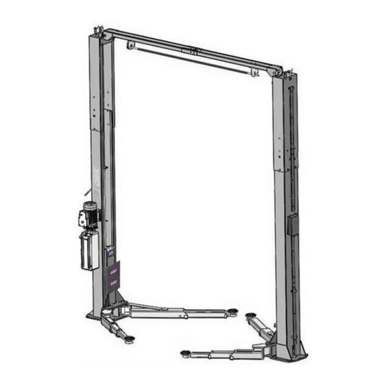
I. PRODUCT FEATURES AND SPECIFICATIONS CLEAR-FLOOR DIRECT-DRIVED MODEL FEATURES Model W10-HD (See Fig. 1) · Direct-drived design, minimize the lift spare parts and breakdown ratio · Dual hydraulic cylinders, designed and made as ANSI standards, utilizing imported oil seal in cylinder ·... - Page 5 Arm Swings View Fig 2 Attention! Please make sure to place the arms in correct position before car drive in! Car in Fig 3...
-
Page 6: Installation Requirement
II. INSTALLATION REQUIREMENT A. TOOLS REQUIRED Rotary Hammer Drill (Φ19) Carpenter’s Chalk Hammer Screw Sets Level Bar Tape Measure (7.5m) English Spanner (12") Pliers Ratchet Spanner with Socket (28 Socket Head Wrench (3 ... - Page 7 B. Equipment storage and installation requirements. The equipment should be stored or installed in a shady, normal temperature, ventilated and dry place. C. The equipment should be unload and transfer by forklift. Fig.5 D. SPECIFICATIONS OF CONCRETE (See Fig. 6) Specifications of concrete must be adhered to the specification as following.
-
Page 8: Steps Of Installation
III. STEPS OF INSTALLATION A. Location of Installation Check and insure the installation location (concrete, layout, space size etc.) is suitable for lift installation. B. Use a carpenter’s chalk line to establish installation layout of base-plate (See Fig.7). Click a line 135”... - Page 9 3. Loose the screws of the upper package stand, take off the upper extension columns, take out the parts in the inner column and remove the package stand. 4. Move aside the parts and check the parts according to the shipment parts list. (See Fig.10, 11).
- Page 10 W10-HD: Not suitable for installation when the height of the workshop is less than 143-4 / 4 "; only low setting installation for height between 143-5 / 4" -151-5 / 8 ";...
- Page 11 1. High setting installation, choose the low holes of the outer column and install with the inner column. High setting Fig.15 2. Low setting installation, choose the high position holes of the outer column and install with the inner column. (See Fig.16). Low setting Fig.16...
- Page 12 F. Position columns (See Fig. 17) Position the columns on the installation layout of base-plate, Install the anchor bolts. Check the Columns plumpness with level bar, and adjusting with the shims if the columns are not vertical. Do not tighten the Anchor Bolts. Width between Columns: 112-1/4”...
- Page 13 G. Install overhead top beam 1. The hook on the top coupling assembly is hung on the outer column to lock the screws, and then the top beam is installed (See Fig. 18) Fig. 18...
- Page 14 2. Install the top beam, fixed the anchor bolts Tighten the anchor bolts with ratchet spanner with socket Note: Torque of Anchors is 150N.m Fig.19...
- Page 15 H. Installing the limit switch control bar and limit switch (See Fig. 20). Loosen screw of drive rod for adjustment, tighten the screw after adjustment Adjust drive rod of limit switch Limit switch connected with cable Connect the blue wire to terminal 11# on limit switch and terminal A1 on AC contactor of power unit...
- Page 16 I. Install safety device (See Fig. 20 & Fig. 21). Powerside safety device Fig.21 77B 77C Offside safety device Fig.22...
- Page 17 J. Lift the carriages up and make them be locked at the same level (See Fig. 23). Fig. 23...
- Page 18 K. Install cables 1. Low setting cable connection (See Fig. 23). Low Setting installation holes Cable2 Cable1 Cable2 Fig. 24...
- Page 19 2.High setting cable connection 2.1. Cable pass through from the bottom of the carriages and be pulled out from the open of carriages, then screw the two cable nuts (See Fig. 25). High Setting installation holes Screw the two cable nuts Cable Connecting direction Cable connecting direction Fig.
- Page 20 2.2 Connecting cable for high setting (See Fig. 26). Cable 2 Cable 1 Cable 2 Fig. 26...
- Page 21 L. Install oil hose. (See Fig. 27). Fig.27...
- Page 22 M.Install protective cover. (Fig.28) Install M6*35 Screw 1、 Put on M6*40 Screw; 2、 Install protective cover, tighten the screws Only high setting Install protective cover and fix the oil hose Fig.28...
- Page 23 N. Install safety cable (See Fig. 29) Wire cable Wire cable across pulley bracket Install wire from Offside safety device first Wire cable connect to powerside safety device Fig.29...
- Page 24 O. Install Protective Covers Note: Requirement of installation for oil hose and safety device. 1. Install Oil Hose. Note: Don’t cross the oil hose and safety cable together (See Fig. 30 & Fig. 31). Tie the hose cable with a tape Safety Cable Oil Hose Wire Cable...
- Page 25 P. Install lifting arms and adjust the arm locks 1. Install the lifting arms (See Fig. 35). 2. Lowing the carriages down to the lowest position, then use the socket head wrench to loosen the socket bolt (See Fig. 36). Loosen the Bolt Use the 8 Socket Head Wrench...
- Page 26 4. Adjust moon gear and arm lock to make it to be meshed, then tighten the socket bolts of arm lock (See Fig. 38). Q. Tighten all the hydraulic fittings, and fill the reservoir with hydraulic oil. Note: In consideration of Hydraulic Power Unit’s durability and keep the equipment running in the perfect condition, please use Hydraulic Oil 46#.
-
Page 27: Exploded View
IV. EXPLODED VIEW Fig. 40... - Page 28 PARTS LIST FOR W10-HD Item Part# Description W10-HD NOTE 10206019 Snap Ring 10209012 Elastic latch 10209128 Washer φ20 10209057B Bronze Bush for Pulley 11206020 Pulley 11279023 Power-side Inner Column 10209003 Hex Bolt 10209004 Rubber Ring 10209005 Self-locking Nut 11217436 Safety device spacer...
- Page 29 10217044 Arm Lock 206032 Snap Ring φ25 10206036 Hair Pin φ6*40 10209016 Carriage Plastic Cover 11206046B Arm Lock Bar (right) 11217168 Arm pin assy. 10520023 Snap Ring 10206190 Tool tray 11206191 Toe guard bar 10209019 Screw 10209018 Protective Rubber 11279004 Carriage Front right Arm 10279010...
- Page 30 1061K074 Wire guard 11203752 Wire protective cover 10206110 Cup head bolt 11206084 Protective Cover(L=200mm) 11206083 Protective Cover(L=385mm) 11217004 Active safety control block 11217029 Safety Pulley Bracket 10217008 Torsion spring 11217031 Driven safety control block 10217032 Wire cable connecting pin 10217033 Tension nut 10203778 Protective Cover...
- Page 31 4.1 Rear arm assy. (10279011) explosive view Fig.41 Part no Name Part no Name Hex nut Rear outer arm 10206048 11206192 washer Cup head bolt 10209039 10201149 washer Rear inner arm 10209022 11206193 Moon gear 11206049 4.2 Left front arm assy. (10279009) explosive view Fig.42 Part no Name...
- Page 32 4.3 Right front arm assy. (10279010) explosive view Fig.43 Part no Name Part no Name Hex nut Front left outer arm 10206048 11206182 washer Front middle arm 10209039 11206189 washer Cup head bolt 10209022 10201149 Moon gear Front inner arm 11206049 11201049A 4.4 Cylinder (11217056) explosive view...
- Page 33 Part list for cylinder Part no Name Part no Name 30-1 10209069 O-ring 30-8 11217076 Piston rod Piston Rod 30-2 10209070 Bleeding Plug 30-9 11209077 Fitting 30-3 10209071 Support Ring 30-10 10209078 Dust wing 30-4 10209072 Y-ring 30-11 11209079 cover 30-5 10209073 O-ring...
- Page 34 Part list of power unit (220V/60HZ/single phase) Part no Name Part no Name Rubber pad AC contractor 81400180 81400287 81400130 Starting capacitor 71111104 Motor wiring cover Running capacitor Throttle valve 81400088 81400560 Screw with washer Relief valve 10420148 81400266 Capacitor cover Plug 81400066 81400284...
-
Page 35: Test Run
Release valve Oil return port Relief valve Oil output port Release valve handle throttle valve Check valve Fig 46 V. TEST RUN 1. Adjust synchronous cable (See Fig. 47) Use wrench to hold the cable fitting, meanwhile use ratchet spanner to tighten the cable nut. Make sure two cables are with the same tension Adjust so that two carriages can work synchronously. - Page 36 4. Adjust the lower speed You can adjust the lower speed of the lift if needing: Turn the Throttle Valve in clockwise direction to decrease the lower speed, or increase the speed in counterclockwise direction. Throttle valve Throttle valve Clockwise to decrease the Counterclockwise to decrease down speed the down speed...
-
Page 37: Operation Instruction
VI. OPERATION INSTRUCTIONS Please read the safety tips carefully before operating the lift To lift vehicle 1. Keep clean of site near the lift; 2. Position lift arms to the lowest position; 3. To shortest lift arms; 4. Open lift arms; 5. -
Page 38: Trouble Shooting
Note: All anchor bolts should take full torque. If any of the bolts does not function for any reason, DO NOT use the lift until the bolt has been replaced. Every six months: 1. Make a visual inspection of all moving parts for possible wear, interference or damage. -
Page 39: Lift Disposal
1. Safety device are in activated 1. Release the safeties 2. Release Valve in damage 2. Repair or replace Lift cannot lower 3. Safety cable broken 3. Replace 4. Oil system is jammed 4. Clean the oil system IX. Lift disposal When the car lift cannot meet the requirements for normal use and needs to be disposed, it should follow local laws and regulations.
Need help?
Do you have a question about the W10-HD and is the answer not in the manual?
Questions and answers