Table of Contents
Advertisement
Quick Links
Advertisement
Table of Contents

Related Manuals for Sunell Hi3536C Series

Summary of Contents for Sunell Hi3536C Series
- Page 1 Network Video Recorder (NVR) User Manual Issue V4.3 Date 2019-10-21...
-
Page 2: Legal Notice
Network Video Recorder User Manual Legal Notice Legal Notice Trademark Statement: VGA is trademark of IBM Corporation. The Windows logo and Windows are trademarks or registered trademarks of Microsoft Corporation. Other trademarks or company names that may be mentioned in this document are the property of their respective owners. - Page 3 Network Video Recorder Legal Notice User Manual official website. If the paper and electronic files are inconsistent, please refer to the electronic file as. The company reserves the right to modify any information in this document at any time. ...
-
Page 4: Network Security Advice
Network Video Recorder User Manual Network Security Advice Network Security Advice Required measures to ensure basic network security of equipment: Modify the factory default password and use a strong password Devices that do not change the factory default password or use a weak password are the easiest to be hacked. - Page 5 Network Video Recorder Network Security Advice User Manual Forward only the network ports that must be used. Avoid forwarding a long port area. Do not set the device's IP to DMZ. If the camera is connected locally to the NVR, you do not need to forward the port for each camera.
- Page 6 Network Video Recorder User Manual Network Security Advice If you want to know if your device is secure, you can check the logs to find some unusual access operations. The device log will tell you which IP address you have tried to log in or what the user has done.
-
Page 7: About This Document
Network Video Recorder About This Document User Manual About This Document Purpose This document describes in detail the installation, use, and interface operations of the NVR (Network Video Recorder) device. Model Series model Hi3536C SN-NVR2504E1-P4、SN-NVR2508E1-P8、SN-NVR2508E2-P8、SN- NVR2516E2-P16、SN-NVR2504E1、SN-NVR2508E1、SN- NVR2516E2、SN-NVR2532E2 Hi3536 SN-NVR2632E4-P16、SN-NVR2632E4、SN-NVR2664E4、SN- NVR2632E8、SN-NVR2664E8、SN-NVR2604E1-P4、SN-NVR2608E1- P8、SN-NVR2604E1-P4-J、SN-NVR2608E1-P8-J Hi3536D SN-NVR2404E1-E(II)、SN-NVR2408E1-E(II)、SN-NVR2404E1-E、SN-... - Page 8 Network Video Recorder User Manual About This Document channel setting Increase the allocation of permissions by channel V 4.2 Add boot wizard Add toolbar Add manual recording and timely playback Add multiple clicks to enlarge Add user lockout Remove the upper right corner to display the alarm warning Add the view of the latest alarm information, modify the manual alarm...
- Page 9 Network Video Recorder About This Document User Manual synchronization interval. Add access to thermal imaging cameras and display IPC product models Remove auto hide Add the patrol route and line sweep function Add upgrade IPC, restart IPC, restore factory Increase the selection of primary and sub stream backups Add click playback button to play video Add UI display granular IPC intelligence...
-
Page 10: Symbol Conventions
Network Video Recorder User Manual About This Document Add 1+7 split screen Add channel information display Add 3D ball machine Remove the video type switch from the scene Add RAID Add S.M.A.R.T Add formatting (fat32 and NTFS) Support event video quick download backup Add event video backup Add the full screen of the bomb and send the screenshot... -
Page 11: Safety Instructions
Network Video Recorder Safety instructions User Manual Safety instructions The following are the correct use of the product. In order to prevent danger and prevent property damage, please read this manual carefully before using the device and strictly comply that when using it. -
Page 12: Important Statement
Network Video Recorder User Manual Safety instructions Use a power supply that meets the SELV (Safety Extra Low Voltage) requirements and supply power according to the rated voltage of IEC60950-1 in accordance with the Limited Power Source. The specific power supply requirements are based on the equipment label. ... -
Page 13: Table Of Contents
Network Video Recorder Contents User Manual Contents Legal Notice ......................... ii Network Security Advice ..................iv About This Document .................... vii Purpose ..........................vii Model ..........................vii Modify Log ........................vii Symbol Conventions ......................x Safety instructions ..................... xi Requirements ........................xi Power Requirement ...................... - Page 14 Network Video Recorder User Manual Contents 2.2 Back Panel ........................7 2.3 Important Notes ......................14 2.4 About This User Manual ....................15 2.5 Installation Environment and Precautions ..............15 3 Install device ......................17 3.1 Process ......................... 17 3.2 Unpacking Inspection ....................18 3.3 Install Hard Disk ......................
- Page 15 Network Video Recorder Contents User Manual 6.5.1 Face Comparison ....................66 6.5.2 Face Search ...................... 67 6.5.3 Face Library ..................... 68 6.5.4 Comparison Configuration ................69 6.6 Attendance........................71 6.6.1 Attendance Data ....................71 6.6.2 Attendance Management .................. 72 7 UI System Setting ....................76 7.1 Channel Information.....................
- Page 16 Network Video Recorder User Manual Contents 7.6 Network Management ....................100 7.6.1 Network......................100 7.6.1.1 IP ......................101 7.6.1.2 Port......................101 7.6.1.3 POE ......................102 7.6.1.4 WiFi Parameter ..................103 7.6.1.5 WiFi Network ..................104 7.6.2 802.1 X ......................105 7.6.3 DDNS ......................
- Page 17 Network Video Recorder Contents User Manual 7.7.8 Maintenance ....................130 7.7.9 Auto Restart ....................131 8 WEB Quick Start ....................133 8.1 Activation ........................133 8.2 Login and Logout ....................... 134 8.3 Browsing Videos ......................139 8.3.1 Browsing Real-Time Videos ................139 8.3.2 Live Video ......................
- Page 18 Network Video Recorder User Manual Contents 9.2 Record ........................170 9.2.1 Record Schedule .................... 170 9.2.2 Disk ........................ 172 9.2.3 RAID ......................172 9.2.4 S.M.A.R.T ...................... 174 9.3 Alarm ......................... 175 9.3.1 General ......................175 9.3.2 Motion Detection ................... 176 9.3.3 Video Loss......................
- Page 19 Network Video Recorder Contents User Manual 9.6 Local........................... 203 10 Disk Compatibility .................... 204 Issue: V4.3(2019-10-21)
-
Page 21: Preface
Network Video Recorder Preface User Manual 1 Preface 1.1 Product Description This product is a high performance NVR device. The product has local preview, video multi- screen split display, local real-time storage function of video files, support for mouse shortcut operation, remote management and control functions. -
Page 22: Playback
Network Video Recorder User Manual Preface 1.2.3 Playback Each channel can independent real-time recording, and play functions such as retrieval, playback, network monitoring, video query, and download. Please refer to chapter Playback Multiple playback modes: slow release, fast release, reverse playback, and frame-by-frame playback. -
Page 23: Network Monitoring
Network Video Recorder Preface User Manual 1.2.7 Network Monitoring Through the network, the audio and video data of the IP camera or NVS (Network Video Server) of the NVR device is transmitted to the network terminal for decompression and reproduction. The device supports 8 simultaneous online users to perform streaming operations. -
Page 24: Accessibility
Network Video Recorder User Manual Preface 1.2.12 Accessibility Supports video NTSL (Nation Television Standards Committee) system and PAL (Phase Alteration Line) system. Supports system resource information and real-time display of running status. Supports for logging recording. Supports local GUI (Graphical User Interface) output and quick menu operation via mouse. Supports playback of audio and video from remote IPC or NVS devices. -
Page 25: Product Structure
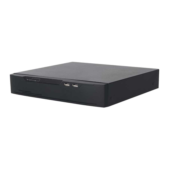
Network Video Recorder Product Structure User Manual 2 Product Structure 2.1 Front Panel Figure 2-1 NVR24 / NVR25 KB/ M O U SE BAC KU P Table 2-1 Front panel function Port Description When the NVR is operating, the PWR indicator is steady on. When the NVR is shut down, the PWR indicator is turned off. - Page 26 Network Video Recorder User Manual Product Structure NVR is shut down, the PWR indicator is turned off. Network status indicator This indicator flashes when data is transmitted. Hard disk status indicator This indicator flashes when data is transmitted. Only supports connected to an USB mouse Figure 2-3 NVR2632E8 H D D PW R...
-
Page 27: Back Panel
Network Video Recorder Product Structure User Manual NVR is shut down, the PWR indicator is turned off. Network status indicator This indicator flashes when data is transmitted. Hard disk status indicator This indicator flashes when data is transmitted. Only supports connected to an USB mouse 2.2 Back Panel Figure 2-5 NVR2508E1-P8/2508E2-P8 P OE PO RT S... - Page 28 Network Video Recorder User Manual Product Structure 图 1-1 NVR2608E1-P8C AUD IO USB3. 0 ALARM I/O Table 2-6 Real panel function Port Description POE network interfaces RJ 45 10/100/1000 Mbps adaptive Ethernet interface AUDIO OUT / Audio output / Audio input AUDIO IN Video output interface HDMI...
- Page 29 Network Video Recorder Product Structure User Manual Table 2-7 Real panel function Port Description Alarm input and alarm output./RS485 LINE OUT / Audio output / Audio input LINE IN LAN1 /LAN2 RJ 45 10/100/1000 Mbps adaptive Ethernet interface Video output interface HDMI(1/2)...
- Page 30 Network Video Recorder User Manual Product Structure LINE OUT / Audio output / Audio input LINE IN RJ 45 10/100/1000 Mbps adaptive Ethernet interface Video output interface HDMI RS232 Standard RS232 serial communication interface of the device USB 3.0 Only supports connected to 3.0 U disk E SATA External hard disk interface Power switch...
- Page 31 Network Video Recorder Product Structure User Manual Figure 2-8 WiFi model H D -O U T VG A D C -1 2 V Table 2-9 Real panel function Port Description RJ 45 10/100/1000 Mbps adaptive Ethernet interface Video output interface DC 12V Connected to an external power adapter Safe ground screw of the device...
- Page 32 Network Video Recorder User Manual Product Structure Issue: V4.3 (2019-10-21)
- Page 33 Network Video Recorder Product Structure User Manual Issue: V 4.3(2019-10-21)
-
Page 34: Important Notes
Network Video Recorder User Manual Product Structure 2.3 Important Notes Thank you for choosing the NVR. Please read the user manual carefully before using this product. The NVR is a complex system-based device. To avoid misoperations and malfunctions caused by environmental factors and human factors during installation, commission, and application, note the following points when installing and using this product: Issue: V4.3 (2019-10-21) -
Page 35: About This User Manual
Network Video Recorder Product Structure User Manual Read the user manual carefully before installing and using this product. Use Monitoring dedicated hard disks as the storage devices of the NVR with high stability and competitive price/performance ratios (the quality of hard disks sold on markets varies greatly with different brands and models). - Page 36 Network Video Recorder User Manual Product Structure Item Description HDDs or more),please refer to actual product. Power consumption <15W (excluding the hard disk) Installation precautions Note the following points when installing and operating the NVR: The power adapter of the NVR uses DC48V±20% input. Do not use the NVR when voltage is too high or too low.
-
Page 37: Install Device
Network Video Recorder Install device User Manual 3 Install device 3.1 Process Start Unpacking inspection Install hard disk Connect cable Boot device Configure and enter interface Issue: V 4.3(2019-10-21) -
Page 38: Unpacking Inspection
Network Video Recorder User Manual Install device Step 1 Check the appearance, packaging, and label of the device to ensure which no damage. Step 2 Install the hard disk and fix the hard disk on the device bracket. Step 3 Connect the device cable. Step 4 After ensuring that the device is connecting correct, connect the power and turn on the device. -
Page 39: Install Hard Disk
Network Video Recorder Install device User Manual personnel. 3.3 Install Hard Disk When installing for the first time, first check if the hard disk is installed. It is recommended to use the company recommended hard disk model 9 disk compatibility. It is not recommended to use a PC dedicated hard disk. -
Page 40: Install Four Hard Disks
Network Video Recorder User Manual Install device Figure 3-2 Install hard disk Step 4 Turn the device over, and fasten the rest two hard disk fixing screws, as shown in Figure 3-3. Figure 3-3 Install hard disk Step 5 Insert the hard disk data cable and power cable, then put on the upper cover and fasten the fixing screws. -
Page 41: Install Eight Hard Disks
Network Video Recorder Install device User Manual Figure 3-4 Installing the hard disks Hard d isk b racket Ha rd di sk Step 3 Install other hard disks following step 2. Step 4 Insert the hard disk data cable and power cable, then put on the upper cover and fasten the fixing screws. - Page 42 Network Video Recorder User Manual Install device Figure 3-6 Unscrew the screws lift the upper bracket Step 5 Insert the hard disk data cable and power cable, then put on the upper cover and fasten the fixing screws. Issue: V4.3 (2019-10-21)
-
Page 43: Basic Operations
Network Video Recorder Basic Operations User Manual 4 Basic Operations 4.1 Power on the Device Ensure that the NVR is correctly connected to a power supply, and a display is correctly connected to the high definition multimedia interface (HD-OUT) or video graphics array (VGA) port of the NVR before power-on. -
Page 44: Activation
Network Video Recorder User Manual Basic Operations Figure 4-1 Real-time video screen Users need to provide a hard disk for the NVR. The hard disk is strictly detected during device startup. If the detection result failed, the possible causes are as follows. The hard disk is new and is not formatted. - Page 45 Network Video Recorder Basic Operations User Manual Figure 4-2 Activation Table 4-1 Description of activation Name Description The default username is admin, and “admin” is super administrator. Username Password Valid password range 6-32 characters. At least 2 kinds of numbers, lower case, upper case or special characters Confirm password contained.
- Page 46 Network Video Recorder User Manual Basic Operations User can set the pattern unlock to login the device, as shown in Figure 4-3. Figure 4-3 Set pattern unlock After the pattern is unlocked, the system defaults to the pattern unlock login. If the pattern unlock is not set, you will need to input the password to login.
- Page 47 Network Video Recorder Basic Operations User Manual Figure 4-4 Set Email Set the email address, if you forget the password, you can though the email address to receive the verification, and reset the password. If the email address is not set, you can reply to the secure question or send the QR code to the seller to give the temporary password to login to the device..
- Page 48 Network Video Recorder User Manual Basic Operations Figure 4-5 Set question The user can set three questions, and if they forget the password, they can answer the question and enter the reset password interface. Question one can be set: Your favorite animal Company name of your first job The name of the first boy/girl you like The worst security question you have ever seen...
-
Page 49: Power Off The Device
Network Video Recorder Basic Operations User Manual 4.3 Power off the Device Click the main menu and choose System > Maintenance, the maintenance setting page is displaying, click Shutdown to power off the NVR. If there is a power switch on the rear panel of the NVR, you can RPM off the power switch to disconnect the NVR from the power supply. - Page 50 Network Video Recorder User Manual Basic Operations Figure 4-7 Password login page Step 3 Input the username and password. The password incorrect more than 3 times, please login again after 5 minutes. You can also power off, and power on to start on the device, input the correct password to avoid waiting five minutes. If user forget password, click Forgot password.
- Page 51 Network Video Recorder Basic Operations User Manual Figure 4-8 Modify default password ----End Issue: V 4.3(2019-10-21)
-
Page 52: Wizard
Network Video Recorder User Manual Wizard 5 Wizard Login the NVR, the wizard is showing on live video, click Start Wizard, the pop-up window will show as Figure 5-1. Figure 5-1 Wizard Issue: V4.3 (2019-10-21) - Page 53 Network Video Recorder Wizard User Manual Figure 5-2 Wizard of network Step 1 Set the parameter, the details please refer to Table 5-1. Table 5-1 Network parameter Parameter Description Configuration DHCP Enable DHCP, the device will [Setting method] obtain the IP address from the Enable DHCP server.
- Page 54 Network Video Recorder User Manual Wizard Parameter Description Configuration Subnet mask Set the subnet mask of device [Setting method] Manual [Default value] 255.255.255.0 Gateway If the user wants to access device, [Setting method] he must set that Manual [Default value] 192.168.0.1 Obtain DNS [Setting method]...
- Page 55 Network Video Recorder Wizard User Manual Step 2 Click to view the basic information about device, as shown in Figure 5-3. Figure 5-3 Wizard of date and time Choose date format and time format from drop-down list. Click to synchrony time from network. Disable the NTP-Sync, set time manually.
- Page 56 Network Video Recorder User Manual Wizard Figure 5-4 Wizard of time zone Step 4 Click DST, enable the DST, set start and end time. Select offset time from drop-down list. Step 5 Click to enter the adding camera wizard, as shown in Figure 5-5. Issue: V4.3 (2019-10-21)
- Page 57 Network Video Recorder Wizard User Manual Figure 5-5 Wizard of adding camera The details of adding camera please refer to chapter 7.3. Step 6 Click to enter wizard of disk, as shown in Figure 5-6. Issue: V 4.3(2019-10-21)
- Page 58 Network Video Recorder User Manual Wizard Figure 5-6 Wizard of disk You can view the general information of disk. You can also format the disk. Step 7 Click to enter wizard of P2P, as shown in Figure 5-7 Issue: V4.3 (2019-10-21)
- Page 59 Network Video Recorder Wizard User Manual Figure 5-7 P2P Step 8 Enable the P2P, user can use mobile devices to manage the NVR by scanning the P2P ID, if the mobile phone has loaded the InView Pro 4(search the APP at App Store or Google Play). Step 9 Click to enter the wizard of resolution , as shown in Figure 5-8.
- Page 60 Network Video Recorder User Manual Wizard Figure 5-8 Wizard of resolution Step 10 Click to end the wizard, tick the Not show this window next time, wizard would not show at next time. Reopen wizard at system >user >advance setting. Issue: V4.3 (2019-10-21)
-
Page 61: Quick Navigation
Network Video Recorder Quick Navigation User Manual 6 Quick Navigation After the NVR operation screen is displaying, move the cursor to the down most position of the NVR screen. The NVR floating menu bar is displaying. Click in the left of NVR floating menu bar. The quick home menu is showing. The quick home menu provides Playback, System and Power(Shutdown, Reboot and Logout) as shown in Figure 6-1. - Page 62 Network Video Recorder User Manual Quick Navigation : Auto SEQ. click icon, the layout dwell on screen is enabled, for how to set the dwell on, please see chapter 7.7.5. : Audio. Click icon, the audio setting screen is displaying, which you can choose the channel and adjust the volume.
-
Page 63: Alarm Message
Network Video Recorder Quick Navigation User Manual 6.1 Alarm message : Clean alarm, click icon and clean the current alarm actions like vioce and external alarm out. : Information, click icon and the genreal information would show, like network, system, channel and disk, as shown in Figure 6-5. -
Page 64: Real Time Video Bar
Network Video Recorder User Manual Quick Navigation 6.2 Real Time Video Bar Click realtime image, the quick setting will show as figure. Record: click the icon and start to record video. Click again to end record. Instant playback: click the icon, the window will play previous five minutes record video. is the time bar of playback. - Page 65 Network Video Recorder Quick Navigation User Manual : Zoom in, click zoom in, roll the mouse wheel to zoom in and zoom out. Right-click to exit the zooming. : Image, click the icon ,as shown in Figure 6-7. Select scene, and drag cursor to adjust value of brightness, sharpness, contrast and saturation.
-
Page 66: Playback
Network Video Recorder User Manual Quick Navigation Figure 6-8 Modify device parameter 6.3 Playback Playback refers to playing back a video. Click in the quick navigation bar to access the playback screen, as shown in Figure 6-9. Issue: V4.3 (2019-10-21) - Page 67 Network Video Recorder Quick Navigation User Manual Figure 6-9 Playback screen The toolbar at the bottom of the playback screen is described as follows: : Layout. : Reversed, pause/play, stop. :30s backward, 30s farward. :Triple speed, it supports up to 32 times to playback. : Zoom.
- Page 68 Network Video Recorder User Manual Quick Navigation : Start and end backup. Click the icon, the video backup starts, select the video and click the icon again. The backup type shows, click save, then saving the file pop-up windows would show as Figure 6-10 .
-
Page 69: Time Search
Network Video Recorder Quick Navigation User Manual Figure 6-11 Batch backup : Type of time bar, recording video can show 6.3.1 Time Search Search refers to searching for a video by date and time. Operation Description Click in the quick navigation bar to access the search screen, as shown in Figure 6-12. Issue: V 4.3(2019-10-21) -
Page 70: Picture Grid
Network Video Recorder User Manual Quick Navigation Figure 6-12 Time Search screen Operation Steps Step 1 Select a camera in the camera list on the left side of the search screen. The video view of the selected camera is displaying in the play window. Step 2 Select a date in the calendar on the light-down side of the search screen. -
Page 71: Event
Network Video Recorder Quick Navigation User Manual Figure 6-13 Picture grid screen Operation Steps Step 1 Select a camera in the camera list on the left side of the picture grid screen. Videos shot by the camera in the earliest time range on the current day are displayed as thumbnails in the window on the right side. -
Page 72: Backup
Network Video Recorder User Manual Quick Navigation Figure 6-14 Event screen Operation Steps Step 1 Select a camera in the camera list on the left. Step 2 Set start and end time. Step 3 Tick the alarm type, such as alarm in, motion alarm, block alarm, video loss and intelligent analysis. -
Page 73: Thermal Temperature
Network Video Recorder Quick Navigation User Manual Figure 6-15 Backup screen You can view the detail information of backup. Click delete button to quit the download. ----End 6.4 Thermal Temperature NOTE The thermal temperature function is only carried by some devices. If the current device does not have the function, please ignore it. - Page 74 Network Video Recorder User Manual Quick Navigation Figure 6-16 Temperature Parameters interface Step 4 Set the parameters according to Table 6-1. Table 6-1 Temperature parameters Parameter Description Setting Open Temperature Enable temperature measure. Measure Temperature Unit Celsius and Fahrenheit [Setting method] temperature units are available.
- Page 75 Network Video Recorder Quick Navigation User Manual Parameter Description Setting Cavity The cavity temperature of Temperature camera. Correction Correction coefficient is refer [Setting method] Coefficient to the deviation of measured Enter a value manually. object temperature and [Default value] actual temperature. 0.00 For example: 1.
- Page 76 Network Video Recorder User Manual Quick Navigation Parameter Description Setting Custom Colors Enable to custom the color, [Setting method] there are nine colors chosen. Enable or disable [Default value] disable Area Temperature There are three types of area [Setting method] Type temperature.
- Page 77 Network Video Recorder Quick Navigation User Manual Figure 6-17 Advanced parameter Table 6-2 Advanced parameters Parameter Description Setting Dimming Mode There are auto and manual [Setting method] modes. It will show on Select a value from the temperature item. drop-down list box. [Default value] Auto Greater Prominent...
-
Page 78: Temperature Area
Network Video Recorder User Manual Quick Navigation Parameter Description Setting Section Prominent Enable that, the image will [Setting method] show the setting color if the Enter a value manually. temperature is between Choose one color to minimum and maximum show. temperature. - Page 79 Network Video Recorder Quick Navigation User Manual Figure 6-18 Temperature area and alarm configuration Step 2 Set the parameters according to Table 6-3 Table 6-3 Temperature area and alarm configuration Parameter Description Setting Channel [Setting method] Select a value from the drop-down list box.
- Page 80 Network Video Recorder User Manual Quick Navigation Parameter Description Setting PTZ Area(only Choose or set the preset, adjust Set the preset manually, use for PTZ the camera with PTZ keyboard. or select an existing preset cameras) in the drop-down list. The all presets can set 20 areas to alarm Enable...
- Page 81 Network Video Recorder Quick Navigation User Manual Parameter Description Setting Maximum Alarm The maximum value of the [Setting method] Value alarm range, if the alarm value Enter a value manually. is exceeded, no alarm will be [Default value] generated. 60.00 Emission Rate The emission rate is the [Setting method]...
-
Page 82: Schedule Linkage
Network Video Recorder User Manual Quick Navigation Delete a temperature area: 1. Select an area ID. 2. Click the temperature area and right-click. 3. Remove the tick of area ID. 4. Click Apply, the message “Apply success” is displayed, the temperature area is deleted successfully. - Page 83 Network Video Recorder Quick Navigation User Manual Step 3 Enable “Alarm Record”, “E-mail” button. Step 4 Set schedule linkage. Figure 6-20 Schedule Method 1: Click left mouse button to select any time point within 0:00-24:00 from Monday to Sunday as shown in Figure 6-19. Method 2: Hold down the left mouse button, drag and release mouse to select the alarm time within 0:00-24:00 from Sunday to Saturday.
-
Page 84: Advanced
Network Video Recorder User Manual Quick Navigation 6.4.4 Advanced Operation Procedure Step 1 Choose Thermal > Advanced to enter the advance interface, as shown in Figure 7-1. Figure 6-21 Advanced Step 2 Select the temperature collection interval from the drop-list. Step 3 Click Apply. -
Page 85: Face Defection
Network Video Recorder Quick Navigation User Manual Figure 6-22 Inquire Step 2 Choose the channel is thermal camera. Step 3 Set the start and end time. Step 4 Choose the area, which is set at the temperature area interface. The default area is 0(full screen). -
Page 86: Face Comparison
Network Video Recorder User Manual Quick Navigation 6.5.1 Face Comparison Click the icon at quick navigation bar, enter to the face comparison interface, as shown in Figure 6-23. Figure 6-23 Face comparison interface Table 6-4 Face comparison Description Camera list Menu Live video Real time comparison area, the snapshot picture of person will compare with the... -
Page 87: Face Search
Network Video Recorder Quick Navigation User Manual Snapshot in real time video, put the cursor on picture such as , you can add it to face library, or face search. The cursor on area 6 and the pictures is not update, move the mouse so that the pictures can be shown in time. 6.5.2 Face Search Figure 6-24 Face search interface Table 6-5 Face comparison... -
Page 88: Face Library
Network Video Recorder User Manual Quick Navigation 6.5.3 Face Library Figure 6-25 Face library Table 6-6 Face library Description Add a new face library Edit or delete the face library. Add or delete the personnel. Add personnel as shown in Figure 7-1. Import or export the face library. -
Page 89: Comparison Configuration
Network Video Recorder Quick Navigation User Manual Figure 6-26 Person enroll 6.5.4 Comparison Configuration In comparison configuration interface, click to set the comparison strategy, enable the face matching, select face database, set similarity, tick the linkage mode, set schedule of enable face comparison, as shown in Figure 6-27. - Page 90 Network Video Recorder User Manual Quick Navigation Figure 6-27 Comparison configuration Issue: V4.3 (2019-10-21)
-
Page 91: Attendance
Network Video Recorder Quick Navigation User Manual 6.6 Attendance The function only be used for NVR2604E1-P4C-J and NVR2608E1-P8C-J 6.6.1 Attendance Data Click to enter attendance data interface, as shown in Figure 6-28. Figure 6-28 Attendance data Operation Steps Step 1 Tick the attendance library. Step 2 Choose time mode, such as today, this week, this month and custom time. -
Page 92: Attendance Management
Network Video Recorder User Manual Quick Navigation 6.6.2 Attendance Management In attendance management, user can set attendance rule, library and check point, as shown in Figure 6-29. Figure 6-29 Attendance rule settings Operation Steps Step 1 Set start work time and end work time. Step 2 Tick the workday Step 3 Set valid time of check in and check out. - Page 93 Network Video Recorder Quick Navigation User Manual Figure 6-30 Attendance library Step 2 Tick the library and click Add to add to attendance library. If you want to modify the library. Step 3 click to enter the face database management to modify parameter.
- Page 94 Network Video Recorder User Manual Quick Navigation Figure 6-31 Attendance check point setting Step 2 Click to edit check point setting, as shown in Figure 6-32 Issue: V4.3 (2019-10-21)
- Page 95 Network Video Recorder Quick Navigation User Manual Figure 6-32 Check point Step 3 Enable the function, set similarity and tick the library, all face detection cameras can be set the check points Step 4 Click OK to save the setting. Issue: V 4.3(2019-10-21)
-
Page 96: Ui System Setting
Network Video Recorder User Manual UI System Setting 7 UI System Setting 7.1 Channel Information Click the will show as Figure 7-1, tick the Channel or Encode, the information will show in live video screen. Figure 7-1 Channel information 7.2 Main Menu Right-click on UI screen, the main menu as shown in Figure 7-2. - Page 97 Network Video Recorder UI System Setting User Manual Issue: V 4.3(2019-10-21)
-
Page 98: Channel Management
Network Video Recorder User Manual UI System Setting 7.3 Channel Management IP cameras can directly connect to input channels of the NVR by plugging in POE port. When IP cameras are insufficient, the NVR can automatically searches for and adds IP cameras or manually add cameras in the same Local Area Network (LAN). -
Page 99: Add Camera Automatically
Network Video Recorder UI System Setting User Manual 7.3.1.1 Add Camera Automatically The NVR can add automatically cameras to the camera list. Operation Methods Method 1: Click button, the cameras these are the same local area network with NVR will show in list, input username and password (the default value both are admin )click , the cameras in the list would be added to channels directly. -
Page 100: Delete Camera
Network Video Recorder User Manual UI System Setting Figure 7-4 Add camera screen Step 2 Input IP address, port, user name and password of camera. Step 3 Select a protocol from the drop-down list. Remote channel is only used for thermal imaging cameras. -
Page 101: Operate Camera
Network Video Recorder UI System Setting User Manual Figure 7-1 Delete confirmation message Step 2 Click , the camera is deleted successfully. 7.3.1.4 Operate Camera At camera list, click to operate camera as shown in Figure 7-2, user can update, reboot and reset the camera immediately. -
Page 102: Encode Parameter
Network Video Recorder User Manual UI System Setting Step 4 Click Reset, message “Are you sure to reset? ”would show, user can enable the retain IP address function. click to rebset the camera. Step 5 Tick the cameras with non-onvif protocol and cameras are online, click Update to update all cameras at once. -
Page 103: Sensor Setting
Network Video Recorder UI System Setting User Manual Step 2 Select stream information. Step 3 Select encode type, resolution, frame rate, bitrate type and bitrate size from the drop-down lists. Step 4 Click and select channels or tick all, then click to apply the parameter settings to cameras in selected channels , click to save encode parameter... -
Page 104: Osd Settings
Network Video Recorder User Manual UI System Setting Sharpness: it indicates picture’s clarity. Contrast: it refers to the brightest white and darkest black in an image. Saturation: it indicates brilliance of the picture color. Other parameters are sensor settings of IP cameras, like scene, exposure, white balance, day- night, noise reduction, enhance image, zoom focus, etc. -
Page 105: Privacy Zone
Network Video Recorder UI System Setting User Manual Figure 7-6 OSD setting screen Operation Steps Step 1 Select a channel from the drop-down list of channel. Step 2 Click next to Time to enable or disable OSD time setting. Step 3 Click next to Name to enable or disable OSD channel setting. - Page 106 Network Video Recorder User Manual UI System Setting Figure 7-7 Privacy zone screen Operation Steps Step 1 Select a channel from the drop-down list of channel. Step 2 In the video window, hold down and drag the left mouse button to draw a privacy area. Step 3 Click and select channels or tick all, then click to apply the privacy...
-
Page 107: Record Setting
Network Video Recorder UI System Setting User Manual 7.4 Record Setting Set the Record Schedule, view the disk capacity, examine the record’ status. 7.4.1 Record Schedule Operation Description Click Record in the main menu or click the record page of any function screen in the main menu to access the record schedule screen, as shown in Figure 7-8. -
Page 108: Disk
Network Video Recorder User Manual UI System Setting NOTE When you select time by dragging the cursor, the cursor cannot move out of the time area. Otherwise, no time would be selected. The selected area is blue. The default is all week. Method 2: Click in the record schedule page to select the whole day or whole week. -
Page 109: Raid
Network Video Recorder UI System Setting User Manual Figure 7-9 Disk screen Step 2 Click Format. The message “Are you sure to format disk? Your data will be lost” is displaying. Step 3 Click , and the disk would be formatted. Step 4 Record expiration setting. - Page 110 Network Video Recorder User Manual UI System Setting RAID5 at least 3 disks can be created. RAID6 at least 4 disks can be created. RAID10 at least 4 disks can be created. Create hot spare disk need more one disk or double basic disks. The capacity of disks are better same for efficient using.
- Page 111 Network Video Recorder UI System Setting User Manual Figure 7-11 S.M.A.R.T Issue: V 4.3(2019-10-21)
-
Page 112: Alarm Management
Network Video Recorder User Manual UI System Setting 7.5 Alarm Management Set the General alarm information, Motion Detection, Video Loss, Intelligent Analysis, Alarm In and Abnormal Alarm in alarm management screen. 7.5.1 General Step 1 Click Alarm in the main menu (or click the alarm page of any function screen in the main menu) to access the alarm management screen, as shown in Figure 7-12. -
Page 113: Motion Detection
Network Video Recorder UI System Setting User Manual 7.5.2 Motion Detection The NVR will send motion detection alarm while something moving in the specific view of camera. Operation Description Step 1 Click Motion Detection in the main menu or menu of the alarm management screen and choose Motion Detection to access the Motion Detection screen, as shown in Figure 7-13. - Page 114 Network Video Recorder User Manual UI System Setting Figure 7-14 Motion detection area setting screen Area : 1. Hold down and drag the left mouse button to draw a motion detection area. 2. Select a value from the drop-down list next to Sensitivity. Step 6 Click Schedule page to access the schedule screen.
-
Page 115: Video Loss
Network Video Recorder UI System Setting User Manual 7.5.3 Video Loss If a camera is disconnected to NVR, it will trigger video loss alarm. Operation Description Click Video Loss in the main menu or menu of the alarm management screen and choose video Loss to access the video loss screen, as shown in Figure 7-15. -
Page 116: Intelligent Analysis
Network Video Recorder User Manual UI System Setting ----End 7.5.4 Intelligent Analysis Operation Description Step 1 Click Intelligent Analysis in the main menu or menu of the alarm management screen and choose Intelligent Analysis to access intelligent analysis screen, as shown in Figure 7-6. Figure 7-16 Intelligent Analysis screen Step 2 Select one action to set the alarm.( perimeter, single virtual fence, double virtual fences, object left, signal bad, advanced) -
Page 117: Alarm In
Network Video Recorder UI System Setting User Manual Step 7 For details, please see Figure 7-8Step 4 Set the record schedule. Step 8 Click and select a channel, then click to apply the parameter settings to cameras in selected channels, click to save video loss settings. - Page 118 Network Video Recorder User Manual UI System Setting NC: Normal close the alarm NO: Normal open the alarm Step 4 Set name. Step 5 Enable the event actions include: buzzer, alarm out, push message, pop up message, send E-mail and post recording. Step 6 Click Schedule page to access the schedule screen.
-
Page 119: Abnormal Alarm
Network Video Recorder UI System Setting User Manual 7.5.6 Abnormal Alarm Camera tamper means that the NVR would send alarm notification while objects cover IP cameras. Operation Description Step 1 Click Abnormal Alarm in the main menu or menu of the alarm management screen and choose Abnormal Alarm to access the abnormal alarm screen, as shown in Figure 7-18. -
Page 120: Network Management
Network Video Recorder User Manual UI System Setting 7.6 Network Management Set the Network Parameter, 802.1X, DDNS, E-mail, Port Mapping, P2P, IP Filter and SNMP in the network management screen. Operation Description Step 1 Click Network in the main menu (or click the network page of any function screen in the main menu) to access the network management screen, as shown in Figure 7-19. -
Page 121: Port
Network Video Recorder UI System Setting User Manual 7.6.1.1 IP Operation Steps Step 1 Click next to DHCP to enable or disable the function of automatically getting an IP address. The function is disabled by default. Step 2 If the function is disabled, click input boxes next to IP, Subnet mask, and Gateway to set the parameters as required. -
Page 122: Poe
Network Video Recorder User Manual UI System Setting Figure 7-20 Port setting screen Step 2 Set the web port, data port and client port. Step 3 Click to save port settings. ----End 7.6.1.3 POE Operation Steps Step 1 Click POE page to access the POE setting screen, as shown in Figure 7-21. Issue: V4.3 (2019-10-21) -
Page 123: Wifi Parameter
Network Video Recorder UI System Setting User Manual Figure 7-21 POE screen Step 2 The NVR will deploy IP addresses to the cameras which connect POE immediately. Step 3 Click to set POE camera IP address successfully. ----End 7.6.1.4 WiFi Parameter Operation Steps Step 1 Click WiFi Parameter page to access the WiFi Parameter setting screen, as shown in Figure 7-21. -
Page 124: Wifi Network
Network Video Recorder User Manual UI System Setting Figure 7-22 WiFi Parameter Step 2 Set the parameters of WiFi。 Step 3 Click to set POE camera IP address successfully. BSDID, default value of the device, cannot be changed. SSID, the name can be changed to facilitate customer search. WiFi channel;... -
Page 125: 105
Network Video Recorder UI System Setting User Manual Figure 1-1 WiFi network ----End 7.6.2 802.1 X Operation Steps Step 1 Click next to 802.1 X to enable or disable the function .The default is disabled. Issue: V 4.3(2019-10-21) -
Page 126: Ddns
Network Video Recorder User Manual UI System Setting Figure 7-23 802.1 X Step 2 Input the user and password of 802.1X, the account is created by user. Step 3 Click to save the settings. The visitor to view the NVR need to input account to certify. -
Page 127: E-Mail
Network Video Recorder UI System Setting User Manual Figure 7-24 DDNS setting screen Step 3 Select a required value from the protocol drop-down list. Step 4 Set domain name, input user and password. Step 5 Click to check the domain name. Step 6 Click to save DDNS network settings An external network can access the NVR via an address that is set in the DDNS settings. - Page 128 Network Video Recorder User Manual UI System Setting Figure 7-25 E-mail setting screen Step 2 Set SMTP server and SMTP server port manually. Step 3 Input E-mail sender, user name and password manually. Step 4 Set E-mail for receive alarm. the message “Mail has been sent, please check” is displaying.
-
Page 129: Port Mapping
Network Video Recorder UI System Setting User Manual 7.6.5 Port Mapping Operation Steps Step 1 Click Port Mapping in the main menu or menu of the network management screen and choose Port Mapping to access the port mapping screen, as shown in Figure 7-26. Figure 7-26 Port mapping setting screen Step 2 Select UPnP enable type. -
Page 130: Ip Filter
Network Video Recorder User Manual UI System Setting Operation Steps Step 1 Click P2P in the main menu or menu of the network management screen and choose P2P to access the P2P screen, as shown in Figure 7-27. Figure 7-27 P2P screen Step 2 Click to enable the P2P function. - Page 131 Network Video Recorder UI System Setting User Manual Operation Steps Step 1 Click IP Filter in the main menu or menu of the network management screen and choose IP Filter to access the IP filter screen, as shown in Figure 7-28. Figure 7-28 IP Filter setting screen Step 2 Click next to IP Filter to enable the function of IP Filter.
-
Page 132: Snmp
Network Video Recorder User Manual UI System Setting Figure 7-29 IP Address Segment screen Step 5 Enter value manually for start IP address, end IP address. Step 6 Click . The system saves the settings. The black and white lists IP segment listed in the black (white) list. - Page 133 Network Video Recorder UI System Setting User Manual Figure 7-30 SNMP settings screen Step 2 Click next to SNMPV 1 to enable the function . The interface is shown as Figure 7-31. Figure 7-31 SNMPV 1/2 interface Step 3 Input the parameters of protocol. Step 4 Click to save settings or click to cancel settings.
-
Page 134: System Management
Network Video Recorder User Manual UI System Setting 7.7 System Management View the device Information and set General information, User, Security Center, Auto Sequence, Logs, Maintenance and Auto Restart for the system setting. Operation Description Click System in the main menu (or click the system page of any function screen in the main menu) to access the system setting screen, as shown in Figure 7-32. -
Page 135: General
Network Video Recorder UI System Setting User Manual Figure 7-33 Information interface 7.7.2 General 7.7.2.1 System Operation Steps Step 1 Click General in the main menu or menu of the system management screen and choose General to access the system screen, as shown in Figure 7-34. Issue: V 4.3(2019-10-21) -
Page 136: Date And Time
Network Video Recorder User Manual UI System Setting Figure 7-34 system setting screen Step 2 Enter device name for selected device. Step 3 Select a proper resolution from the output resolution drop-down list. Step 4 Select a required language from the Language drop-down list. Step 5 Click to save settings. -
Page 137: Time Zone
Network Video Recorder UI System Setting User Manual Figure 7-35 Date and Time setting screen Step 2 Select required format from the Date Format and time format drop-down list. Step 3 Click next to NTP Sync to disable time synchronization. Time synchronization is enabled by default. -
Page 138: Dst
Network Video Recorder User Manual UI System Setting Figure 7-36 Time zone setting screen Step 2 Select a required time zone from the Time Zone drop-down list. Step 3 Click to save settings. ----End 7.7.2.4 DST When the DST start time arrives, the device time automatically goes forward one hour (offset time). -
Page 139: User
Network Video Recorder UI System Setting User Manual Figure 7-37 DST setting screen Step 2 Click next to DST to enable DST. Step 3 Select start time, end time, offset time from the drop-down list respectively, that basis on the local rules. Step 4 Click to save settings. -
Page 140: User
Network Video Recorder User Manual UI System Setting 7.7.3.1 User Operation Steps Step 1 Click User in the main menu or menu of the system management screen and choose User to access the user screen, as shown in Figure 7-38. Figure 7-38 User management screen Step 2 Add or delete a user. - Page 141 Network Video Recorder UI System Setting User Manual Figure 7-39 Add user screen Input a username, password and confirm password. The password should include letter, character and number, at least two types. The password should be 6~32 characters. Step 3 Select a Group from the drop-down list box. Step 4 Select a Change password reminder value from the drop-down list box.
-
Page 142: Advance Setting
Network Video Recorder User Manual UI System Setting 7.7.3.2 Advance Setting Operation Steps Step 1 Click User in the main menu or menu of the system management screen and choose Adv Setting to access the user screen, as shown in Figure 9-8. Figure 7-40 Advance setting screen Step 2 Enable or disable Auto login, Password double authentication, Boot Wizard. -
Page 143: Password
Network Video Recorder UI System Setting User Manual 7.7.4.1 Password Operation Steps Step 1 Click Security Center in the main menu or menu of the system management screen and choose Password to access the modify password screen, as shown in Figure 7-41. Figure 7-41 Password modification screen Step 2 Input the correct old password, new password, and confirm password. -
Page 144: Pattern Unlock
Network Video Recorder User Manual UI System Setting 7.7.4.2 Pattern Unlock Operation Steps Step 1 Click Security Center in the main menu or menu of the system management screen and choose Pattern Unlock to access the modify pattern unlock screen, as shown in Figure 7-42. Figure 7-42 Pattern unlock screen Step 2 Input the password, click Setting Pattern to set an new pattern unlock. -
Page 145: Secure Question
Network Video Recorder UI System Setting User Manual Figure 7-43 Secure Email Step 1 Input the password of NVR. Step 2 Set the Email which will receive email of the verification code. Step 3 Click to save setting. ----End 7.7.4.4 Secure Question Set the questions to create new password, as shown in Figure 7-43. -
Page 146: Auto Sequence
Network Video Recorder User Manual UI System Setting Figure 7-44 Secure question Step 1 Input the password of NVR. Step 2 Choose the question from drop-down list. Step 3 Input the answer, click to save setting. ----End 7.7.5 Auto Sequence Set video mode, dwell time in display screen. -
Page 147: Auxliary Screen
Network Video Recorder UI System Setting User Manual Figure 7-45 Auto Sequence screen Step 2 Set mode of display. Select a display mode from the SEQ drop-down list. Step 3 Select dwell time from the SEQ Dwell time drop-down list(the display screen will loop play the real time video according to setting time). - Page 148 Network Video Recorder User Manual UI System Setting Figure 7-46 Auxiliary screen Step 3 Set the Output Resolution, Decoding Ability(main + auxiliary), Layout Mode, Display Channel. Step 4 Enable tour to set Auto Sequence of auxiliary scree as shown in . Issue: V4.3 (2019-10-21)
-
Page 149: Logs
Network Video Recorder UI System Setting User Manual Figure 7-47 Auto sequence of auxiliary screen Step 5 Click to save settings. The auxiliary screen shows different channels with main screen, and the auto sequence show all channels.. 7.7.7 Logs Search for logs information and export the information. Operation Steps Step 1 Click Logs in the main menu or menu of the system management screen and choose Logs to access the log screen, as shown in Figure 7-48. -
Page 150: Maintenance
Network Video Recorder User Manual UI System Setting Figure 7-48 Log screen Step 2 Set the logs start date, end date, start time and end time on log screen. Step 3 Select logs type from the drop-down list. Step 4 Click to query logs. -
Page 151: Auto Restart
Network Video Recorder UI System Setting User Manual Figure 7-49 Maintenance screen Step 2 Click Shutdown , Reboot , Logout, Exit system, Reset or update to operate NVR if you need. Step 3 Click import configuration or export configuration to view the message “ Are you sure to import the configuration?”... - Page 152 Network Video Recorder User Manual UI System Setting Figure 7-50 Auto restart screen Step 2 Enable the function, restart time is showing as figure Step 3 Restart the NVR per day, week or month. Step 4 Select the restart time from the drop-down list. ----End Issue: V4.3 (2019-10-21)
-
Page 153: Web Quick Start
Network Video Recorder WEB Quick Start User Manual 8 WEB Quick Start 8.1 Activation If you don’t set the password at UI interface, user need activate the device, as shown in Figure 8-1 Activation Step 1 Set the password, confirm the password. Step 2 Input the channel password. -
Page 154: Login And Logout
Network Video Recorder User Manual WEB Quick Start Figure 8-3 Question If you don’t to set the email or question, you can skip the steps. 8.2 Login and Logout You must use below Firefox 53 or below Chrome 45 to access the Web interface. Otherwise, the interface functions cannot be used normally. - Page 155 Network Video Recorder WEB Quick Start User Manual Go to the experimental features management page. Enable NAPAPI Mac, Windows. Click Enable (NPAPI plugin is enabled). Re-launch Chrome. Here we take IE 10 as an example for videos viewing. Login Step 1 Open IE browser, enter the IP address of the NVR (default value: 192.168.0.121) in the address box, and press Enter.
- Page 156 Network Video Recorder User Manual WEB Quick Start The default user name and password both are admin. The password incorrect more than 3 times, please login again after 5 minutes. User can change the system display language on the login page. The modify password page pop-up window would show when login the NVR for the first time.
- Page 157 Network Video Recorder WEB Quick Start User Manual Logout To logout of the system, click in the upper right corner of the homepage. The pop-up message shows “Do you want to exit?” Click and the login page will display. Homepage Layout NVR allows you to use the Web interface in a PC for implementation of such functions as live video, playback, retrieval, setting, image parameters access, configuration, PTZ control and so on.
- Page 158 Network Video Recorder User Manual WEB Quick Start Alarm Alarm notification. User can tick pop-up message to monitor, system alarm and channel alarm. Logout button User can click Logout to exit the current account and return to the login interface. Help Help for running environment, plug-in installation and activation.
-
Page 159: Browsing Videos
Network Video Recorder WEB Quick Start User Manual 8.3 Browsing Videos 8.3.1 Browsing Real-Time Videos You can browse real-time videos in the web management system. Preparation To ensure that real-time videos can be played properly, user must perform the following operations when you log in to the web management system for the first time: Step 1 Open Internet Explorer. -
Page 160: Live Video
Network Video Recorder User Manual WEB Quick Start Figure 8-9 Configuring ActiveX controls and plug-ins Step 3 Download and install the player control as prompted. During installing, you need to close the browser. If the repair tips displayed when installing the control , close the browser and continue the installation, reopen the login page when the control is installed. -
Page 161: Channel Operation
Network Video Recorder WEB Quick Start User Manual Figure 8-10 Real-time videos interface ----End 8.3.3 Channel Operation Descriptions Channel operation includes snapshot, record, stream switch and audio on/off. Table 8-2describes the operations. Table 8-2 Descriptions of homepage Buttons Button description How to operate Snapshot Click button to take snapshots of the current image. -
Page 162: Ptz Control And Setting
Network Video Recorder User Manual WEB Quick Start ----End 8.3.4 PTZ Control and Setting Descriptions The PTZ control and setting function applies only to Network Dome or camera connected to an external PTZ. PTZ Setting If a Network Dome or a camera connected to PTZ had been added to the NVR channel, user can control the PTZ rotation to adjust their shooting angle when you are viewing the video. - Page 163 Network Video Recorder WEB Quick Start User Manual Figure 8-11 PTZ control interface Table 8-3 Device parameters Buttons Button description How to operate Direction key Click button to control omni-directional movement of the PTZ. Speed slider Drag the slider to adjust the value of PTZ rotation speed.
-
Page 164: Sensor Setting
Network Video Recorder User Manual WEB Quick Start Buttons Button description How to operate Zoom in Click buttons to adjust the focal length. Zoom out Iris+ Click buttons to adjust the aperture. Iris- Far focus Click buttons to adjust the focal length. Near focus Auto focus Click button to focus automatically. - Page 165 Network Video Recorder WEB Quick Start User Manual Figure 8-12 Image parameter interface Table 8-4 Device parameters Buttons Button description How to operate Brightness Click button to adjust the image brightness. Sharpness Click button to adjust the image definition. Contrast Click button to adjust the transparency of the image.
-
Page 166: Layout
Network Video Recorder User Manual WEB Quick Start Buttons Button description How to operate Saturation Click button to adjust the chromatic purity of the image. Click more will be access to system sensor setting. As shown in Figure 8-13, more detail please refer to chapter Figure 4-7. -
Page 167: Playback
Network Video Recorder WEB Quick Start User Manual 8.4 Playback 8.4.1 Video Playback Video playback refers to playing of videos stored in local hard disks. Procedure Step 1 Click in the function navigation bar, the video playback interface is displayed, as shown in Figure 8-14. - Page 168 Network Video Recorder User Manual WEB Quick Start After a device and date are selected, video information is displayed below the video pane. The time scale above the file axis shows the different time points of video recording. The time in blue in the middle is the time of the video playing.
-
Page 169: Alarm Search
Network Video Recorder WEB Quick Start User Manual : user can operate the record as same as live video. ----End 8.5 Alarm Search You can search for channel alarm and system alarm in the alarm search interface. 8.5.1 Channel Alarm Procedure Step 1 Click in the function navigation bar, the channel alarm interface is displayed, as... - Page 170 Network Video Recorder User Manual WEB Quick Start Figure 8-16 Channel alarm interface Step 2 Click at the top right conner, select the channel and type, set start time and end time, as shown in Figure 8-17. Figure 8-17 Set channel alarm Step 3 Click Search, the result will be displayed as shown in Figure 8-18.
-
Page 171: System Alarm
Network Video Recorder WEB Quick Start User Manual Figure 8-18 Channel alarm result Click to select the page of alarm list. shows the rows shown in every page. ----End 8.5.2 System Alarm Procedure Step 1 Click System Alarm in the channel alarm interface, the system alarm is displayed, as shown in Figure 8-19. - Page 172 Network Video Recorder User Manual WEB Quick Start Figure 8-19 System alarm result Step 2 Click at the top right conner, set the channel, type(alarm in and other), start time and end time, as shown in Figure 8-20. Figure 8-20 Search system alarm Step 3 Click Search, the result will be displayed.
-
Page 173: Face Recognition
Network Video Recorder WEB Quick Start User Manual 8.6 Face Recognition The function is only applicable for NVR2604E1-P4C-J and NVR2608E1-P8C-J 8.6.1 Face Comparison Click the icon at quick navigation bar, enter to the face comparison interface, as shown in Figure 8-21. Figure 8-21 Face comparison interface Table 8-5 Face comparison Description... -
Page 174: Face Search
Network Video Recorder User Manual WEB Quick Start Live video Real time comparison area, the snapshot picture of person will compare with the face library’s information, the result show in this area. Layout Snapshot in real time video, put the cursor on picture such as , you can add it to face library, or face search. -
Page 175: Face Library
Network Video Recorder WEB Quick Start User Manual more precise range. The detail information of chosen picture, the default is the first picture of page. Play video of snapshot, it will play a 30-second video before and after the snapshot,. 8.6.3 Face Library Figure 8-23 Face library Table 8-7 Face library... -
Page 176: Comparison Configuration
Network Video Recorder User Manual WEB Quick Start Figure 8-24 Person enroll 8.6.4 Comparison Configuration In comparison configuration interface, click to set the comparison strategy, enable the face matching, select face database, set similarity, tick the linkage mode, set schedule of enable face comparison, as shown in Figure 8-25. -
Page 177: Attendance
Network Video Recorder WEB Quick Start User Manual Figure 8-25 Comparison configuration 8.7 Attendance The function is only applicable for NVR2604E1-P4C-J and NVR2608E1-P8C-J 8.7.1 Attendance Data Click to enter attendance data interface, as shown in Figure 8-26. Issue: V 4.3(2019-10-21) -
Page 178: Attendance Management
Network Video Recorder User Manual WEB Quick Start Figure 8-26 Attendance data Operation Steps Step 1 Tick the attendance library. Step 2 Choose time mode, such as today, this week, this month and custom time. Step 3 Choose search type, such as attendance summary and attendance details. Step 4 Click search, the result will show in interface. - Page 179 Network Video Recorder WEB Quick Start User Manual Figure 8-27 Attendance rule settings Operation Steps Step 1 Set start work time and end work time. Step 2 Tick the workday Step 3 Set valid time of check in and check out. Step 4 Click Save to save the setting.
- Page 180 Network Video Recorder User Manual WEB Quick Start Figure 8-28 Attendance library Step 2 Tick the library and click Add to add to attendance library. If you want to modify the library, please enter to library interface to change parameters.. Step 3 click to enter the face database management to modify parameter.
- Page 181 Network Video Recorder WEB Quick Start User Manual Figure 8-29 Attendance check point setting Step 2 Click to edit check point setting, as shown in Figure 8-30 Issue: V 4.3(2019-10-21)
- Page 182 Network Video Recorder User Manual WEB Quick Start Figure 8-30 Check point Step 3 Enable the function, set similarity and tick the library, all face detection cameras can be set the check points Step 4 Click OK to save the setting. Issue: V4.3 (2019-10-21)
-
Page 183: System Setting
Network Video Recorder System Setting User Manual 9 System Setting The system setting allows you to set system, channel, record, alarm, network and local setting. 9.1 Channel User can set parameter about camera, encode, sensor setting, OSD and privacy zone. 9.1.1 Camera Step 1 On the System Setting screen, choose Channel >... - Page 184 Network Video Recorder User Manual System Setting Step 3 Click to search cameras at the same LAN as NVR, as shown in Figure 9-2. Choose the camera, input username and password, click Add to add new camera. Figure 9-2 Device search Step 4 Click to back to camera interface.
-
Page 185: Encode
Network Video Recorder System Setting User Manual Figure 9-3 Modify device parameters Step 9 Click to access web immediately. Step 10 Click to update, reboot or reset the selected camera, as shows. The pop-up message “Are you sure to restart the device?” “Are you sure to reset? Reserve IP Address”... -
Page 186: Sensor Setting
Network Video Recorder User Manual System Setting Figure 9-4 Encode interface Step 2 Select a channel from drop-down list. Step 3 Select stream information, encode type, resolution, frame rate, bitrate control and bitrate from drop-down list. Step 4 Click to choose other camera to copy settings. Click save the settings. - Page 187 Network Video Recorder System Setting User Manual Figure 9-5 Image interface Step 2 Select a channel and scene from drop-down list. Step 3 Set image parameters, like scene, brightness, sharpness, contrast and saturation. Step 4 Other parameters are camera’s senor setting, user can refer IP cameras’s settings. Step 5 Click to choose other camera to copy settings.
-
Page 188: Osd
Network Video Recorder User Manual System Setting Brightness: It indicates the total brightness of an image. As the value increases, the image becomes brighter. Sharpness: It indicates the border sharpness of an image. As the value increases, the borders become clearer, and the number of noise points increases. Saturation: It indicates the color saturation of an image. -
Page 189: Privacy Zone
Network Video Recorder System Setting User Manual Figure 9-6 OSD interface Step 2 Select a channel and scene from drop list. Step 3 Enable time and channel name. You can set channel name. Drag the icon of Channel Name or Date and Time to move, select the location. Step 4 Click to choose other camera to copy settings. -
Page 190: Record
Network Video Recorder User Manual System Setting Figure 9-7 Privacy interface Step 2 Select a channel from drop-down list . Step 3 Drag the mouse to select area to cover with rectangle frame. You can set less than four areas to be covered. Double click would delete the area. Step 4 PTZ can be used for adjusting the IP dome cameras. - Page 191 Network Video Recorder System Setting User Manual Figure 9-8 Record schedule interface Step 2 Select a channel . Step 3 Enable the record, then enable record audio. Step 4 Set the record schedule, you can drag the mouse to choose area, click to choose all day or all week, you can also click one by one to set the schedule.
-
Page 192: Disk
Network Video Recorder User Manual System Setting 9.2.2 Disk Step 1 On the System Setting screen, choose Record >Disk to access the disk interface, as shown in Figure 9-9. Figure 9-9 Disk interface Step 2 You can view the information like capacity, disk status, disk SN code and used space. Step 3 Click to delete all data. - Page 193 Network Video Recorder System Setting User Manual RAID5 at least 3 disks can be created. RAID6 at least 4 disks can be created. RAID10 at least 4 disks can be created. Create hot spare disk need more one disk or double basic disks. The capacity of disks are better same for efficient using.
-
Page 194: 174
Network Video Recorder User Manual System Setting Step 3 Tick the Hot-spare Disk to back up the broken disk in case, the number of disk must more than basic disks. Step 4 Click to save the creation, format the new RAID Step 5 click format it will show Figure 9-11 Modify the RAID 9.2.4 S.M.A.R.T... -
Page 195: Alarm
Network Video Recorder System Setting User Manual Figure 9-12 S.M.A.R.T 9.3 Alarm User can set general, motion detection, video loss, intelligent analysis and alarm in on alarm interface. 9.3.1 General Procedure Step 1 On the System Setting screen, choose Alarm > General to access the general interface. Step 2 Enable alarm to set duration time, as shown in Figure 9-13. -
Page 196: Motion Detection
Network Video Recorder User Manual System Setting Figure 9-13 General interface Step 4 Click to save settings. Click to return to the previous settings. ----End 9.3.2 Motion Detection Procedure Step 1 On the System Setting screen, choose Alarm > Motion Detection to access the motion detection interface, as shown in Figure 9-14. - Page 197 Network Video Recorder System Setting User Manual Figure 9-14 Motion detection interface Step 2 Click channel drop-down list to choose channel. Step 3 Enable motion detection alarm. Step 4 Set Event Activity, includes buzzer, alarm out, push message, pop-up message, send E- mail and alarm record.
-
Page 198: Video Loss
Network Video Recorder User Manual System Setting 3. Double -click the chosen area to delete. Step 6 Click Schedule to access schedule settings, drag and release mouse to select the alarming time within 00:00-24:00 from Monday to Sunday. Click the chosen area can cancel. The settings of alarm schedule are same as disk schedule. -
Page 199: Intelligent Analysis
Network Video Recorder System Setting User Manual 9.3.4 Intelligent Analysis Procedure Please refer to chapter 7.6.1 video loss settings, interface displayed as shown in Figure 9-17. Figure 9-17 Intelligent analysis interface 9.3.5 Alarm In Procedure Step 1 On the System Setting screen, choose Alarm > Alarm In to access the alarm in interface, as shown in Figure 9-18. -
Page 200: Abnormal Alarm
Network Video Recorder User Manual System Setting Figure 9-18 Alarm in interface Step 2 Click drop-down list to choose alarm in . Step 3 Enable the button, choose alarm type. Step 4 Set name, default is Sensor 1. Step 5 Set event activity and schedule please refer to motion detection settings . Step 6 Click to save settings. -
Page 201: Network
Network Video Recorder System Setting User Manual Figure 9-19 Abnormal alarm interface Step 2 Click drop-down list to choose alarm in . Step 3 Enable the button, tick alarm type. Step 4 Set name, default is Sensor 1. Step 5 Set event activity and schedule please refer to motion detection settings . Step 6 Click to save settings. - Page 202 Network Video Recorder User Manual System Setting Figure 9-20 Network interface Step 2 Click next to IP to enable or disable the function of automatically getting an IP address. The function is enabled by default. If the function is disabled, click input boxes next to IP, Subnet mask, and Gateway to set the parameters as required.
-
Page 203: Ddns
Network Video Recorder System Setting User Manual 9.4.2 DDNS Procedure Step 1 Click DDNS in the network interface, choose Network > DDNS to access the DDNS interface as shown in Figure 9-21. Figure 9-21 DDNS interface Step 2 Click the button to enable the DDNS function. It is disabled by default. Step 3 Select a required value from the protocol drop-down list. -
Page 204: Port Mapping
Network Video Recorder User Manual System Setting Figure 9-22 E-mail interface Step 2 Set SMTP server and SMTP server port manually. Step 3 Set sender E-mail, user name and password manually. Step 4 Set E-mail for receive alarm the message. Step 5 Set E-mail for retrieve the password the message. -
Page 205: P2P
Network Video Recorder System Setting User Manual Figure 9-23 Port Mapping interface Step 2 Select manner from UPnP enable drop list. The default value is auto. Step 3 After UPnP is manual, set the Web port, data port and client port manually. Step 4 Click to restore previous settings. -
Page 206: Ip Filter
Network Video Recorder User Manual System Setting Figure 9-24 P2P interface Step 2 Click Enable to enable the P2P function. Step 3 Click to restore previous settings. Click to save the settings. Step 4 After the Inview Pro4 is installed in mobile phone, run the APP and scan the UUID QR code to add then access the NVR when the device is online. - Page 207 Network Video Recorder System Setting User Manual Figure 9-25 IP filter interface Step 2 Click Enable to enable the IP filter function. Step 3 Click drop-down list of rule type to choose black list or white list. Step 4 Click ,view the pop-up windows to set black list or white list, as shown in 7.7.5.
-
Page 208: 188
Network Video Recorder User Manual System Setting Black list: IP address in specified network segment to prohibit access. White list: IP address in specified network segment to allow access. Select a name in the list and click Delete to delete the name from the list. Select a name in the list and click Edit to edit the name in the list. -
Page 209: Snmp
Network Video Recorder System Setting User Manual 9.4.8 SNMP Procedure Step 1 Click SNMP in the network interface, SNMP interface is displayed, enable the button aside of SNMPV1, as shown in Figure 9-28. Figure 9-28 SNMP interface Step 2 Input the information of SNMP (simple network management protocol) . there three types of that function. - Page 210 Network Video Recorder User Manual System Setting Parameter Description Setting Password Password of the mailbox for [Setting method] sending emails. Enter a value manually. Sender E-mail Mailbox for sending emails. [Setting method] Address Enter a value manually. Recipient_E- (Mandatory) Email address of [Setting method] mail_Address1 recipient 1.
-
Page 211: Web Mode
Network Video Recorder System Setting User Manual 9.4.9 Web Mode Step 1 Click Web Mode in the network interface, Web mode interface is displayed, as shown in Figure 5-1. Figure 9-29 Web mode interface Step 2 Enable the https, the device will restart and start https secure. Step 3 Click to restore previous settings. - Page 212 Network Video Recorder User Manual System Setting Figure 9-30 Device information interface Step 2 Set the device name according to Table 9-2. Table 9-2 Device parameters Parameter Description Setting Device ID Unique device identifier used by the [Setting method] platform to distinguish the devices. The parameter cannot be modified.
-
Page 213: General
Network Video Recorder System Setting User Manual Parameter Description Setting Audio in Audio out ----End 9.5.2 General You can set system, date and time, time zone and DST general interface. Procedure Step 1 On the System Setting screen, choose System >General to access the general interface, as shown in Figure 9-31. - Page 214 Network Video Recorder User Manual System Setting Figure 9-32 System interface 3. Select NTP server, date format and time format from drop list. 4. Click to save date and time setting. The device time will synchronize with NTP server time. 5.
- Page 215 Network Video Recorder System Setting User Manual 2. Click to save the device time setting. Click to return to previous setting. Step 5 Set time zone. Click Time Zone to enter the time zone setting interface, as shown in Figure 9- Time zone setting interface Figure 9-34 Time zone Select a time zone from the drop-down list.
-
Page 216: User
Network Video Recorder User Manual System Setting Figure 9-35 DST setting interface Select a start time from the drop-down list. Select an end time from the drop-down list. Select an offset time from the drop-down list. Click to save the DST setting. Click to return to previous setting. - Page 217 Network Video Recorder System Setting User Manual Figure 9-36 User interface Step 2 Click Add to add a new user, as shown in Figure 9-37. Figure 9-37 Add user Step 3 Input username, password and confirm password. Step 4 Select group and change password reminder from drop-down list. Step 5 Assign the privilege to user.
-
Page 218: Adv.setting
Network Video Recorder User Manual System Setting , the message “Add success” is showed. If the password is not Step 7 Click meet the rule, it would show Step 8 Click to edit user’s information. Step 9 Click to delete the account, it woud show , click to delete. -
Page 219: Password
Network Video Recorder System Setting User Manual Figure 9-38 Adv. Setting interface Step 2 Enable the Password double authentication. If the user want to playback video , he need input another username and password to authenticate. Step 3 Click to save the device time setting. Click to return to previous setting. -
Page 220: Logs
Network Video Recorder User Manual System Setting Figure 9-39 Password interface Step 2 Input old password, new password and confirm password. Step 3 Click to save settings. Click to return to previous setting. Valid password range [6-32] characters. At least 2 kinds of numbers, lowercase, uppercase or special character contained. Only special characters are support !@#$*+=-. -
Page 221: Maintenance
Network Video Recorder System Setting User Manual Figure 9-40 Logs interface Step 2 Set start and end time from calendar. Step 3 Select log type from drop-down list. Step 4 Click Search to acquire log information. Step 5 Click Export to export the logs. ----End 9.5.6 Maintenance Procedure... -
Page 222: Auto Restart
Network Video Recorder User Manual System Setting Step 3 Click Update, the message shows , choose software from specific location to update. Step 4 Click Reset, the pop-up message shows to you, click to reset. Step 5 If the device is online, and the cloud server has the software, click the Cloud Update, it shows „make sure to update‟... - Page 223 Network Video Recorder System Setting User Manual 9.6 Local Set the image download path for snapshot and the record download path for record files in the download configuration interface. Procedure Step 1 Click Local Download Config in local interface, as shown in Figure 9-43. Figure 9-43 Local interface Step 2 Enter the image download path.
- Page 224 Network Video Recorder User Manual Disk Compatibility 10 Disk Compatibility The hard disks in the following list are tested and certified by our company, if you want to use other hard disks, please consult to our technical staff. Table 10-1 Disk specification Disk Type Capacity...
- Page 225 Network Video Recorder Disk Compatibility User Manual WD30PUR 3000G/5400RP NVR25 Series l /NVR 26 X-64P6ZY0 M/64MB/SATA Series /ADR33 Series l /ADR36 Series WD60PUR 6000G/5400RP NVR25 Series l /NVR 26 M/64MB/SATA Series /ADR33 Series l 64WYOY1 /ADR36 Series WD82EJRX NVR25 Series l /NVR 26 -89AD9Y0 Series /ADR33 Series l /ADR36 Series...
- Page 226 Network Video Recorder User Manual Disk Compatibility /ADR36 Series ST3000VX0 3000G/5900RP NVR25 Series l /NVR 26 M/64MB/SATA Series /ADR33 Series l /ADR36 Series ST8000VX0 NVR25 Series l /NVR 26 Series /ADR33 Series l /ADR36 Series Enterprise ST6000VN0 6000G/7200RP NVR25 Series l /NVR 26 level M/128MB/SATA Series /ADR33 Series l...
Need help?
Do you have a question about the Hi3536C Series and is the answer not in the manual?
Questions and answers