
Related Manuals for ELKHART BRASS APEX 100

Summary of Contents for ELKHART BRASS APEX 100
- Page 1 Valve Controller APEX 100, APEX 200 & APEX 300 Installation, Operating, & Maintenance Instructions APEX 300 Shown 98600000 REV-A...
-
Page 2: Table Of Contents
Table of Contents Introduction . . . . . . . . . . . . . . . . . . . . . . . . . . . . . . . . . .4 Overview . - Page 3 List of Tables Table 1 . Pressure Sensor Output Voltage . . . . . . . . .5 Table 2 . Error/ Warnings Codes and Troubleshooting . . . . . . . . . . . . . . . . . . . . . .54 List of Figures Figure 1 .
-
Page 4: Introduction
. APEX 100 - Valve control with valve position indicator . APEX 200 - Valve control with valve position indicator and pressure display . -
Page 5: Specifications
Specifications Control and Display Module Supply Voltage: 9—30VDC Current: 0 .5 A - Display Module only . Dimensions: Height 5 3/4" Width 3 3/4" Depth 2 11/16" Datalink Interface: CAN Bus Flow Sensor Part Number: 71751000 Type: Paddlewheel Sensor Material: Acetal (Delrin) with Stainless Steel (316) Shaft Excitation Voltage: 5 VDC... -
Page 6: General Description
General Description Components The Electric Valve System consists of the following components: APEX Valve Controller Pressure Sensor Paddlewheel Flow Sensor and Mounting Assembly Valve with E14X (or E16X for EB6D) Actuator Cables APEX Valve Controller The valve control and display module is sealed to an IP67 rating, and has dimensions of 5 3/4 inches high by 3 3/4 inches wide by 2 11/16 inches deep . -
Page 7: Controls And Indicators
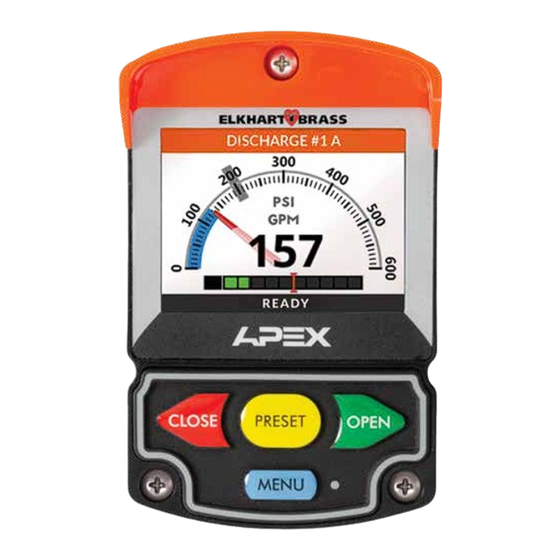
Controls and Indicators The display and pushbuttons controls are accessible on the front of the unit . (Refer to Figure 1 .) Valve Position Indicator When the valve is fully closed the red closed indicator will be on . The bar graph indicates the valve position as it moves from closed to fully open . -
Page 8: Installation
Installation The APEX valve controller is compatible with valves used with 1 .5 to 8 inch piping . NOTE: Plumbing systems are always unique and may cause small deviations in the factory calibration . If necessary a calibration procedure can be performed after installation . -
Page 9: Figure 2. Valve Controller Mounting Dimensions
Figure 2. Valve Controller Mounting Dimensions Recommended Panel Cutout incorrectly . NOTE: Page must be printed at 100% or template size will be scaled 3 1/16" R 1/2" 2 1/2" 4 7/8" 4 9/16" 2 3/8" #10 clear (thru-bolt with nut) 2 7/8"... -
Page 10: Install Pressure Sensor (Apex 200 And 300)
Install Pressure Sensor (APEX 200 and 300) The pressure sensor is mounted on the downstream side of the discharge valve . Pressure sensors are interchangeable . It is recommended that the calibration be checked if pressure sensors are swapped . Note: Install the pressure sensor upright so water in the end of the sensor is able to drain back into the pipe . -
Page 11: Figure 3. Pressure Sensor
Figure 3. Pressure Sensor 600 PSI DISCHARGE SENSOR For use with the Electric Valve Controller Elkhart Brass Elkhart, P/N: 65106000 RANGE: 0 - 600 PSIG OUTPUT: 0.5 - 4.75 VDC 800.346.0205 SER. NO: #### ####### EXCIT: 5 VDC U.S. PATENT: #,###,###... -
Page 12: Install Flow Sensor (Apex 300)
Install Flow Sensor (APEX 300) There are several ways to install Elkhart Brass paddlewheel type flow sensors . Mounting options include saddle clamps, weldments, and special valve adapters . Each mount will meet particular plumbing requirements . Flow sensors are interchangeable . It is recommended that the calibration be checked if flow sensors are swapped . -
Page 13: Figure 4. Flow Sensor Location Guide
Figure 4. Flow Sensor Location Guide The preferred location for the mounting of a flow sensor is on the top half of the pipe . The best orientation is vertical . If the sensor is mounted on the bottom of the pipe, it may be susceptible to the accumulation of dirt . - Page 14 Saddle Clamp Installation Note: Ensure that the mounting location meets the requirements for uniform water flow . (Refer to Flow Sensor Location .) Note: Ensure that there is enough room for the saddle clamp, sensor, and connector to fit . (Refer to Figure 5 .) 1 .
-
Page 15: Figure 5. Saddle Clamp Installation
Figure 5. Saddle Clamp Installation RETAINER Note: When the retainer cap is tightened make sure the sensor rim flat spot does not disengage from O-RING the alignment tab and allow the flow sensor to rotate . PADDLEWHEEL FLOW SENSOR Note: Allow a minimum of 2 inches clearance at the sensor top ALIGNMENT for removal/installation of the... - Page 16 Weldment Installation Note: Ensure that the mounting location meets the requirements for uniform water flow . (Refer to Flow Sensor Location .) Note: Ensure that there is enough room for the weldment, sensor, and connector to fit . (Refer to Figure 6 .) 1 .
-
Page 17: Figure 6. Weldment Installation
Figure 6. Weldment Installation Pipe Size Dimension (Sch 40) 1.95 to 1.80 RETAINER 1.95 to 1.80 1.90 to 1.75 O-RING 1.88 to 1.73 1.88 to 1.73 PADDLEWHEEL 1.85 to 1.70 FLOW SENSOR Measurements are in inches. TRU-SEAL Make sure that the alignment tab is LOCKNUT centered on the pipe centerline . -
Page 18: Electrical Connections
Electrical Connections Figure 7. Control Module Wiring USB ACCESS PORT* 6-PIN CONNECTOR PIN 1 VENT Valve Controller 6-Pin Connector *NOTE: If opened, USB access port Signal Description plug must be tightened to a torque Power 12/24 VDC of 8-10 in-lbs . Exceeding this torque value can result in damage Pressure Sensor Ground to its water seal capability . -
Page 19: Figure 8. Valve Actuator Wiring
Figure 8. Valve Actuator Wiring 6-PIN CONNECTOR PIN 1 12-PIN CONNECTOR PIN 1 Actuator 6-Pin Connector Actuator 12-Pin Connector Signal Description Signal Description Pressure Sensor 5 VDC Power 12/24 VDC Pressure Sensor Ground Ground Pressure Sensor Signal Valve Position 5 VDC Flow Sensor 5 VDC Valve Position Ground Flow Sensor Ground... -
Page 20: Figure 9 . Wiring (Cables And Connectors)
Figure 9. Wiring Butt Splice Connectors 6-Pin Plug +12 VDC Connector Black To APEX Valve Controller Display Terminating Resistor 3-Pin Receptacle Connector Harness A–APEX Harness with Terminating Resistor (Included with APEX Controller) P/N 37542000 2-Pin Connector Butt Splice Connectors 12-Pin Plug +12 VDC Connector Black... -
Page 21: Figure 10 . Wiring (Cables And Connectors)
Figure 10. Wiring Connectors 3-Pin Plug Connector Harness D–CAN Harness without Terminating Resistor (Included with Each Controller and E14X/16X Actuator) P/N 375440NT 3-Pin Plug 3-Pin Plug Connector Connector Harness E–CAN Extension Harness (Optional) P/N 37543002 - 2' P/N 37543010 - 10' P/N 37543015 - 15' P/N 37543020 - 20' P/N 37543030 - 30'... -
Page 22: Figure 11 . Apex 1:1 Wiring Connections
Figure 11. APEX 1:1 Harness Connections... -
Page 23: Figure 12 . Apex 2:1 Wiring Connections
Figure 12. APEX 2:1 Harness Connections... -
Page 24: Initial Setup Adjustments
Initial Setup Adjustments After the hardware has been installed, the valve controller and actuator must be properly setup . To adjust settings or change parameters use the menu functions . The Menu is accessed by pressing and holding the MENU button . Valve Position Calibration NOTE: If using an EB_J or EB_S butterfly valve refer to ”Valve Polarity“... - Page 25 Valve Controller Name Configuration The valve controller can be set to display a custom name to identify the discharge it is used with . This name can be selected from a predefined list or a custom name can be created . This name will be displayed in the Header bar in the Operator screen .
- Page 26 Importing Custom Name List: A custom name list can be imported from a USB device into the unit . The imported list will replace the default list . 1 . Create a plain text file on a computer and save this file as ”namelist .txt“ . (This file name must be in all lowercase letters and the file extension should end with "...
- Page 27 Units of Measure (UOM) The valve controller can be set to display information in Imperial or Metric units of measure . Several configurations of these units are available to choose to suit the operator’s preference . 1 . Select USER SETTINGS on the menu screen . Press PRESET button until the user setting is selected .
- Page 28 3 . To adjust the marker position, select the TARGET PRESSURE item by pressing the OPEN button . 4 . The display will show the current Target Pressure value selected . To change this value, use the OPEN button to increase, and the CLOSE button to decrease the value .
-
Page 29: Display
Display Display Brightness The APEX unit will automatically switch the screen appearance and brightness level to match ambient light . Brighter color scheme and higher brightness intensity is used for daylight . Darker color scheme and lower intensity is used for nighttime . Screen brightness can be adjusted individually for daytime and nighttime . - Page 30 To change these settings: 1 . Select DISPLAY item on main menu screen . Press the OPEN button to access this menu . 2 . Select DAY/NIGHT MODE item in the Display menu . Press the OPEN button to access this menu . 3 .
-
Page 31: User Settings
User Settings Adjusting User Settings Reset Water Total APEX controllers that have a water flow sensor will accumulate total water volume discharged when the valve is open . This number is recorded in an event log each time after the valve is fully closed . -
Page 32: Operation
Operation On power-up the valve control will be in the normal operating mode . The green OPEN, red CLOSE, and yellow PRESET buttons will control valve position . The yellow PRESET button will set the valve to a programmed position . The blue MENU button switches to the Menu Screen . (Menu Screen is activated when this button is pressed and held down for two seconds.) Information from the pressure and flow sensors is processed and displayed (only for the APEX200/300 models) . - Page 33 Button Operations Green OPEN button: Press and hold to move the valve in the Open direction . Valve will stop when the button is released, or when it is fully open . Red CLOSE button: Press and hold to move the valve in the Closed direction . Valve will stop when the button is released, or when it is fully closed .
- Page 34 Menu Screen Layout of Components A—Header Bar: Current Menu/Sub menu title and icon are displayed . B—Content Area: Displayed as a list of menu items/options . Each menu item is shown with a title, icon to the left and the current value (or status) . Position bar on the right side of the display screen shows the position of the selected menu item .
- Page 35 Button Functioning in Menu Screens While navigating through any of the menu screens, the keypad buttons (below the LCD display) are used to navigate, select menu items, adjust values, save and cancel changes/ menu selections . Typical Button Functions: CLOSE button (Red) •...
- Page 36 PRESSURE SCALE: Menu Functions Outline FULL RANGE DISPLAY NARROW RANGE DISPLAY BRIGHTNESS: TARGET PRESSURE (Adjust #): Brightness Day Brightness Night SETUP DAY/NIGHT MODE: Auto Local UNIT ID: Auto Remote PAIR VALVE: Auto Master VALVE POLARITY: Day Only Normal- Type T1 Night Only Reverse- Type T2 D/N THRESHOLD (Adjust #):...
- Page 37 MAINTENANCE VALVE CALIBRATION FLOW CALIBRATION: PRESS . CALIBRATION: DIAGNOSTICS IDENTIFY: DIAG . SCREEN: FIRMWARE REV .: HARDWARE: RESTART UNIT: ACCESS ENTER CODE (Adjust #): LOGOUT: FACTORY DEMO MODE: PRODUCT: MODEL: APEX100 APEX200 APEX300 FIRMWARE UPDATE: Update Remote Device FACTORY RESET:...
-
Page 38: Event Log
Event Log Event Log Functions The valve controller is equipped with log feature, which records events during operation . Recorded events are: • Total Water Volume Accumulated–Recorded each time the valve is fully closed . • Parameter Change–Recorded when settings/parameters have been changed . •... - Page 39 Setting the Log Files Limit Log files limit determines how many log files are saved into the internal memory . When the number of the files exceeds this limit, the oldest files are deleted . 1 . Select ‘EVENT LOG’ on the main menu . Press the OPEN button to access the submenu . 2 .
-
Page 40: Setup
Setup User Access Level To prevent unintentional parameter changes, a number of settings are only available to users with advanced access permissions . In order to gain access to these settings, an operator needs to enter their access code . NOTE: the shield icon indicates that this parameter requires an advanced user access level . - Page 41 Valve Polarity (Must be done for EB_J & EB_S Butterfly Valves.) Valve Polarity setting allows the valve direction of travel to be changed . If the valve opens when the CLOSE button is pressed, or closes when the OPEN button is pressed, then the valve polarity setting must be changed .
- Page 42 CAN Message Rate Valve data is updated (refreshed) at a preset time interval . It is recommended to leave this setting at the indicated default . However, this interval can be adjusted if required . 1 . Select SETUP in the menu screen by pressing the PRESET button . Press the OPEN button to access this menu .
- Page 43 2 . The current file name will be highlighted for editing with the cursor blinking . Use the OPEN button to change to the next character at the cursor position . Use CLOSE button to select the previous character in the cursor position .
-
Page 44: Factory Settings
APEX valve controllers have different feature sets, depending on the sensors connected to the valve . • APEX 100 model has a display with valve position only . • APEX 200 model has valve position and pressure display . • APEX 300 model has valve position, pressure display and water flow rate . - Page 45 Factory Reset This function restores the unit to factory settings . Performing a factory reset will erase all settings, except for the valve controller model . All system logs will be deleted . The setup process will need to be repeated . 1 .
- Page 46 Firmware Update The firmware running on the valve controller can be updated if necessary . The updates will be provided by the manufacturer . The firmware update files will be saved on a USB device . 1 . On the back of the unit, remove the USB access port cap located next to the wiring connector .
- Page 47 NOTE: The update process might take several minutes . Unit will restart several times, and the screen might be blank . Allow the process to continue uninterrupted; DO NOT DISCONNECT POWER! 7 . When the firmware update has successfully been completed, the confirmation dialog box will appear .
-
Page 48: Maintenance/Calibration
Maintenance/Calibration Water Flow Rate Calibration (APEX 300) For APEX models 300, a water flow sensor reading needs to be calibrated against an external flowmeter . Before the process begins, connect an external flowmeter to the discharge controlled by the valve under calibration . Ensure the water pump is running . Water Flow Rate Calibration 1 . -
Page 49: Pressure Calibration
Pressure Calibration Pressure calibration is not typically required; the unit is normally factory calibrated . If the pressure reading is substantially different that the actual pressure, please confirm that the sensor is not defective . In the event the pressure reading is off by a small amount, the unit can be recalibrated . Before the process begins, connect an external pressure meter to the discharge controlled by the valve under calibration . - Page 50 10 . When the pressure has been entered, press the PRESET button until ’ADD CALIBRATION POINT‘ has been selected . Press the OPEN button to add this data as a calibration point . Confirmation dialog box will appear to indicate this operation was successful . 11 .
-
Page 51: Diagnostics
Diagnostics Diagnostics Tools To assist with troubleshooting and setup, a number of diagnostic tools are available within the valve controller . Diagnostics Screen Utility When activated, operator screen will be replaced with the diagnostics screen, which provides detailed information on the valve controller and the CAN network parameters . 1 . - Page 52 Firmware Revision Information To determine the current software revisions, follow the steps below . 1 . Select ‘DIAGNOSTICS’ item in the main menu . Press the OPEN button to access this menu . 2 . Select ‘FIRMWARE REV .’ item . Press the OPEN button to display this submenu . The list of current revisions will be displayed: •...
-
Page 53: Active Error/Warning
Active Error/Warning All active error/warning codes can be reviewed when needed through the menu system . Accessing Active Error/Warning List 1 . Select ‘ACTIVE WARN ./ERR .’ from the main menu . Press the OPEN button to access the submenu . 2 . -
Page 54: Error/Warning Codes Troubleshooting Table
Error/Warning Codes Troubleshooting Table The table is provided to assist in tracking down system problems, it is not meant to take the place of good troubleshooting practices . Table 2. Error/ Warnings Codes and Troubleshooting Code Message Description Probable Cause Corrective Actions E0001 NO DATA... - Page 55 (Continued Table 1 . Error/ Warnings Codes and Troubleshooting) Code Message Description Probable Cause Corrective Actions E0205 PRESS . SENSOR FAIL Pressure sensor signal outside of Check if sensor is installed and range . plugged in . Pressure sensor is unplugged or Check pressure sensor .
- Page 56 NOTES...
- Page 58 NOTES...
- Page 60 Elkhart Brass Manufacturing Co ., Inc . 1302 W . Beardsley Avenue Elkhart, IN 46514 Tel . (574) 295-8330 Toll Free (800) 346-0250 Fax (574) 293-9914 5-20 www .elkhartbrass .com © Elkhart Brass Mfg . Co ., Inc . 2019 Email: eb .info@safefleet .net 98600000 REV-A...
Need help?
Do you have a question about the APEX 100 and is the answer not in the manual?
Questions and answers