
Related Manuals for Supore ALE-1200


Summary of Contents for Supore ALE-1200
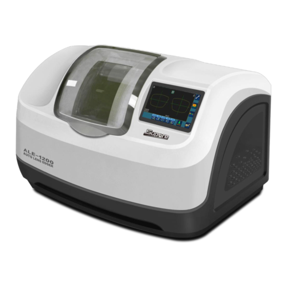
- Page 1 AUTO LENS EDGER ALE-1200 Operation Manual(V2.0) Shanghai Supore Instruments Co.,LTD. http://www.supore.com REV.20190125...
- Page 2 Dear respected user: Thank you for choosing our product and trusting our company. ALE-1200 patternless lens edger is developed specially for optical shops to edge the lens. Please read the manual carefully and put it near the edger for easy reference.
- Page 3 DESCRIPTION OF SYMBOLS Different symbols in manual can draw attention of users and can distinguish different matters.(e.g. matters related to safety) Following diagram have lists all symbols and descriptions: Symbol Description Important warning, marking the meaning is: if the violation, inappropriate operation of the machine, and the risk of serious damage to the existence of life.
-
Page 4: Table Of Contents
CONTENT Preface ................................. - 1 - 1. ASSEMBLING ............................- 5 - 1.1 Open the packaging of machine ....................- 6 - 1.1.1 Warning ..........................- 6 - 1.1.2 Procedure ........................... - 6 - open the package in the following steps:: ................- 6 - 1.2 Take away the fixing rail wHich is used during transportation ............ - Page 5 5.5 CLEAN/REPLACE WATER-PROOF COVER ..................- 36 - 5.6 CLEAN THE FILTER AND WATER TANK ..................- 37 - 6.TECHNICAL SPECIFICATIONS ......................- 38 - 6.1 FEATURES ............................. - 38 - 6.2 TECHNICAL PARAMETERS ......................- 39 - 7.ATTACHMENT LIST (PACKING PARTS) ..................... - 40 - - 4 -...
-
Page 6: Assembling
1. ASSEMBLING # 2. #5 Please keep the packaging materials - 5 -... -
Page 7: Open The Packaging Of Machine
1.1 Open the packaging of machine 1.1.1 W ARNING > The machine must be placed in the direction of the package logo, can not be inverted. > Put the machine on a flat, stable surface. 1.1.2 P ROCEDURE :: OPEN THE PACKAGE IN THE FOLLOWING STEPS #1 Need at least two people to put the machine on the ground;... -
Page 8: Open The Package In The Following Steps
1.2 TAKE AWAY THE FIXING RAIL WHICH IS USED DURING TRANSPORTATION 1.2.1 C ONDITION > Put the machine on the workbench > need enough space around the machine. 1.2.2 P ROCEDURE Open the package in the following steps #1 With the help of another person, gently flip the machine in order to gain access to the 4 fixing screws of the carriage;... -
Page 9: Prepare The Working Table
1.3 PREPARE THE WORKING TABLE 1.3.1 M ACHINE SPECIFICATION The machine specifications is as shown below:: 442mm 705mm 465mm > length = 705mm > height = 442mm > width = 465mm >Total Weight = 65kg - 8 -... -
Page 10: Working Table Size And Drilling Hole Requirement
1.3.2 W ORKING TABLE SIZE AND DRILLING HOLE REQUIREMENT The figure below shows the location of the edger on the workbench and where drilling is required. Place the machine well before drilling to determine the position! 356mm 190mm 465mm width: 100mm diameter of the drainage:... -
Page 11: Water Supplying System
1.4 WATER SUPPLYING SYSTEM 1.4.1 D ESCRIPTION 1.4.1.1 O VERVIEW >The machine must be installed with a water shut-off valve, its position can not be 80cm higher than the machine. Stop valve position must be easy to operate, so that the machine can be closed in any time when we don't use it. - Page 12 1.4.2.2 PROCEDURE As is showed in the picture: outlet of the pump amount water exceed the pump water level connect the water pump or the electromagnetic valve Connect the solenoid valve Connect the water pump to use to supply water directly recycled water 在...
- Page 13 Follow the steps below to connect the water supply pipe to the edger and fix it. #1 Check if the machine switch is disconnected,ON / OFF switch in the OFF position,the main power plug is disconnected. #2 Check the water supply system is closed. #3 Make sure the machine level =>...
-
Page 14: Electrical Connection
1.5 ELECTRICAL CONNECTION 1.5.1 E LECTRICAL WIRE OF EDGER >Power outlet must be connected with earth wire,When installing, please make sure the whole shell is connected with earth wire. The whole shell is connected with earth wire #1 Check if the machine switch is off: The ON / OFF switch is in the OFF position and the main power plug is off #2 Connect the scanner to the RS232 port. -
Page 15: Start The Edger
1.6 START THE EDGER 1.6.1 P ROCEDURE Start the machine according to the following procedure: #1 Check if the machine switch is off: The ON / OFF switch is in the OFF position and the main power plug is disconnected. #2 Install the collet and collet seat onto the spindle. -
Page 16: Safety Precautions
2. SAFETY PRECAUTIONS 2.1 NOTICE 2.1.1 O PERATOR > Read the instructions carefully and keep it near the machine for easy reference. > The machine has a rotating device,the wheel has potential danger.don't put your hand near the grinding wheel. The machine is heavy, need at least 2 people to carry. >... -
Page 17: Suggestions
2.2 SUGGESTIONS > Observe the equipment maintenance requirements. > Place the power cord properly. > All maintenance matters, please contact the seller and professional technical personnel, must use the appropriate accessories. > Only can be connected online with the device specified by the seller. >... -
Page 18: Use Of Edger
3.1.1.1 TOUCH SCREEN > functions of the touch screen: >> operate the interface of ALE-1200 >> Input the data of the processing tasks >> Display the shape of the frame and lens >> Input the data of the edger 3.1.1.2... -
Page 19: Introduction Of The Operate Interface
3.2 INTRODUCTION OF THE OPERATE INTERFACE 3.2.1 D ISPLAY INTERFACE >>Menu interface; >>Enter the data change shape interface,can change the shape of the lens; >>Symmetrical display of the data for both left and right eyes >>Enter the interface of lens processing ; >>Get the current required processing data and display;... -
Page 20: Screen 1:1Display
3.2.2 S : CREEN DISPLAY >click in the screen,enter frame 1:1 display surface. >click in the screen,back to the,back to Main interface. >>DBL:nose bridge distance of the frame; >>PD: Pupil distance of two eyes; >>FPD:Geometric center distance of frames; >>Dia:The minimum lens diameter required to processing the current lens; >>A:... -
Page 21: Modify Of Pattern Data
3.2.3 M ODIFY OF PATTERN DATA >click on the main interface,enter the interface that the data change the shape. >>Retrieve existing template data from memory; >>Find the template data in memory; >>Save the current template data to memory; >>Template height unchanged, width modified; >>Template width unchanged, height modified;... - Page 22 3.2.3.1 STORAGE OF THE TEMPLATE DATA >click on the interface,The system pops up a save window, enter the template number coding, as is shown below. >Click the "Enter" button on the numeric keypad, the system automatically saves the current template data. 3.2.3.2 T EMPLATE DATA SEARCH >click...
-
Page 23: Pick Up Stored Data
3.2.4 P ICK UP STORED DATA >click on the shape change interface,enter the template data retrieval interface, the memory data list will be showed >>Display previous page data; >>Display next page data; >>Display the previous data; >>Display the next data; >>Retrieve the current data;... -
Page 24: Edging Lens Interface
3.2.5 E DGING LENS INTERFACE >click the on the main interface, Into the lens processing settings interface. 1.Left and right eye processing options: >>right eye >>left eye 2.Lens material options: >>Resin lens >>PC >>TRIVEX >>glass >>HR 3.Edge shape options: >>Bevel edge >>Flat edge 4.Sharp edge rate:... -
Page 25: Lens Processing
>> backside safe chamfering(middle) >> backside safe chamfering(large) 8.Lens processing mode: >>Optical Center mode >>Geometric center mode 9.Polishing choice: >>polish >>not polish 10.Others: >>unlock the lens >>start to proceeding >>stop proceeding >>proceeding size >> retouch 11.Clamping pressure: >>(level one)Fragile lens >>(level two)normal lens >>(level three)slippery lens >>return... -
Page 26: Start/Stop The Grinding Procedure
Warning: please install 19mm small clamp > Remove the lens from the grinding window Open the water-proof cover after the machine stops or breaks. Press ,the clip shaft opens automatically. Remove the processed lens,but do not remove the block so you can re-grind it if necessary. 3.3.2 S TART STOP THE GRINDING PROCEDURE... - Page 27 #7 Select lens processing mode; #8 Select clip pressure; #9 After blocking, put the lens in and clamp; #10 Start; #11 Open the window, remove the shaft and take the lens after it’s done. : MPORTANT NOTE > Automatic bevel The tip vertex position is automatically located 1/3 of the front of the lens.
- Page 28 > Half - frame or rimless lens processing #1 Download template processing data; #2 Select lens for left eye or right eye; #3 Select lens material; #4 Select lens fine grinding pattern(flat); #5 Select polish or not; #6 Select lens processing mode ;...
-
Page 29: Processing Range
3.3.4 P ROCESSING RANGE > Lens Diameter:Unprocessed lenses, with a diameter of 80mm and 10mm offset, that is to say, the maximum diameter of 100mm without offset lenses. Thickness: maximum thickness of resin lens:18mm maximum thickness of glass lenses:16mm Lens minimum center thickness:1.2mm Completed rough lens, the maximum thickness of the flat side:11mm Completed rough lens, the maximum thickness of the edge of the glass:15mm Completed rough lens, the maximum thickness of the resin tip:15mm... -
Page 30: Configuration Menu
4.CONFIGURATION MENU 4.1 CONFIGURATION MENU INTRODUCTION 4.1.1 S YSTEM MENU INTERFACE >Click the icon on the main interface,Enter menu password,Enter the menu. >>The whole machine test; >>The machine set; >>Initial settings; >>Processing statistics table; - 29 -... -
Page 31: The Test Menu
4.1.2 T HE TEST MENU >Click the key on the main interface,Enter the machine test menu. >>The performance test of the machine head lift motor and encoder; >>Machine head horizontal moving motor, encoder performance test; >>Performance test of lens rotary motor and encoder; >>Scan probe component performance test;... -
Page 32: Setting Menu
4.1.3 S ETTING MENU >Click the key on the main interface,Enter the machine setting menu。 >>Clamp pressure correction; >>Grinding wheel position correction; >>Scanning probe correction; >>Processing size setting; >>Processing winding number setting; >>Base axis setting. (only apply to edger with grooving and safe chamfering Grooving setting >>... -
Page 33: Initial Parameter Setting
Otherwise, improper operation may affect the performance of machine processing. 4.1.4 I NITIAL PARAMETER SETTING >Click the key on the main interface,Enter the initial setup menu。 >After setting, click ,Save the initial setting parameters. 4.1.5 P ROCESSING STATISTICS TABLE >Click the key on the main interface,View the processing statistics. -
Page 34: Daily Maintenance Of Machinery
5.DAILY MAINTENANCE OF MACHINERY 5.1 MAINTENANCE INSTRUCTIONS To ensure that your edger is at its best, you must perform several maintenance operations to achieve the desired results within a range. > Clean touch screen > Maintenance of edger >> Use water spray bottle to clean the edger >>... -
Page 35: Replace Removable Clamps
5.3 REPLACE REMOVABLE CLAMPS Note: the lens holder is serrated and the lens probe is sharp. When touching the head and probe, make sure your hands are protected. 19 mm diameter adaptors 25 mm diameter adaptors 5.3.1 R EPLACE THE RIGHT CLAMP RUBBER PAD Replace the rubber pad procedure as below:... -
Page 36: Replace Lens Feeler
5.4 REPLACE LENS FEELER > Check the lens scanner regularly,change the it once the wear or damage is found(Or replace every 3,000 lenses). Dismountable lens feeler Remove the screws and replace the lens feeler >After the lens feeler is replaced, the lens feeler position needs to be recalibrated. The calibration probe procedure is as follows:... -
Page 37: Clean/Replace Water-Proof Cover
5.5 CLEAN/REPLACE WATER-PROOF COVER > Before starting any operation, you must ensure that the machine switch is Off: the On/Off switch is in the Off position and the main power is disconnected. The replacement procedure is as follows: : > Regular cleaning of the cover plate can clearly see the grinding edge chamber and the processing process;... -
Page 38: Clean The Filter And Water Tank
5.6 CLEAN THE FILTER AND WATER TANK > Before starting any operation, you must ensure that the machine switch is Off: the On/Off switch is in the Off position and the main power is disconnected. > Regular cleaning can ignore the number of lenses to be processed, but the manufacturer's recommendation is to clean about 100 pieces of lens (glass and plastic) per process. -
Page 39: Technical Specifications
6.TECHNICAL SPECIFICATIONS 6.1 FEATURES > Automatic initialization > Three - dimensional probe front & rear surface camber > wheel configuration: >> Glass grinding wheel >> Resin rough wheel >> Bevel/flat edge grinding wheel >> Bevel/flat edge polishing wheel > Automatic clip, three selections of clip pressure, adapt to different material lens processing >... -
Page 40: Technical Parameters
6.2 TECHNICAL PARAMETERS > The design standard is for indoor use > Dimension specification >> Length:705mm >> Width:465mm >> Height:442mm > Weight:65kg > Input Voltage:220V-230V/50Hz,110V-115V/60Hz > Machine power:1500W > Noise:72db > Operating Temperature:5℃~40℃ > relative humidity:10% - 80% > Pump working voltage:220V-230V /50Hz,110V-115V /60 Hz >... -
Page 41: Attachment List (Packing Parts)
7.ATTACHMENT LIST (PACKING PARTS) PART NAME QUANTITY Block pliers Butterfly head correction tool Scan probe 25mm clamp 19mm clamp 25mm clamp rubber mat 19mmclamp rubber mat Large block Middle block Sticker Power line Fuse (220V-15A or 110V-25A) Certificate of conformity Warranty card Operation menu Drier...
Need help?
Do you have a question about the ALE-1200 and is the answer not in the manual?
Questions and answers