Advertisement
Quick Links
MFD Crosshair automatic landing
www.MyFlyDream.com
V1.2
Performing an automatic landing requires a perfectly tuned plane.
Please make sure your plane follows routes perfectly before you try to
land it automatically. "Cross-track error" is very important during the
landing procedure. About "Cross-track error" please refer to appendix A
of this document.
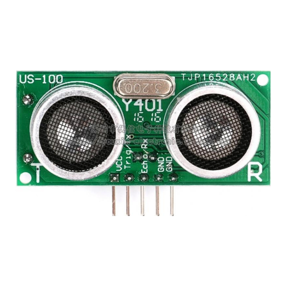
The above photo is the sonar used for auto landing. The "Trig/TX" pin
connects toD11 pin of the AP. The "Echo/RX" pin connects to D10 pin of
the flight controller. You also need to provide+5V power to the sonar.
We recommend to use the CAN-BUS connector of the harness included
Advertisement

Related Manuals for MyFlyDream Crosshair

Summary of Contents for MyFlyDream Crosshair
- Page 1 MFD Crosshair automatic landing www.MyFlyDream.com V1.2 Performing an automatic landing requires a perfectly tuned plane. Please make sure your plane follows routes perfectly before you try to land it automatically. "Cross-track error" is very important during the landing procedure. About "Cross-track error" please refer to appendix A of this document.
- Page 2 it AP kit to connect with the sonar. In this case you need to temporary discard the CAN-BUS function. Take the yellow and white wires out from the 24pin connector (Port D).Insert the yellow wire of the black CAN-BUS connector into D10, insert the white one into D11.
- Page 3 Please test it several times to ensure it works perfectly. The above picture shows a Laser Range Finder connected to a MFD Crosshair AP. To activate the Laser Range Finder please set menu [SENSORS SETTINGS->2ND ALTIMETER] = "LASER" instead of "SONAR".
- Page 4 This Laser Ranger Finder which is capable to measure 20meters is highly recommended for a more precise and reliable accuracy of auto-landing. You may find it particularly useful if you need to land somewhere remote. In this case you will probably want to utilize the Laser with our "Runway Scan"...
- Page 5 L1 is the location for final touchdown. Place the plane at this point and make sure that 12 or more satellites are locked by AP. Select the menu [L1 - SET] to let the AP record theL1 position. (Alternatively, you...
- Page 6 may enter L1 coordinates via your ground station software in case you are planning a flight to a remote location; more about that later). TheL1 coordinates(longitude/latitude)will be displayed at the bottom of the screen. L2 is the runway entry point. Following the above steps, record the L2 position.L2 altitude can be defined by the menu [L2 - ALT] in cm.
- Page 7 Auto Landing Procedure The above figure is a flight path of an automatic landing. In this example we selected[AUTO LANDING->RUNWAY1/2/3 ->TURN LEFT/RIGHT=LEFT], so the plane will circle on the right side of the runway before approaching. If you set [AUTO LANDING->RUNWAY1/2/3 TURN LEFT/RIGHT =RIGHT], the plane will use the left side of the runway.
- Page 8 If there is an active runway set and available, the flight mode on the upper left of the OSD screen will change to "LND 1"and the first stage of the landing procedure will be executed. The plane will fly towardL4 . When the distance from theL4 is close to the standard circle radius(defined by [AUTOPILOT SETTINGS->CIRCLE RADIUS]), the plane will turn right, flying into the tangent of the circle and begin to circle...
- Page 9 or reverse the thrust if the sonar altitude is less than the [BRAK ALT].During the brake period, the E9 port of AP outputs a 1800us PWM signal. After the plane stops or braking time (4 seconds)is up it restores to 1000us. The menu item[AUTO LANDING->...
- Page 10 plane will mistakenly think that there is still enough altitude below, and continue to land and hit the ground unexpectedly. The barometric altimeter relies on the recorded air-pressure of the takeoff point. After a long flight ( > 30 minutes, or even several hours), the air pressure at takeoff will likely change.
- Page 11 runway, and will calibrate the barometer for automatic landing. In this example, we define the maximum times of scans to be 2, but it can be up to 9 if you need. The following is a detailed description of runway scanning: 1.
- Page 12 brought in the GPS error. Nevertheless, as the GPS altitude error is usually less than 10 meters, it is safe to apply it on a 30m or a higher altitude of L4 / L3. 3. The plane maintains an (initial) SCAN RUNWAY ALT (25 meters in this example) and flies over the runway.
- Page 13 considered valid for a short time, and accurate enough to perform the automatic landing safely. 4. If the plane flies too high above the point L1 and cannot get a laser altitude reading (usually it should be less than 25 meters to obtain an valid laser altitude, the scanning distance will increase in a dark environment), the plane will circle around L4 again, and then perform the next runway scanning at a 5 meters lower then previous altitude.
- Page 14 high (for example, 40 meters), we usually recommend to increase the maximum number of scans simultaneously (for example, to 6 – to ensure that the plane can detect the runway before all scan takes are used up). If the plane fails to detect the runway after the set number of scans, it will use the GPS-calibrated altitude value to perform the landing procedure.
- Page 15 In the screenshot, LND1SCN1@23m indicates that the plane is trying the first scan, Stage 1 (circling around L4), and the attempted altitude is 23 meters (relative to the runway) It can be seen in this screenshot that after 200 KM of flight, we need to use the scan result of the laser altimeter to correct the barometric...
- Page 16 AltitudeTrim altimeter, and the =-39.9 meters. The objective barometric altitude of the plane in the screenshot is -6 meters. In fact, after landing we can see the ground barometric altitude reading was -38 meters, so this circling altitude is actually about 32 meters from the ground, which is safe.
- Page 17 it, which is good enough. But during Landing we also need to control the distance between the plane and the line that we should follow. This distance between the plane and the route line we call the "Cross-track error". Before tuning Cross-track-relative settings please make sure your plane flies quite straight in STB mode and accurately flies toward the target in WPT mode.
- Page 18 Set 2 or more waypoints with 1km spacing and fly the plane in WPT mode. Observe the behavior of the plane. Green=Perfect, Red=P is too High, Brown=P is too Low We use P/I/D parameters to control the cross-track performance. Use [AUTOPILOT SETTINGS->CROSS-TRACK-P/I/D]to tune up the plane till you get the best Cross-track performance.
- Page 19 You can also adjust the parameters when the plane is in the air by a pair of data-radios and mission planner software. About PID tuning: P(Proportion) is the most important parameter out of the three. A too high P value will cause short-term period oscillation. The plane will frisk from left to right frequently.
- Page 20 However, you can also use Mission Planner to define a runway even if you have never been there. Mission Planner software can be used to get this job done (we hope to modify MFD GCS to do that soon, too).Please note that we are using mission planner in a particular way to upload / download the runways here, you have to pay attention to read the following information.
- Page 21 1. You have 2, and only 2 WayPoints (in mission planner they call it "missions").Trying to override this limit will trigger alarm messages on OSD and fail to upload. 2. Choose "LAND" in the "Command" column for these 2 points. 3.
- Page 22 4.Upload this mission to AP with above settings. The AP will recognize this as a runway. The corresponding runway (1 in this example) will be updated. 5. L3 or L4 will be generated by the AP after you upload the runway. You can also use the OSD menu to adjust the L3 altitude or any other parameters after uploading.
- Page 23 L3 and L4 are generated by the AP. Usually you can only imagine where they are. But with the above skill you can visually check where exactly they are on the map. In the above screenshot you can also see the ASL altitude of L1/L2/L3/L4 (36/37/69/69 meters).
Need help?
Do you have a question about the Crosshair and is the answer not in the manual?
Questions and answers