
Subscribe to Our Youtube Channel
Related Manuals for Synel SYnergy/A

Summary of Contents for Synel SYnergy/A
- Page 1 Synel Americas 480-37 4-7700 8665 E. Hartford Dr. Suite 100 www.synel-americas.com Scottsdale, AZ. 85255 sales@synel-americas.com V Feb 2020...
-
Page 2: Product Manual
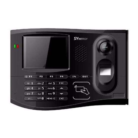
Pictures in this manual are for illustration purposes only. SYnergy/A is a trademark of Synel Industries Ltd. All trade names referenced herein are either trademarks or registered trademarks of their respective companies. - Page 3 Java graphics libraries SWT and SWING and TSL/SSL communication encryption. SYnergy/A is compact in size and attractively designed and is also equipped with a built in camera and a speaker for generating various sound effects such as alert notifications, report confirmation/rejection and other actions or events.
-
Page 4: Technical Specifications
2. Technical Specifications The following table displays the technical specifications for SYnergy/A Operating system Advanced Linux open source embedded OS High speed processor ARM 9 - 400 MHz Identification Unit Optical fingerprint (FP) sensor FP template size 1404 Byte (SmackBio) 785 Bytes (Suprema) Registered FP Capability 3,000 FP;... - Page 5 Multi-media Function Advertisement page broadcast, background music, Video files Keyboard 6 programmable function keys, 10 alphanumeric keys, menu key Back up battery RTC 3 years Back up battery for 120 minutes operation Coupon Printer Supported CE/TUV/FCC and ROHS Standards Approval 2.1 Additional Technical and Interface Specifications •...
- Page 6 Suprema FPU SFM5020 (optical sensor) Model SFM5020 Module format Shared Library File name fp.so Image dimension 272 pixel(W)x320 pixel(H) 500 dpi FP data size pre 1FP 768 Bytes Internal database capacity Up to 9,050 templates Speed Exact time <0.7 sec <0.1% Accuracy <0.0001%...
- Page 7 2.1.2 Physical characteristics Front view Depth 55mm 2.1.3 Power Requirements • External AC/DC switching adapter, DC 100-240/Volt -> 10Watt-12V/2A Back-up battery-rechargeable included POE-802.3af (Power Over Ethernet) Page 6 of 18...
- Page 8 2.1.4 Environment Temperature: 0 -50 Humidity: 10% -90% 2.1.5 Communication and configurations 2.1.5.1 Communication parameters Communication between the host and terminals is performed under an asynchronous mode. The baud rate is programmable, enabling rates from 9600 to 115000 bps. 2.1.5.2 Multiple terminal configuration RS-485 communication enables you to connect up to 32 terminals to a single COM port and/or to extend the cabling distance to up to 1,000 meters (3,280 feet) using 9600 baud via an RS-485 multi- drop line.
-
Page 9: Front Panel
3. Terminal This terminal is enclosed in a rugged plastic molded casing and is secured to the wall using four screws and a removable panel. 3.1 Front panel On the left side of unit, there are two programmable LED indicator lights with different colors. The functions can be defined by the user. - Page 10 3.2 Side USB socket The side of the terminal contains a connection socket for connecting a USB cable or device. Turn the socket cover to reveal the USB socket. 3.3 Bottom connection sockets The bottom of the terminal contains connection sockets for external connections. 1-GPI/O - PIN no.
- Page 11 4. Unpacking Check the box and contents for signs of damage that may have occurred during shipment. Do not throw away the box or any of the packing materials. The terminal package contains: Phillips flat head 4x50 mm screws & Terminal anchors (3 x brick/cement 3 x plaster walls)
-
Page 12: Installation
5. Installation 5.1 Selecting the Terminal Location General Considerations • The terminal should be placed near an easily accessible power outlet. • Make sure there is enough space around the terminal for the communication cabling. • Do not place the communication cable near a source of electromagnetic radiation or radio interference such as power lines, large machinery, etc. - Page 13 5.2 Terminal Wall Mounting Make sure the unit is not plugged into a power source. If you have already connected your terminal to a PC, disconnect it. You can reconnect it after you have completed mounting the unit. The terminal contains computer components. It should not be mounted where it will be exposed to extreme heat or cold, water, steam, violent vibrations, high electromagnetic radiation including high voltage power lines and electrical equipment.
-
Page 14: Communication Connections
Communication Connections Select a location for the connection box. The box must be positioned where both the communication line and the terminal can be connected to it. The terminal should be placed near the connection box, and must be within the reach of the short RJ45 cable. Plug the communication cable from the terminal into the connection box. -
Page 15: Terminal Maintenance
6. Maintenance This section gives instructions for maintaining the terminal in good working order. The issues described are: • Terminal Maintenance • Calibrating the Real Time Clock (RTC) • Formatting microSD card • Clear terminal Flash • Fingerprint sensor cleaning and care 6.1 Do’s and Don’ts •... - Page 16 6.2.2 Every six months General • Verify that all cables to the terminal ports are well connected. Keypad and screen • Keypad and screen: Turn off the device, and clean the keypad and screen with a rag or neutral detergent, then wipe dry.
- Page 17 • Caring for the Fingerprint Sensor Do not place the fingerprint sensor close to a heat source, such as a radiator or hot plate. Do not subject the fingerprint sensor to heavy shocks/ vibrations Do not allow the sensor to come in contact with metallic objects. •...
-
Page 18: Connectors And Jumpers
7. Connectors and Jumpers PC communication - RJ-45 (8 pin) with LED indicator Serial Communication with PC Yellow led is an indication for TXD of terminal Green led is an indication for RXD of terminal Printer - RJ- 11 (6 Pin) Signal Value Remarks... - Page 19 I/O- RJ- 11 (6 Pin) Signal Value Remarks Input Relay Relay Relay Synel Americas 8665 E. Hartford Dr. Suite 100, Scottsdale, Arizona 85255 Phone – 480.374.7700 Fax – 480.682.0935 Page 18 of 18...
Need help?
Do you have a question about the SYnergy/A and is the answer not in the manual?
Questions and answers