Table of Contents
Advertisement
Quick Links
Advertisement
Table of Contents
Troubleshooting

Related Manuals for Mindray DPM 6


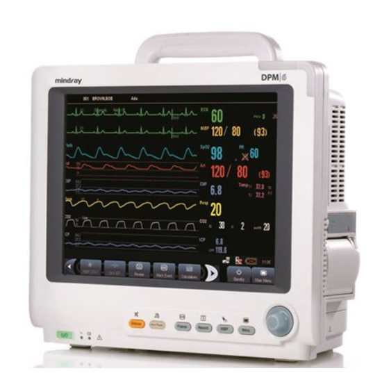
Summary of Contents for Mindray DPM 6
- Page 1 DPM 6 Patient Monitor Service Manual...
- Page 3 Mindray DS, nor the rights of others. Mindray DS does not assume any liability arising out of any infringements of patents or other rights of third parties.
- Page 4 FOR YOUR NOTES...
- Page 5 Preface Manual Purpose This manual provides detailed information about the assembling, dissembling, testing and troubleshooting of the equipment to support effective troubleshooting and repair. It is not intended to be a comprehensive, in-depth explanation of the product architecture or technical implementation.
- Page 6 Abbreviations Abbreviations used in this manual are: multi-parameter module satellite module rack central monitoring system Passwords A password may be required to access different modes within the monitor. The passwords are listed below: User maintenance: 888888 Factory maintenance: 332888 Demo mode: 2088...
-
Page 7: Table Of Contents
Contents 1 Safety ..........................1-1 1.1 Safety Information ......................1-1 1.1.1 DANGER ......................1-2 1.1.2 Warnings......................1-2 1.1.3 Cautions ......................1-2 1.1.4 Notes ........................1-3 1.2 Equipment Symbols ......................1-3 2 Theory of Operation ......................2-1 2.1 Introduction........................2-1 2.2 System Connections ......................2-2 2.2.1 Mounting the Patient Monitor ................ - Page 8 3.3 Power On Test ....................... 3-14 3.4 Module Performance Tests.................... 3-15 3.4.1 ECG Tests and Calibration ................3-15 3.4.2 Resp Performance Test..................3-16 3.4.3 SpO Test......................3-16 3.4.4 NIBP Tests......................3-16 3.4.5 Temp Test ......................3-17 3.4.6 IBP Tests......................3-17 3.4.7 C.O.
- Page 9 4.6.5 Button and Knob Failures .................. 4-7 4.6.6 Recorder Failures ....................4-7 4.6.7 Output Interface Failures..................4-8 4.6.8 CF Card Problems ....................4-8 4.6.9 Power Supply Failures ..................4-9 4.6.10 Network Related Problems................4-10 4.6.11 Software Upgrade Problems................4-11 4.6.12 Technical Alarm Messages................4-11 4.6.13 M51A Self Test Information................4-11 5 Repair and Disassembly ....................
- Page 10 6.6.4 RM Module ...................... 6-32 6.6.5 ICG Module ..................... 6-33 6.6.6 AG Module....................... 6-35 6.6.7 BIS Module ...................... 6-37 6.6.8 IBP Module ...................... 6-39 6.6.9 Mindray CO Module..................6-40 6.6.10 Oridion CO Module ..................6-42 6.6.11 CCO Module ....................6-43 6.7 Remote Display Box .....................
- Page 11 7.3 Upgrading Functional Assemblies .................. 7-5 7.3.1 Upgrading SMR ....................7-5 7.3.2 Upgrading Wireless Network Function.............. 7-5 7.3.3 Upgrading Recorder ................... 7-6 7.3.4 Upgrading Analog Output .................. 7-6 7.3.5 Upgrading CIS ....................7-6 7.4 Upgrading Software ......................7-7 7.4.1 How to Upgrade Software.................. 7-8 A Electrical Safety Inspection ...................
- Page 12 FOR YOUR NOTES...
-
Page 13: Safety
Safety 1.1 Safety Information DANGER Indicates an imminent hazard that, if not avoided, will result in death or serious injury. WARNING Indicates a potential hazard or unsafe practice that, if not avoided, could result in death or serious injury. CAUTION Indicates a potential hazard or unsafe practice that, if not avoided, could result in minor personal injury or product/property damage. -
Page 14: Danger
1.1.1 DANGER There are no dangers that refer to the product in general. Specific “Danger” statements may be given in the respective sections of this manual. 1.1.2 Warnings WARNING All installation operations, expansions, changes, modifications and repairs of this product are conducted by authorized personnel. There is high voltage inside the equipment. -
Page 15: Notes
1.1.4 Notes NOTE Refer to Operation Manual for detailed operation and other information. 1.2 Equipment Symbols Attention: Consult accompanying documents CIS connector (this manual). Danger: High-voltage Network connector Alternating current(AC) Defibrillator connector Connector for satellite Power ON/OFF module rack Battery indication Video output Zero key Auxiliary output connector... - Page 16 FOR YOUR NOTES...
-
Page 17: Theory Of Operation
Theory of Operation 2.1 Introduction This patient monitor is designed to monitor a fixed set of physiological parameters including ECG, heart rate (HR), respiration (Resp), temperature (Temp), SpO , pulse rate (PR), non-invasive blood pressure (NIBP), invasive blood pressure (IBP), cardiac output (C.O.), carbon dioxide (CO ), oxygen (O ), anesthetic gas (AG), impedance cardiograph (ICG),... -
Page 18: System Connections
2.2 System Connections 2.2.1 Mounting the Patient Monitor The patient monitor can be mounted on a wall bracket or on a trolley support. The wall bracket or trolley support can be ordered optionally. Each type of mounting bracket is delivered with a complete set of mounting hardware and instructions. Refer to the documentation delivered with the mounting hardware for instructions on assembling mounts. -
Page 19: Connectors For Peripheral Devices
2.2.2 Connectors for Peripheral Devices On the back of the patient monitor you will find all connectors for peripheral devices. AC Power Connector: used to connect an AC power source (100 to 240 VAC, 50/60Hz). Equipotential Terminal: used to connect the equipotential terminal of other equipment, eliminating potential difference between different pieces of equipment. -
Page 20: Main Unit
2.3 Main Unit The patient monitor consists of: Input system: button board, knob, touchscreen, power switch and LED board Output system: LCD panel, alarm LED board, recorder and speaker Processing and communications system: main board and integral module rack assembly. Power management system: battery, battery interface board and power module Equipment interface system: USB_Hub interface board, DVI interface board CF card assembly and internal wireless network card. -
Page 21: Input System
2.3.1 Input System Button board The button board, located at the lower part of the monitor’s front panel, contains 6 keys and provides connections for the following components to the main board: Knob Power switch & LED board Touchscreen control board Alarm LED board Inverter The following diagram shows the button board connections. -
Page 22: Output System
2.3.2 Output System The patient monitor adopts a high-resolution LCD. The LCD is connected with the main board. The signals and power supply from the backlight board are transferred by the button board. Alarm Lamp The patient monitor has two alarm lamps: alarm lamp and technical alarm lamp. Alarm lamp lights either red or yellow whereas technical alarm lamp lights blue only. - Page 23 Module Description Power interface Introduces a DC from the main board. Recorder power Converts the input power into voltages that fit each module and then module forwards them to each module. Recorder CPU Controls the communications between modules. Controls the communications between the main board and the recorder Signal interface CPU.
-
Page 24: Processing And Communications System
2.3.3 Processing and Communications System Main Board The main board is the heart of the patient monitor. It implements a series of tasks including input & output control, data storage and processing, display processing, system control, communication management, printing management and alarming, etc. The main board comprises the CPU board and mother board. - Page 25 The mother board is in charge of connections and communications with other components and provides the following interfaces: Name Description LCD connector Connects the built-in display. Video output +CIS+IO +IIC Connects the digital video interface board. USB×2+network+RS422 Connects the USB_Hub board. +GPIO port Button board connector Connects the button board.
-
Page 26: Power Management System
2.3.4 Power Management System Battery The patient monitor uses two chargeable lithium-ion batteries (11.1 V, 4500 mAh). The battery compartment is located at the bottom of the patient monitor. The battery power is supplied to the mother board via the battery interface board, and then to the power module. NOTE AC mains must be used when the CIS is connected with the patient monitor. - Page 27 The following diagram shows the pins of the power socket connecting the power module and the mother board: Pin ID Marking Description 1/3/5 The positive output of the 12 VDC power 2/4/6/8/10/ The output grounding terminal of the power board. 27/28/29/30 The positive output of the 3.3 VDC power The positive output of the 5 VDC power...
-
Page 28: Equipment Interface System
2.3.5 Equipment Interface System USB_Hub board The USB_Hub board is connected with the mother board. It is compatible with USB1.1 connectors and supports equipment hot plug. The UART signal output by the main board is converted into RS422 signal by the USB_HUB board. It receives 5 VDC and 12 VDC inputs from the power module, of which the 5 VDC is supplied to the USB interface board and the 12 VDC is outputted to the SMR connector through a fuse. - Page 29 DVI Interface Board The DVI interface board is connected with the mother board. The following diagram shows its interfaces to other components. Interface Description DVI connector Connects the secondary display. CIS Connector Connects the CIS. Micro-D connector Outputs analog signals and defibrillator synchronization signals. CF Card Assembly The CF assembly serves the non-volatile CF card which is used for data storage and transferring.
-
Page 30: Parameter Module
2.4 Parameter Module Each parameter module may consist of the module infrared communication board, module power board, module button board, parameter board, etc. 2.4.1 Module Infrared Communication Board The module infrared communication board allows a short delay when powering up the module and adopts FPGA to enable infrared communications between the module and the module rack. -
Page 31: Smr
2.5 SMR The satellite module rack (SMR) is independent of the patient monitor. It provides 8 slots for mounting parameter modules. It has the following features: It allows a parameter module to be plugged and unplugged with the patient monitor on. This allows function extension and patient transfer. - Page 32 FOR YOUR NOTES 2-16...
-
Page 33: Testing And Maintenance
Testing and Maintenance 3.1 Introduction To ensure the patient monitor always functions normally, qualified service personnel should perform regular inspection, maintenance and test. This chapter provides a checklist of the testing procedures for the patient monitor with recommended test equipment and frequency. The service personnel should perform the testing and maintenance procedures as required and use appropriate test equipment. -
Page 34: Test Report
3.1.2 Test Report Upon completion of the tests, the table of preventative maintenance test reports and the table of maintenance test reports in this chapter should be kept properly. 3.1.3 Preventative Maintenance Below are preventative maintenance tests which need to be performed on the monitor. See the following sections for detailed maintenance procedures. - Page 35 test Note: At least once a year is recommended for NIBP, and AG. NIBP test and Pressure check calibration Leakage test Calibration Temp test IBP test and Performance test calibration Pressure calibration C.O. test Mainstream test and calibration Sidestream and Leakage test Microstream Performance test...
-
Page 36: Preventative Maintenance Procedures
Electrical 1. Following any repair or replacement Refer to A Electrical safety tests 2. After the monitor drops. Safety Inspection. 3. At least once every two years. Other Tests 1. When first installed or reinstalled. Power on test 2. Following any maintenance or the replacement of any main unit parts. -
Page 37: Nibp Tests And Calibration
3.2.2 NIBP Tests and Calibration NIBP Accuracy Test Tools required: T-shape connector Appropriate tubing Balloon pump Rigid Vessel with volume 500 ± 25 ml Reference manometer (calibrated with accuracy equal to or better than 0.75 mmHg) Follow this procedure to perform the test: Connect the equipment as shown below. - Page 38 NOTE You can use an NIBP simulator to replace the balloon pump and the reference manometer to perform the test. You can use an appropriate cylinder and a cuff instead of the rigid vessel. NIBP Leakage Test NOTE You should perform NIBP leakage test before any other NIBP concerned test and calibration.
- Page 39 Raise the pressure in the rigid vessel to 250 mmHg with the balloon pump. Then, wait for 5 seconds to let the measured values becoming stable. Record the current pressure value, and meanwhile use a time counter to count the time. Then, record the pressure value after 60s.
-
Page 40: Sidestream And Microstream Co Module Tests
3.2.3 Sidestream and Microstream CO Module Tests Leakage test Follow this procedure to perform the test: Plug the module into the module rack. Wait until CO warmup is finished and then use your hand or other objects to completely block the gas inlet of the module or watertrap. The sidestream and microstream CO modules will behave as follows: Sidestream: The alarm message [CO... - Page 41 Open the relief valve to vent standard CO and make sure that there is an excess gas flow through the T-shape connector to air.. Check the realtime CO value is within 6.0±0.3% in the [Calibrate CO ] menu. Calibration Tools required: A steel gas cylinder with 6±0.05% CO and balance gas N T-shape connector...
-
Page 42: Ag Tests
3.2.4 AG Tests Leakage Test Plug the AG module into the module rack. Wait for a minute until the AG module warmup is finished and then use your hand or other objects to completely block the gas inlet of the AG module. An alarm message [AC Airway Occluded] will be displayed. - Page 43 Adjust the relief valve and make sure the flowmeter reading is stable and within 10 and 50 L/min. Check that the concentration of each composition meets the specification stated in the Operator's Manual. Calibration Tools required: Gas cylinder with a certain standard gas (such as 6 ± 0.05% CO , Bal N ), or standard gas mixture.
- Page 44 Open the relief valve and vent a certain standard gas or gas mixture. Then adjust the relief valve and make sure the flowmeter reading is stable and within 10 and 50 L/min. In the [Calibrate AG] menu, the concentration and flowrate of each measured gas are displayed.
-
Page 45: Preventative Maintenance Test Report
3.2.5 Preventative maintenance test report Customer name Customer address Servicing person Servicing company Equipment under test (EUT) Model of EUT SN of EUT Hardware version Software version Test equipment Model/No. Effective date of calibration Test items Test records Test results(Yes/No) Visual inspection The case, display screen, buttons, knob, SMR, modules, power cord, wall-mount bracket and accessories have no obvious signs... -
Page 46: Power On Test
Block the gas inlet of the module or watertrap. The sidestream flowrate is slower than 10ml/min and an alarm of CO Filterline Err is given. It indicates that there is no leakage. The displayed CO value is within 6±0.05%. Microstream CO test Block the gas inlet of the module or watertrap. -
Page 47: Module Performance Tests
3.4 Module Performance Tests 3.4.1 ECG Tests and Calibration ECG Performance Test Tool required: Fluke Medsim 300B patient simulator recommended Follow this procedure to perform the test: Connect the patient simulator with the ECG module using an ECG cable. Set the patient simulator as follows: ECG sinus rhythm, HR=80 bpm with the amplitude as 1mV. -
Page 48: Resp Performance Test
3.4.2 Resp Performance Test Tool required: Fluke Medsim 300B patient simulator recommended Follow this procedure to perform the test: Connect the patient simulator to the module using a non ESU-proof cable and set lead II as the respiration lead. Configure the simulator as follows: lead II as the respiration lead, base impedance line as 1500 Ω;... -
Page 49: Temp Test
3.4.5 Temp Test Tool required: Resistance box (with accuracy above 0.1Ω) Follow this procedure to perform the test: Connect the two pins of any Temp connector of a module to the two ends of the resistance box using 2 wires. Set the resistance box to 1354.9Ω... - Page 50 IBP Pressure Calibration Method 1 Tools required: Medsim300B patient simulator, MPS450, or other equivalent device IBP adapter cable for test (P/N 009-002199-00 for Medsim 300B, P/N 009-002198-00 for MPS450) Follow this procedure to perform the test: Connect the patient simulator to the pressure connector on the module. Set the patient simulator to 0 for the desired IBP channel.
-
Page 51: Test
Pressure transducer 3-way stopcock Pressure adapter cable T-shape connector IBP Module Sphygmomanometer Adjust the calibration value in the [Maintain IBP] menu until it is equal to the reading of sphygmomanometer Select the [Calibrate] button to start a calibration The message [Calibration Completed!] is displayed after a successful calibration. If the calibration failed, the prompt [Calibration Failed!] will be displayed. -
Page 52: Mainstream Co Tests
3.4.8 Mainstream CO Tests NOTE Select [Main Menu]→[Maintenance >>]→ [User Maintenance >>]→enter the required password→[Maintain CO ], make sure that the setting of [Barometric Pressure] is correct before performing mainstream CO tests. Tools required: A steel gas cylinder with 6±0.05% CO A steel gas cylinder with compressed air or N (with standard concentration) Two 3-way valves (power supply controlled) -
Page 53: Sidestream And Microstream Co Module Tests
In the figure above, A steel gas cylinder with 6±0.05% CO Flowmeter 3-way valve (power supply controlled) Open to air Power supply (controlling two 3-way valves) Compressed air or N with standard concentration Mainstream CO sensor Patient monitor Tube (preventing back flow) Adjust the power supply and turn on/off 3-way valves to ensure that that only one cylinder is connected to the Mainstream CO sensor via the 3-way valves at one time... -
Page 54: Icg Test
3.4.11 ICG Test Tool required: ICG simulator (BZ-4575) BioZ Dx patient cable (PN: 040-000543-00) BioZ Dx lead wire (PN: 040-000544-00) Connect the ICG simulator and the patient monitor using ICG patient cable and lead wire. Select [ICG setup]→ [Patient Demographics >>] and then input parameter values as follows: Height 180 cm... -
Page 55: Rm Test
Method 2: Tools required: BIS simulator (with flexible cable) BIS cable (PN: 6800-30-50761) Connect the BIS sensor with the BIS simulator and select [BIS Setup]→ [BIS Sensor Check] to perform a cyclic impedance check. After the cyclic impedance check is finished, check that the result for each electrode is pass. -
Page 56: Cco/Svo Tests
Select [Respiratory Loop] in the [RM Setup] menu. Verify that the displayed TV is within 500±50ml and RR is within 20±1rpm. 3.4.14 CCO/SvO Tests Interconnecting Function Tools required: CCO/SvO cable (PN: 115-004083-00) Connect and set the patient monitor and Vigilance monitor per the procedures in the Operator’s Manual. -
Page 57: Nurse Call Relay Performance Test
3.5 Nurse Call Relay Performance Test Tools required: Oscilloscope Connect the nurse call cable to the Nurse Call Connector of the patient monitor. Enter [Demo] mode. Then, select [Main Menu]→ [Maintenance >>]→ [User Maintenance >>]→ enter the required password→ [Others >>]. In the [Others >>] menu, select [Nurse Call Setup >>] and then in the [Nurse Call Setup] menu, select all optional [Alm Lev] and [Alm Cat.], and set [Contact Type] to [Normally Open]... -
Page 58: Electrical Safety Test
3.7 Electrical Safety Test See A Electrical Safety Inspection for electrical safety tests. 3.8 Touchscreen Calibration Tools required: None. Select the [Cal. Screen] QuickKey or select [Main Menu]→ [Maintenance >>]→ [User Maintenance >>]→ enter the required password→ [Cal. Touchscreen]. symbol will appear at different positions of the screen. Select, in turn, the central point of the symbol. -
Page 59: Network Print Test
3.10 Network Print Test Note HP LaserJet 1505n or 2035n laser printer is recommended for BeneView series of patient monitors. Tools required: Hub and network cable 3.10.1 Equipment Connection and Setup Connect the patient monitor and network printer to a HUB using common network cables as follows: BeneView Network... -
Page 60: Battery Check
3.11 Battery Check Tools required: None. Function Test If the patient monitor is installed with batteries, remove the batteries first. Verify that the patient monitor works correctly when running powered form an AC source. Insert two batteries per the procedures provided in the Operator’s Manual. Remove the AC power cord and verify that the patient monitor still works correctly. -
Page 61: Factory Maintenance
3.12 Factory Maintenance 3.12.1 Accessing Factory Maintenance Menu To access the factory maintenance menu, select [Main Menu]→ [Maintenance >>] → [Factory Maintenance]and then enter the required password. The [Factory Maintenance] menu is shown below. 3.12.2 Drawing Waves There are two methods to draw waves. Color: selecting Color will have smoother waveforms. -
Page 62: Software Version
3.12.4 Software Version Selecting [Software Version] will show software version information. The [Software Version] menu is as follows: 3-30... -
Page 63: Monitor Information
3.12.5 Monitor Information Selecting [Monitor Information] will show the status of the patient monitor. Monitor information is displayed as follows: 3.12.6 Calibrate NIBP For details, refer to section 3.2.2 NIBP Tests and Calibration. 3-31... - Page 64 Maintenance and Test Report (See the above sections for detailed test procedures and contents) Customer name Customer address Servicing person Servicing company Equipment under test (EUT) Model of EUT SN of EUT Hardware version Software version Test equipment Model/No. Effective date of calibration Test items Test records Test...
- Page 65 ECG waves are displayed correctly without noise and the HR value is within 80±1 bpm. ECG Lead Off alarm behaves correctly. Paced signals are detected and pace pulse marks are displayed when [Paced] is set to [Yes] The difference between the amplitude of the ECG calibration square wave and that of the wave scale is not greater than 5%.
- Page 66 Block the gas inlet of the module or watertrap. The sidestream flowrate is slower than 10ml/min and an alarm of CO Filterline Err is given. It indicates that there is no leakage. The displayed CO value is within 6±0.05%. Miscrostream CO test and calibration Block the gas inlet of the module or watertrap.
- Page 67 respectively. Nurse call relay performance test The relay contacts are close when an alarm occurs. Analog output performance test The waves displayed on the oscillograph are identical with those displayed on the monitor. Electrical safety tests Refer to A Electrical Safety Inspection. All the electrical safety tests should be passed.
- Page 68 FOR YOUR NOTES 3-36...
-
Page 69: Troubleshooting
Troubleshooting 4.1 Introduction In this chapter, patient monitor problems are listed along with possible causes and recommended corrective actions. Refer to the tables to check the patient monitor, identify and eliminate the troubles. The troubles we list here are frequently arisen difficulties and the actions we recommend can correct most problems, but not all of them. -
Page 70: Software Version Check
4.4 Software Version Check Some troubleshooting tasks may require you to identify the configuration and software version of your patient monitor. To view information on the system configuration and system software version, Select [Main Menu]→[Maintenance>>]→[Software Version>>]. You can also view the information on system software version and module software version by selecting [Main Menu]→[Maintenance>>]→[Factory Maintenance>>]→... -
Page 71: Display Failures
4.6.2 Display Failures Symptoms Possible Cause Corrective Action Integrated Cables defective or 1. Check that the cable from the display to the display is blank poorly connected. mother board and the cables from the backlight but the patient board respectively to the button board and the monitor still display are correctly connected. -
Page 72: Module Rack Failures
Cables defective or 1. Check that the cables from the touchscreen to the poorly connected. touchscreen control board, the touchscreen control board to the button board, and the button board to the mother board are correctly connected. 2. Check that the cables and connectors are properly connected Touchscreen control Replace the touchscreen control board... - Page 73 Power supply failure 1. Check if the voltage between two contact screws in any slot reaches 12V DC. If yes and the parameter module functions properly and the PCB assembly in SRM might fail. 2. If there is no 12 VDC power sent to the SMR, check whether the power voltage output to the USB_Hub board by the power module reaches 12V.
-
Page 74: Alarm Problems
3-slot or MPM module Replace the 3-slot or MPM module rack communication rack communication board. board failure Nios II module failure Replace the Nios II module. Mother board failure Replace the mother board. 4.6.4 Alarm Problems Symptoms Possible Cause Corrective Action The alarm lamp is Cable defective or 1. -
Page 75: Button And Knob Failures
4.6.5 Button and Knob Failures Symptoms Possible Cause Corrective Action Buttons do not Cable defective or 1. Check that cable between button board and work poorly connected mother board is properly connected. 2. Check that connecting cables and connectors are not damaged. -
Page 76: Output Interface Failures
4.6.7 Output Interface Failures Symptoms Possible Cause Corrective Action No analog signals or Respective output 1. Select [Main Menu]→[Analog Output nurse call signals are disabled Setup]→set [Analog Output] to [On]. issued USB_Hub board cable 1. Check that cable between USB_Hub loose board and mother board is properly connected. -
Page 77: Power Supply Failures
4.6.9 Power Supply Failures Symptoms Possible Cause Corrective Action Different battery Battery failure Replace battery. voltages Cable defective or 1. Check that the cable between battery poorly connected interface board and power module is correctly connected. 2. Check that cables and connectors are not damaged. -
Page 78: Network Related Problems
NOTE When the power module has a failure, it may cause problems to other components, e.g. the monitor suddenly breaks down during start-up, as the power module may have a power supply protection. In this case, troubleshoot the power module per the procedure described in the table above. -
Page 79: Software Upgrade Problems
4.6.11 Software Upgrade Problems Symptoms Possible Cause Corrective Action Bootstrap upgrade Power failure or Return the CPU board to factory for repair. fails unintended power off during bootstrap upgrade Program upgrade fails Incorrect network 1. Check that network connector, not CIS connection connector, on the patient monitor is used. - Page 80 FOR YOUR NOTES 4-12...
-
Page 81: Repair And Disassembly
Repair and Disassembly 5.1 Tools During disassembly and replacing, the following tools may be required: Phillips screwdrivers Small flat-bladed screwdrivers Contact spanner Tweezers Sharp nose pliers Sleeve 5.2 Preparations for Disassembly Before disassembling the monitor, finish the following preparations: Stop monitoring the patient, turn off the monitor and disconnect all the accessories and peripheral devices. -
Page 82: Disassembling Procedure
5.3 Disassembling Procedure 5.3.1 Removing the Recorder Open the recorder door and unscrew the two M3×6 screws. Pull the two clips in the directions as indicated and meanwhile pull out the recorder. NOTE Be sure not to damage the connecting cables or connectors when pulling out the recorder. - Page 83 Unscrew the M3×6 screw and unplug the recorder grounding cable and the cable between the recorder and the mother board. Pull the two clips backwards and remove the recorder driving board.
- Page 84 Pull the press bar upwards about 1 mm and then unplug the flexible cable. Remove the cable that connects the driving board and the button board. Unscrew the PT2×6 screw and remove the drive board’s grounding cable. Then take out the recorder driving board. Unscrew the two PT2×6 screws and take out recorder’s button board.
- Page 85 Unscrew the PT2×6 screw. Prize the thermal printhead a little using a small flat-bladed screwdriver to remove the printhead.
-
Page 86: Separating The Front And Rear Housing
5.3.2 Separating the Front and Rear Housing Remove the hook and than unscrew the four M3×12 screws, one of which can be seen only when the battery door is openned. - Page 87 NOTE Exercise care when pulling the front housing out. Be sure not to damage the cables and connectors. Avoid pressing the knob on the table. Separate the front and rear housing and unplug the connecting cable between button board and main board as well as the cable between the LCD and the main board. Avoid pressing the knob on the table.
-
Page 88: Removing The Power Switch & Led Board
5.3.3 Removing the Power Switch & LED Board Unplug the connecting cable between power switch & LED board and the button board. Unscrew the two M3×6 screws and remove the power switch & LED board. 5.3.4 Removing the Knob Encoder Disconnect the cable that connects the knob encoder and the button board. -
Page 89: Removing The Button Board
5.3.5 Removing the Button Board Disconnect the cables from the button board to the alarm LED board, backlight board and touchscreen control board. Remove the grounding spring and then unscrew the three PT3×8 screws and take out the button board. NOTE Do not forget the grounding spring when reassembling.. -
Page 90: Removing The Touchscreen Control Board
5.3.6 Removing the Touchscreen Control Board Unplug the cables respectively from the touchscreen and button board to the touchscreen control board. Then, unscrew the two M3×6 screws and remove the touchscreen control board. 5.3.7 Removing the Inverter Unscrew the two M3×6 screws and remove the backlight board shield. 5-10... -
Page 91: Removing The Lcd
Unplug the cables respectively from the button board and the LCD to the backlight board. Then, unscrew the two M3×6 screws to remove the inverter. 5.3.8 Removing the LCD CAUTION Do not touch the LCD. Disassemble the LCD in an environment as dust-free as possible. Unscrew the eight M3×6 screws and remove the LCD with care. -
Page 92: Removing The Alarm Led Board
Do not touch the LCD surface Unscrew the four M3×6 screws underneath the screen cover and then remove the LCD. 5.3.9 Removing the Alarm LED Board After removing the LCD, disconnect the cable that connects the alarm LED board and the button board, and then, unscrew the two PT2×6 screws to remove the alarm LED board. -
Page 93: Removing The Fan Assembly
Heat conducting glue 5.3.10 Removing the Fan Assembly Unplug the cable that connects the fan assembly and the mother board. Then, unscrew the four M3×6 screws and remove the fan assembly. 5.3.11 Removing Battery Compartment Assembly Unplug the cable that connects the battery compartment assembly and the mother board. Then, unscrew the three M3×6 screws and take out the battery compartment assembly. -
Page 94: Removing The Integral Module Rack
5.3.12 Removing the Integral Module Rack Disconnect the cable that connects the integral module rack and the mother board. Unscrew the five M3×8 screws and remove the integral module rack. 5-14... - Page 95 Disconnect the cable that connects the MPM module rack communication board and the 3-slot module rack communication board. Release the two snaps and unplug the NiosII module on the 3-slot module rack. NiosII module Unscrew the eight M3×6 screws and then remove the 3-slot module rack communication board and MPM module rack communication board.
- Page 96 3-slot module rack MPM module rack communication board communication board Unscrew the hex nut assy using the sleeve. Then separate the washer, spring and contact screw from each other. Washer Leaf Hex nut assembly Contact screw 5-16...
-
Page 97: Removing The Cf Card Assembly
5.3.13 Removing the CF Card Assembly Unplug the cable that connects the CF card assembly and the mother board. Then, unscrew the two M3×6 screws and remove the CF card assembly. Unscrew the two M3×6 screws and remove the CF card assembly with the shield. NOTE When reassembling the CF card assembly, be sure to install the CF card door first. -
Page 98: Removing The Wireless Ap Assembly
5.3.14 Removing the wireless AP assembly 5.3.14.1 Removing the internal wireless AP Disconnect the wireless AP cable. Then unscrew the two M3×6 screws to remove the wireless AP assembly. Unscrew the M3 nut assembly to remove the wireless AP. 5-18... - Page 99 5.3.14.2 Removing the external wireless AP Disconnect the network cable and the power cord Press the leaf on the fix board with forceps; push the AP and installation board upwards. Then remove the AP and installation board. Press the leaf with a forceps Installation board Unscrew the two M3×8 screws and take out the fix board.
-
Page 100: Removing The Main Board
5.3.15 Removing the Main Board Unplug all the cables on the mother board. The numbers beside the connectors indicates what device is connected with the connector. Button board speaker Recorder DVI interface board Wireless AP Battery interface board 3-slot module rack CF card board communication board power board... - Page 101 Unscrew the 4 M3×6 screws and take out the main board assembly. Ring NOTE Since the main board assembly is connected with the power module via a butt socket and the CPU radiator may be adhered to it, the main board assembly should be removed with force.
-
Page 102: Removing The Speaker
Butt socket to power module CPU board Button cell 5.3.16 Removing the Speaker Unscrew the two M3×6 screws and remove the speaker. 5-22... -
Page 103: Removing The Power Module Assembly
5.3.17 Removing the Power Module Assembly Unscrew the four M3×12 screws and remove the power module assembly. Unscrew the three M3×12 screws and remove the power supply cover. 5-23... - Page 104 Lift the power board with a small flat screwdriver. Then, turn it over. Unplug the cable between the AC input filter and the power board, then remove the power board. Equipotential Pillar NOTE Since the power board may be adhered to the insulator, be careful not to damage the parts, connectors and cables on the power board when prizing it.
-
Page 105: Removing The Main Support
5.3.18 Removing the Main Support Unscrew the five M3×6 screws and disassemble the main support. Note Be sure to remove the power module first before removing the main support. 5.3.19 Removing the Interface Board Assembly Release the clip that locks the interface board and push it outwards. 5-25... - Page 106 Open the interface board cover and unscrew the four M3×6 screws, then, unplug the interface board assembly. Unplug the cables on the interface board. Then unscrew the two M3×6 screws and remove the USB_Hub board. 5-26...
- Page 107 Tear the insulating pad off the interface board. Unscrew the two M3×6 screws on the DVI interface board. Than unscrew the two screws beside the DVI socket , the two screws beside micro-D socket and the two M2.5×6 screws. NOTE Be careful not to damage the insulation between the DVI interface board and the USB_Hub board.
-
Page 108: Removing The Smr Assembly
5.4 Removing the SMR Assembly First remove the 4 screw covers and then unscrew the 4 M3×8 screws. Right-side Left-side board Pull the left- and right-side boards outwards. Be sure to place the rubber ring in position when reassembling the right-side board. 5-28... - Page 109 From the left side, remove the cable that connects the SMR interface board and the SMR communication board. Then take out the SMR from its housing. Housing Release the two clips and take out the SMR interface board. Be sure not to damage the snap slot on the left side.
- Page 110 Release the clips and take out the Nios II module. Then unscrew the six M3×6 screws and remove the SMR communication board. 5-30...
- Page 111 Use a socket wrench to unscrew the hexagon nut and countersunk external toothed lock washer assembly which can be further separated into the washer, springlet and contact screw. Washer Spring leaf Contact screw Hexagon nut and countersunk external toothed lock washer assembly 5-31...
-
Page 112: Disassembling Modules
5.5 Disassembling Modules WARNING For a reassembled module, a patient leakage current test must be performed before it is used again for patient monitoring. Make sure the monitor is off before disassembling the modules. The monitor supports three types of modules, single-slot modules, 2-slot modules and 3-slot modules. - Page 113 Unlock the snap close by pressing it down about 1 mm with a flat screwdriver. At same time, push the snap plate forward with your thumb until the snap close separate from its counterpart. Lift the snap plate with the flat screwdriver and remove it from the ICG module.
- Page 114 Remove the front panel carefully to avoid damaging the cables. The ICG module has an inner housing and an outer housing. Press the two clips on the inner housing about 1mm inwards to separate the inner and outer housing. Then, take off the outer housing. The inner housing consists of a left and a right side cover.
- Page 115 Take out the non-isolated power board and disconnect all the cables from it. Take out the infrared communication board and disconnect all the cables from it. Disconnect all the cables from the PCBA and remove the front panel with cables on it. 5-35...
-
Page 116: Disassembling Co Module
5.5.2 Disassembling CO Module Remove the four contact screws on the back and the two snap plates at the bottom and then unscrew the two M3×6 screws by referring to the procedure as described in 5.5.1 Disassembling the ICG Module. Remove the module’s front panel by referring to the procedure as described in 5.5.1 Disassembling the ICG Module. - Page 117 Hold the inner housing with both hands. Press the snap side with your thumb and push the other side with the index finger and the middle finger to separate the inner housing into two halves. 5-37...
- Page 118 Remove the module infrared communication backboard and disconnect all the cables from it. 5-38...
- Page 119 Disconnect the cables from the button board and unscrew the PT3×8 screw. Then release the two clips and take out the button board. After that, disconnect the cable to the fan and remove the button board. 5-39...
- Page 120 Unscrew the two screws on the front panel. Disconnect the tubing between the watertrap assembly and CO parameter board. Disconnect the cable between the watertrap and parameter board. Then take out the watertrap connecter assembly. 5-40...
- Page 121 Disconnect the tubing between the CO parameter board and the front panel. Then release the four clips and remove the CO parameter board. NOTE When reinstalling, do not fold the tubings. 5-41...
-
Page 122: Disassembling The New Mpm Module
5.5.3 Disassembling the New MPM Module Remove the contact screws and the spanner by referring to steps 1 to 3 as described in 5.5.1 Disassembling the ICG Module. Unscrew the two M3×6 screws. Then press down, in turn, the four clips that engage the front cover with a small flat-bladed screwdriver. - Page 123 Disconnect the cable of the infrared communication board, and release the snap lock to remove the infrared communication board. Snap Disconnect the cables of the NIBP inflation pump and the relief valves from the parameter board. Snip off the cable ties to remove the pump. Release the snap locks to remove the valves.
- Page 124 Unscrew the two M3×8 screws on the parameter board. Then pull off the parameter board rightward as shown below. 5-44...
- Page 125 Unscrew the two M3×4 screws on the SpO board to separate the SpO board and the parameter board. Unscrew the three M3×8 screws to separate the front panel assembly and the holder. 5-45...
- Page 126 FOR YOUR NOTES 5-46...
-
Page 127: Parts
Parts 6.1 Introduction This chapter contains the exploded views and parts lists of the main unit, satellite module rack and the parameter modules of the patient monitor. It helps the engineers to identify the parts during disassembling the patient monitor and replacing the parts. Hardware architecture of the main unit is shown below: Remark: In the following tables, the P/N with the mark * is the specified P/N for DPM6 Standard configuration model. -
Page 128: Main Unit
6.2 Main Unit 6.2.1 Exploded View 6.2.2 Parts List Description Front housing assembly (with 12.1” LCD, anti-glare 6802-30-66761 or screen) 6802-30-66762 Front housing assembly (with 12.1” LCD, touchscreen) Front housing assembly (12.1" anti-glare screen) *6812-30-66997 or *6812-30-66998 Front housing assembly (12.1" anti-glare screen) 6802-30-66760 or Main unit *6812-30-66996... -
Page 129: Front Housing Assembly
6.3 Front housing Assembly 6.3.1 12.1” LCD with Anti-glare Screen Exploded View Parts List Description Front bezel (DPM6) (mold MR66687) 043-000487-01 or*043-000490-01 Front bezel (DPM6/basic) M6G-020015--- Hose 0651-20-76735 Knob encoder (mold MR76734) 6800-20-50198 Key pad 6802-20-66691-51 Power button (DPM6) - Page 130 6802-30-66680 Power switch & LED board 115-004219-00 Button board M04-003105--- Tapping screw PT3×8 M04-004012--- Crosshead screw M3×6 6802-30-66901 or 12.1" LCD assembly (anti-glare screen) 6802-30-66772(optional) 0000-10-10996 Spring 042-002757-00 Front housing bracket 0000-10-10789 Optical Encoder 16 steps 5VDC Dip6 042-000693-00 Encoder mounting board 6802-20-66729 Heat conductor for the LED cover M04-051003---...
-
Page 131: Lcd With Touchscreen
6.3.2 12.1” LCD with Touchscreen Exploded View Parts List Description 043-000487-01 or Front bezel (DPM6) (mold MR66687) * 043-000490-01 Front bezel (DPM6/basic) M6G-020015--- Hose 0651-20-76735 Knob encoder (mold MR76734) 6800-20-50198 Key pad 6802-20-66691-51 Power button (DPM6) 6802-30-66680 Power switch & LED board Button board (AU 12.1”... - Page 132 M04-004012--- Crosshead screw M3×6 6802-30-66902 or 12.1" LCD assembly (touchscreen) 6802-30-66773(optional) 0000-10-10996 Spring 042-002757-00 Front housing bracket 0000-10-10789 Optical Encoder 16 steps 5VDC Dip6 042-000693-00 Encoder mounting board 6802-20-66729 Heat conductor for the LED cover M04-051003--- Crosshead tapping screw, PT2×6 6802-30-66682 LED board 6802-20-66690...
-
Page 133: Screen Assembly (With Anti-Glare Screen)
6.3.3 12.1” Screen Assembly (with anti-glare screen) Exploded View... - Page 134 Parts List Description 0000-10-10752 or LCD TFT 12.1” 0010-10-42633 (optional) 042-000784-00 or 12” SHARP screen mounting board, or 042-000783-00 12” AU screen mounting board 045-000185-00 TPI inverter washer 022-000014-00 or TPI inverter 022-000001-00 6800-20-50692 Backlight board heat-conductive insulator 042-000601-00 TPI inverter shield M04-004012--- Crosshead screw with washer M3×6 M04-002505---...
-
Page 135: Screen Assembly (With Touchscreen)
6.3.4 12.1” Screen Assembly (with touchscreen) Exploded View Parts List Description 0000-10-10752 or LCD TFT 12.1” 0010-10-42633 (optional) 6800-30-50082 Touchscreen control board 042-000784-00 or 12” SHARP screen mounting board, or 042-000783-00 12” AU screen mounting board 042-000185-00 TPI inverter washer 022-000014-00 or TPI inverter 022-000001-00... -
Page 136: Main Unit
6802-20-66650 AU screen cable M04-004015--- Crosshead screw with washer M3×8 6802-20-66795 Screen cover 6802-20-66696 Touchscreen strip 1 6802-20-66697 Touchscreen strip 2 0000-10-10799 Touchscreen, 12.1” 6802-20-66801 Touchscreen water-proof strip 6802-20-66739 Touchscreen strip 4 6802-20-66738 Touchscreen strip 3 6.4 Main Unit 6.4.1 Main Unit Assembly Exploded View 6-10... - Page 137 Parts List Description 6802-30-66768 Fan assembly 6802-30-66765 Integral module rack 115-003229-00 Main support assembly 6802-30-66766 Rear housing assembly 6802-30-66770 Power module assembly M04-051014--- Crosshead screw M3×12 Interface board cover(new interface) 043-000059-00 or *6812-20-67000-51 Interface board cover (basic) or 043-000472-00 Interface board cover 6802-20-66707-51 CF card door TR6F-30-67306...
-
Page 138: Battery Compartment Assembly
6.4.2 Battery Compartment Assembly Exploded View Parts List Description 6802-20-66714 Battery compartment 6802-30-66653 Battery interface board M04-004012--- Crosshead screw M3×6 M6T-030008--- Conducting block 9.5×3.2 6802-20-66715 Battery latch 6802-20-66798 Battery latch fixture M04-004013--- Crosshead screw M3×10 DA8K-20-27052 Spring M04-002505--- Crosshead screw M3×6 6-12... -
Page 139: Power Module Assembly
6.4.3 Power Module assembly Exploded View Parts List Description 6802-20-66719-51 Power supply compartment(mould MR66719) 0509-20-00098 Grounding pole M04-021003--- Flat washer, GB97.1 6 M04-004504--- Spring washer, GB93 6 M04-004401--- Stainless steel nut, GB6170 M6 6800-20-50636 Waterproof strip for power socket 009-000255-00 AC input socket and cable 6800-20-50218 power socket fixture... -
Page 140: Interface Board Assembly
6.4.4 Interface Board Assembly 6.4.4.1 Interface Board Assembly (6802-30-66769) Parts List Description 042-000059-00 Interface board frame (new interface) M6T-030006--- Leaf M04-051045--- Crosshead screw M2.5×6 051-000020-00 USB_Hub board (no analog output) 047-000128-00 Interface board insulating plate M04-004012--- Crosshead screw M3×6 051-000019-00 DVI interface board (can support IABP) 6-14... - Page 141 6.4.4.2 Interface Board Assembly(6812-30-66994) Part List Description 042-000059-00 Interface board frame (new interface) 6812-30-66999 6812 network interface board M04-004012--- Cross pan head screw with washer M3×6 6-15...
- Page 142 6.4.4.3 Interface Board Assembly(115-003230-00) Part List Description 042-000059-00 Interface board frame (new interface) M6T-030006--- Leaf 051-000020-00 USB_Hub board (no analog output) 047-000128-00 Interface board insulating plate M04-004012--- Cross pan head screw with washer M3×6 051-000019-01 DVI interface board (Standard configuration) 6-16...
-
Page 143: Main Board Assembly
6.4.5 Main Board Assembly Exploded View Parts List Description M04-011001--- Nut, GB6170 M2.5 MCF547x CPU module (basic 6800-30-50058 or configuration/non-lead process) *6812-30-66989 MCF547x CPU module (+standard identifying code) M04-060021--- Screw M2.5×7+6-6 051-000223-00 or 6802 mother board (full configuration) 051-000223-01 6802 mother board (standard configuration) 6802-20-66724 PCB handle M04-051045---... -
Page 144: Integral Module Rack
6.4.6 Integral module rack Exploded View Parts List Description 6802-20-66709 Integral module rack 6802-20-66817 Waterproof strip 2 for integral module rack 6802-20-66816 Waterproof strip 1 for integral module rack 6800-20-50279 Infrared light filter 6800-21-51100 Contact screw 6800-20-50261 Contact spring 6800-20-50388 Leaf M04-021024--- Flat washer, GB96 3... -
Page 145: Main Support Assembly
M04-060026--- Stud screw M3×7+6-6 coated with antirust nickel 6802-20-66710 Grounding leaf M04-004012--- Crosshead screw M3×6 M04-000206--- Stud screw M3×6+8-5 coated with antirust nickel 6800-30-50073 MPM module rack communication board 6.4.7 Main Support Assembly Exploded View Parts List Description M6T-030008--- Conducting block 9.5×3.2 M04-004012--- Crosshead screw M3×6 6802-20-66718... -
Page 146: Rear Housing Assembly
6.4.8 Rear Housing Assembly Exploded View Parts List Description 6802-20-66699 Handle 6802-20-66737 Waterproof strip for the power supply 6802-20-66736 Handle waterproof pad 6802-20-66698 Rear housing 6802-30-66764 Battery door assembly M04-021000--- Flat washer, GB97.1 2.5 6800-20-50233 Cushion M04-051003--- Crosshead tapping screw PT2×6 020-000007-00 Speaker and cables 8002-20-36218... -
Page 147: Cf Card Assembly
6.4.9 CF Card Assembly CF Card Assembly (115-001906-00) Parts List Description 6802-20-66725 Card cover 6802-20-66726 CF card board fixture M6T-030005--- Leaf, 178S30(1EA=406mm) M39-000234--- Ejector for CF card socket (50pin) M04-002505--- Crosshead screw M3×6 M04-051137--- Crosshead screw M2×4 042-000317-00 CF card shield 051-000104-00 9211 CF card board (shield can be installed) 6802-20-66674... - Page 148 CF Card Slot Cover Kit(6812-30-66995) Parts List Description 047-000731-00 Cover overlay 6802-20-66725 Card cover 6802-20-66726 CF card board fixture M6T-030005--- Leaf, 178S30(1EA=406mm) M04-002505--- Crosshead screw M3×6 6-22...
-
Page 149: 6802 Internal Wireless Ap Assembly
6.4.10 6802 Internal Wireless AP Assembly Exploded View Parts List Description 045-000196-00 Chip radiator 0000-10-10777 Wireless AP 9211-20-87346 Wireless AP mounting screw 042-000600-00 DPM6 wireless AP mounting frame M04-011002--- Hex nut with washer assembly 6-23... -
Page 150: Recorder Assembly
6.4.11 Recorder Assembly Exploded View Parts List Description TR6F-20-67300 Recorder chamber M04-004012--- Crosshead screw M3×6 TR6F-20-67305 Key pad PRIA-20-13639 Probe cable label TR6F-30-67308 Button board for the recorder TR6F-20-67307 Recorder overlay TR6F-20-67304 Back spring TR6F-20-67301 Recorder door M04-002405--- Crosshead screw M2×6 0000-10-11079 Thermal print head 9201-20-36007... -
Page 151: Smr
6.5 SMR 6.5.1 SMR Assembly Exploded View Parts List Description 6800-20-50249-51 SMR inside assembly M6G-020015--- Hose 6800-30-51154 Module rack interface board 6800-20-50250 SRM Rear housing 6800-20-50254 Side plate fixture M04-004015--- Crosshead screw M3×8 6800-20-50308 Screw cap 2 6800-20-50253 Side plate, right 6800-20-50262 Rubber washer 6800-20-50251... -
Page 152: Smr Inside Assembly
6.5.2 SMR Inside Assembly Exploded View Parts List Description 6800-20-50519 Insulating plate 9201-20-36010 Torsion spring washer 6800-20-50256 Light conducting pole 6800-20-50261 Contact spring 6800-21-51100 Contact screw 6800-20-50279 Infrared light filter 6800-20-50249-51 SMR inside assembly 6800-20-50388 Leaf M04-021024--- Washer M04-011002--- Hex nut assy 6800-20-50257-51 Reinforced section steel 6800-30-51153... -
Page 153: Parameter Modules
M04-004012--- Crosshead screw M3×6 M04-000306--- Stud screw M3×10+8-8 coated with antirust nickel 6800-30-50075 Nios II module 6.6 Parameter Modules 6.6.1 MPM Module Exploded View Parts List Description 6800-20-50278 Snap plate 6800-20-50293 Screw 6800-20-50279 Infrared light filter M04-000104--- Spring washer 6800-20-50273 2-slot module rear housing 6800-20-50339 Waterproof seal 02... -
Page 154: New Mpm Module
6800-20-50275 2-slot module inner housing, right side M51A-30-80924 NIBP&MPM analog assembly M51A-30-80870 MPM front housing assembly M04-005005--- Crosshead screw M3×6 6800-20-50274 2-slot module inner housing, left side M04-011002--- M3 nut with spring washer 6800-20-50292 Fixer 6800-20-50870 Cushion 6.6.2 New MPM Module New MPM module applies the integrative parameter board (ECG ASIC). - Page 155 New MPM front panel assembly, Midnary SpO 115-011210-00 New MPM front panel assembly, Nellcor SpO New MPM front panel assembly, Masimo2013 15-011211-00 New MPM front panel assembly, Mindray SpO As configured 115-011212-00 no IBP New MPM front panel assembly, Nellcor SpO...
-
Page 156: Module
Description 801-6800-00211-00 NIBP pump for M51A and iPM S1-0103-00-0511 Tee connector, White, Nylon 0010-10-12408 Inline Filter 082-000098-00 630F Reducer 082-000864-00 Valve M04-005005--- Flat head screw, Phillips M3×6 6800-20-50278 Spanner M04-000104--- Spring Washer 6800-20-50293 Screw 6800-20-50279 Infrared light filter 6800-20-50273 Rear cover 049-000328-00 Silicone tee tube M90-100028-01... - Page 157 Parts List Description 6800-20-50264-54 Single-slot module front panel (C.O./English) 6800-20-50284 Key pad for single-slot module 6800-20-50282 Key pad fixture for single-slot module 6800-30-50114 Button board for Single-slot module M04-003105--- Tapping screw PT3×8 6800-20-50269 Single-slot module inner housing, left side 6800-20-50338 Waterproof seal 01 6800-20-50268 Single-slot module rear housing...
-
Page 158: Rm Module
6.6.4 RM Module Exploded View Parts List Description 6800-20-50264-53 Single-slot module front panel (RM/English) 6800-20-50284 Key pad for single-slot module 6800-20-50282 Key pad fixture for single-slot module 6800-30-50114 Button board for Single-slot module M04-003105--- Tapping screw PT3×8 6800-20-50269 Single-slot module inner housing, left side 6800-20-50338 Waterproof seal 01 6800-20-50268... -
Page 159: Icg Module
6800-30-50812 RM module infrared communication board M04A-30-58452 RM module PCB assembly 6800-20-50270 Single-slot module inner housing, right side M04-005005--- Crosshead screw M3×6 6800-30-50152 RM module infrared detecting board 6800-20-50394 Snap close 6800-20-50286 Locking device 6800-30-50489 RM connector assembly 6.6.5 ICG Module Exploded View 6-33... - Page 160 Parts List Description 0010-10-42826 ICG module signal wire 6800-20-50266-51 Single-slot module front panel (ICG/English) 6800-20-50284 Key pad for single-slot module 6800-20-50282 Key pad fixture for single-slot module 6800-30-50114 Button board for Single-slot module M04-003105--- Tapping screw PT3×8 0010-10-42827 ICG module board and card 6800-20-50269 Single-slot module inner housing, left side 6800-30-50094...
-
Page 161: Ag Module
6.6.6 AG Module Exploded View Parts List Description 6800-20-50276-51 AG front panel (English) 6200-20-11614 Gas outlet Stainless steel Hex nut GB/T6170-2000 M5, M04-000501--- polished M04-005005--- Crosshead screw M3×6 6800-20-50286 Locking device 6-35... - Page 162 6800-20-50394 latch 6800-21-50310 Bisx connecter cable 6800-20-50164 Module fan and cable 6800-20-50540 Module fan cushion 6800-20-50289 Fan pressing plate M04-051003--- Crosshead tapping screw PT2×6 9200-21-10605 AG module box 6800-20-50290 Aluminium support rack 9200-10-10529 AG module Volume measuring fixing washer (mold 3001-10-06985 WSR-3149) M04-011002---...
-
Page 163: Bis Module
6.6.7 BIS Module Exploded View 6-37... - Page 164 Parts List Description 6800-20-50264-51 Single module front housing(BIS/English) 6800-21-50310 BIS connector cable 6800-20-50284 Key pad for single-slot module 6800-20-50282 Key pad fixture for single-slot module 6800-30-50114 Button board for Single-slot module M04-003105--- Tapping screw PT3×8 6800-20-50269 Single-slot module inner housing, left side 6800-30-50092 Isolating power board 6800-30-50800...
-
Page 165: Ibp Module
6.6.8 IBP Module Exploded View Parts List Description 6800-20-50265-51 Single-slot module front panel(IBP/English) 6800-20-50286 Locking device M04-005005--- Crosshead screw M3×6 6800-21-50312 IBP connector cable M03a-30-26058 IBP board 6800-20-50269 Single-slot module inner housing, left side M04-011002--- M3 nut with spring washer 6800-20-50292 Fixer 6800-20-50394... -
Page 166: Mindray Co Module
Module infrared communication backboard 6800-20-50270 Single-slot module inner housing, right side M04-003105--- Tapping screw PT3×8 6800-30-50114 Button board for Single-slot module 6800-20-50282 Key pad fixture for single-slot module 6800-20-50284 Key pad for single-slot module 6.6.9 Mindray CO Module Exploded View 6-40... - Page 167 6800-30-50116 2-slot button board 6800-20-50283 2-slot module button pressing plate 6800-20-50285 2-slot module silicone button M04-000501--- Stainless steel nut 043-000265-00 Mindray CO front panel (English) 9211-30-87429 Watertrap connector assembly (ARTEMA) 6200-20-11614 Gas outlet 6800-20-50286 Locking device M04-005005--- Crosshead screw M3×6...
-
Page 168: Oridion Co Module
6.6.10 Oridion CO Module Exploded View Parts List Description 6200-20-11614 Outlet 9201-20-35914 Microstream CO connector cover Single-slot module front panel(microstream 6800-20-50267-51 /English) M04-000501--- Stainless steel nut 6800-20-50284 Key pad for single-slot module 6800-20-50282 Key pad fixture for single-slot module 6800-30-50114 Button board for Single-slot module 0010-10-42559 Microstream CO... -
Page 169: Cco Module
6800-20-50278 Snap plate 6800-20-50338 Waterproof seal 01 6800-20-50292 Fixer 6800-30-50806 Oridion CO module infrared communication board M04-011002--- M3 nut with spring washer 6800-20-50270 Single-slot module inner housing, right side 9201-30-35959 microstream CO module connector M04-005005--- Crosshead screw M3×6 M04-003105--- Tapping screw PT3×8 6800-20-50286 Locking device 9201-20-36010... - Page 170 Parts List Description 043-000473-00 CCO/SvO module front panel (English) 6800-20-50284 Silicon button 6800-20-50282 Silicon button fixture 6800-30-50114 Button board M04-003105--- Tapping screw PT3×8 6800-20-50269 Single-slot module inner housing, left side 6800-20-50338 Waterproof seal 01 6800-20-50268 Rear cover 6800-20-50279 Infrared light filter 6800-20-50293 Screw M04-000104---...
-
Page 171: Remote Display Box
6.7 Remote Display Box Exploded View Part List Description M12A-20-75103 CIS lock catch M12A-20-75107 Lock catch spring CIS bottom housing M12A-21-75110 M6G-020015--- Silicone tube M04-011001--- Hex nut GB/T6170-2000M2.5 M04-060021--- Stud screw M2.5×7+6-6 M11A-30-75026 Remote display mother board M11A-30-75000 Equipment interface board M11A-20-75004-51 Remote display box rack M12A-30-75002... -
Page 172: Wireless Ap
M04-004012--- Cross pan head screw with washer M3×6 MCF547x CPU module (basic 6800-30-50058 configuration/lead-free process) M04-051045--- Cross pan head screw M2.5×6 M12A-20-75105 CIS box cushion M04-000505--- Cross pan head screw M3×20 6.8 Wireless AP Exploded View Parts List Description 9201-20-36008-51 or (ASUS)Wireless network card fixed board 9201-20-35916-51(configured Wireless network card fixed board (DLINK) -
Page 173: Replaceable Parts
Wireless network card installation board (ASUS) 9201-20-36009-51 or 9201-20-35917-51(configured Wireless network card installation board with Dlink AP) (DLINK) 9201-20-36110 Overlay of wireless network card fixed board Wireless AP 54Mbps mini-type (ASUS) 0000-10-10777 or 0000-10-11296 Wireless AP 2.4GHz 54Mbps(DLINK) 6.9 Replaceable Parts To replace the parts, please refer to 5 Repair and Disassembly and the exploded views above. - Page 174 6800-30-51132 Encoder assembly 801-6800-00145-00 Encoder assembly 801-6802-00010-00 Power switch & LED board 009-000247-00 Connecting cable between converter and keypad (Sharp) 009-000248-00 Connecting cable between converter and keypad (AU) 6802-20-66731 12” SHARP screen connecting cable 6802-20-66650 12” AU screen connecting cable Cable connecting the alarm LED board and the button 6802-20-66670 board...
-
Page 175: Smr
801-6800-00004-00 MPM module rack communication board 801-6800-00005-00 NiosII module Cable connecting the main unit and the infrared 6802-20-66799 communication board 801-6802-00077-00 6802 3-slot module rack communication board 6800-20-50198-51 Key pad 801-6802-00017-00 Rear housing assembly Cable connecting the main board and the DIV interface 6800-20-50449 board Cable connecting the main board and the USB_Hub... -
Page 176: New Mpm Material
New M51A integrative parameter board (5-lead/full 051-001037-00 configuration/IBP/Masimo SpO 801-M51A-00001-00 New MPM airway assembly (FRU) New MPM7 module IBP upgrade package (Mindray 801-M51A-00002-00 algorithm), FRU New MPM8 module IBP upgrade package (Mindray 801-M51A-00003-00 algorithm), FRU New MPM9 module IBP upgrade package (Mindray... - Page 177 New MPM module gas pump assembly, FRU 082-000864-00 Valve, normally open 043-001964-00 Bracket 115-011209-00 New MPM module front housing assembly(Mindray SpO 115-011210-00 New MPM module front housing assembly (Nellcor SpO New MPM module front housing assembly (Masimo2013 115-011211-00 New MPM module front housing assembly (Mindray...
-
Page 178: Parameter Modules
M51A-30-80880 MPM-4 module (Mindray SpO /12-lead) 115-011731-00 MPM-5 module (MasimoSpO /12-lead) M51A-30-80886 MPM-6 module (Nellcor SpO /12-lead) MPM-7 module main unit (Mindray SpO /3/5-lead/ M51A-30-80900 without IBP) 115-011732-00 MPM-8 module (Masimo SpO /3/5-lead/without IBP) M51A-30-80906 MPM-9 module(Nell SpO /3/5-lead/without IBP) - Page 179 New MPM-7 module (Mindray SpO /3/5 lead/without 115-010761-00 IBP) New MPM-8 module(Masimo 2013 SpO /3/5 lead/without 115-013388-00 IBP) 115-010750-00 New MPM-9 module(Nellcor SpO /3/5 lead/without IBP) New MPM-10 module (Mindray SpO /12 lead/without 115-010764-00 IBP) New MPM-11 module (Masimo SpO...
- Page 180 FOR YOUR NOTES 6-54...
-
Page 181: Upgrade
Upgrade 7.1 Introduction You can upgrade parameter modules, functional assemblies and software by connecting the patient monitor to a PC running the System Update Tool. NOTE If you have to disassemble the patient monitor for software upgrade, be sure to eliminate the static charges before disassembling the equipment. -
Page 182: Upgrading Parameter Modules
/3/5-lead) M51A-30-80880 MPM-4 module (Mindray SpO /12-lead) 115-011731-00 MPM-5 module (Masimo SpO /12-lead) M51A-30-80886 MPM-6 module (Nellcor SpO /12-lead) MPM-7 module main unit (Mindray M51A-30-80900 /3/5-lead/ without IBP) MPM-8 module (Masimo 115-011732-00 module /3/5-lead/without IBP) MPM-9 module(Nellcor M51A-30-80906 /3/5-lead/without IBP) - Page 183 New MPM-8 module(Masimo 2013 115-013388-00 /3/5 lead/without IBP) New MPM-9 module(Nellcor SpO /3/5 115-010750-00 lead/without IBP) New MPM-10 module (Mindray 115-010764-00 /12 lead/without IBP) New MPM-11 module (Masimo SpO 115-013389-00 lead /without IBP) New MPM-12 module (Nellcor SpO 115-010753-00 lead/without IBP)
- Page 184 AG module upgrade package (with O2, 115-001698-00 without accessories) AG module upgrade package (with BIS, 115-013203-00 without O2 and accessories) AG module upgrade package (without 115-013204-00 O2 and accessories ) ICG module upgrade package (with 6800-30-50854 accessories) module ICG module upgrade package (without 115-013197-00 accessories) BIS module upgrade package (for...
-
Page 185: Upgrading Functional Assemblies
7.3 Upgrading Functional Assemblies You can upgrade the following functional assemblies: Functional Description Remark assembly 6800-30-51124 SMR kit 115-007305-00 SMR kit With a cable of 10 m. Internal AP, 6802 wireless network 801-6802-00030-00 for standard- configured upgrade kit patient monitor Wireless Internal AP, 6802 wireless network... -
Page 186: Upgrading Recorder
7.3.3 Upgrading Recorder Refer to corresponding section to install the recorder in your patient monitor. Refer to the Operator’s Manual for the use of recorder. 7.3.4 Upgrading Analog Output Refer to corresponding section to replace the interface board assembly and DVI interface board. -
Page 187: Upgrading Software
7.4 Upgrading Software You can upgrade the software with the System Update Tool (PN: 6800-30-50771) through network.. This tool can directly run on a PC. Through network or by connecting the patient monitor to a PC via a crossover network cable, you can upgrade the following programs: Software Description Remark... -
Page 188: How To Upgrade Software
Run the System Update Tool in the PC. Select [BeneViewT5/T6/T8] in the [Machine Type Selection] window and confirm. Select [Select Package] in the main screen of the Mindray Patient Monitor Software Upgrade Tool. Choose the package you want to upgrade and click [Start]. - Page 189 7.4.1.1 Upgrading BIOS program If your BIOS program is version 1.2 or prior, the patient monitor has a blank screen during software upgrade. For BIOS program version greater than 1.2, the patient monitor enters the upgrade screen and presents related prompts during software upgrade. For example, to upgrade BIOS program from version 2.0 to 3.0 or greater, Run the System Update Tool, version 3.0.
- Page 190 Make sure the version of the upgrade package is you desired one. If you want to obtain the latest upgrade package, contact Mindray Customer Service Department. To upgrade the MPM module from Mindray ECG algorithm to Mortara ECG algorithm, you have to send the MPM module to manufacture.
-
Page 191: A Electrical Safety Inspection
Electrical Safety Inspection The following electrical safety tests are recommended as part of a comprehensive preventive maintenance program. They are a proven means of detecting abnormalities that, if undetected, could prove dangerous to either the patient or the operator. Additional tests may be required according to local regulations. -
Page 192: Device Enclosure And Accessories
A.2 Device Enclosure and Accessories A.2.1 Visual Inspection Test Item Acceptance Criteria No physical damage to the enclosure and accessories. No physical damage to meters, switches, connectors, etc. The enclosure and accessories No residue of fluid spillage (e.g., water, coffee, chemicals, etc.). - Page 193 Preparation First select the test current that will be used for performing the Protective Earth Resistance test by pressing AMPERES (SOFT KEY 3). Connect the test lead(s) between the RED input jack and the GREEN input jack. Press CAL LEADS. The 601PRO will measure the lead resistance, and if less than 0.150 Ohms, it will store the reading and subtract it from all earth resistance readings taken at the calibrated current.
-
Page 194: Earth Leakage Test
NOTE When "Over" is displayed for Ohms, this signifies that a valid measurement was not obtained because either an open connection was detected or that the measurement was not within range. Readings greater than 9.999 Ohms will be displayed as Over. In Case of Failure Once it reaches the limitation, stop using and inform the Customer Service Engineer for analysis and disposal. - Page 195 SOFT KEY 1 toggles the DUT outlet Polarity from Normal to Off to Reverse. SOFT KEY 2 toggles the DUT outlet from Earth to No Earth. SOFT KEY 3 toggles the DUT outlet from L2 to No L2. SOFT KEY 4 toggles the AP to Earth to No AP to Earth. Press the print data key at any time to generate a printout of the latest measurement.
-
Page 196: Patient Leakage Current
A.6 Patient Leakage Current Patient leakage currents are measured between a selected applied part and mains earth. All measurements have a true RMS only response. Preparation Perform a calibration from the Mains on Applied Part menu. The following outlet conditions apply when performing this test: Normal Polarity, Earth Open, Outlet ON Normal Polarity, Outlet ON Normal Polarity, L2 Open, Outlet ON... -
Page 197: Mains On Applied Part Leakage
In Case of Failure Check any broken of the enclosure. Replace any defective part. Inspect wiring for bad crimps, poor connections, or damage. Test the wall outlet; verify it is grounded and is free of other wiring abnormalities. Notify the user or owner to correct any deviations. As a work around, check the other outlets to see if they could be used instead. - Page 198 Preparation To perform a calibration from the Mains on Applied Part test, press CAL (SOFT KEY 2). Disconnect ALL patient leads, test leads, and DUT outlet connections. Press CAL to begin calibration, as shown: If the calibration fails, the previously stored readings will be used until a passing calibration has occurred.
-
Page 199: Patient Auxiliary Current
NOTE If all of the applied parts correspond to the instrument type, the applied parts will be tied together and one reading will be taken. If any of the applied parts differ from the instrument type, all applied parts will be tested individually, based on the type of applied part. - Page 200 Press SOFT KEYS 1-4 to select leakage tests Press APPLIED PART (SOFT KEY 4) at any time to select the desired applied part leakage current: Modify the configuration of the front panel outlet by pressing the appropriate SOFT KEY on the 601PRO: Press the print data key at any time to generate a printout of the latest measurement.
-
Page 201: Scheduled Electrical Safety Inspection
A.9 Scheduled Electrical Safety Inspection For scheduled electrical safety inspection, test items 1, 2, 3, 4, 5, 6, 7, and 8 included in the ELECTRICAL SAFETY INSPECTION FORM shall be performed. ELECTRICAL SAFETY INSPECTION FORM Location: Technician: Equipment: Control Number: Manufacturer: Model: Measurement equipment /SN:... -
Page 202: Electrical Safety Inspection After Repair
A.10 Electrical Safety Inspection after Repair The following table specifies test items to be performed after the equipment is repaired. Test items: 1, 2, 3 Repair with main unit not disassembled When neither power supply Test items: 1, 2, 3, 4 Repair with PCBA nor patient main unit... - Page 203 ELECTRICAL SAFETY INSPECTION FORM Location: Technician: Equipment: Control Number: Manufacturer: Model: Measurement equipment /SN: Date of Calibration: INSPECTION AND TESTING Pass/Fail Limit Power Cord Plug Device Enclosure and Accessories Device Labeling Protective Earth Resistance ____Ω Max 0.2 Ω Max: Normal ____μA NC: 300μA(refer to condition(NC)
- Page 204 FOR YOUR NOTES A-14...
- Page 206 Mindray DS USA, Inc. 800 MacArthur Blvd.Mahwah, New Jersey 07430 USA Tel:1.800.288.2121 Tel:1.201.955.8000 www.mindray.com P/N: 046-000185-00(6.0)
Need help?
Do you have a question about the DPM 6 and is the answer not in the manual?
Questions and answers