Table of Contents
Advertisement
USER MANUEL
TECHNICAL MANUEL
PARTS LIST
MMO 3500
Version 3
31/08/2017 DOC 1521013
Modifications – Version 5.1 - 29/06/2018
Brake pads cleaning : page 13
Brake modul : spring of the mechanism : page 30
Wiring diagram : page 63
New wall bumper : pages 29 & 30
New low position at 25/27 cm : pages 19, 21 & 25
Part list Update : pages 40 to 54
Page 1 sur 71
Advertisement
Table of Contents

Subscribe to Our Youtube Channel
Related Manuals for Medstrom MMO 3500


Summary of Contents for Medstrom MMO 3500
- Page 1 USER MANUEL TECHNICAL MANUEL PARTS LIST MMO 3500 Version 3 31/08/2017 DOC 1521013 Modifications – Version 5.1 - 29/06/2018 Brake pads cleaning : page 13 Brake modul : spring of the mechanism : page 30 Wiring diagram : page 63 New wall bumper : pages 29 &...
-
Page 2: Table Of Contents
Sommaire Symbols used in the manual ..................4 Intented use of the bed .................... 5 Ability to use ..................... 5 This bed is designed for short term care in medical institutions. Where medical care, medical supervision and control is provided if necessary and where Electro Medical devices used in medical procedures can be provided to help maintain or improve the patient's condition. - Page 3 The chair position 1 button ................29 Trendelenburg/Reverse Trendelenburg Position ..........29 Electric CPR Function ..................29 Night light function under the bed ..............30 Wall protection and position indicator ............... 30 8.10 Brakes ......................31 8.11 Transferring the patient in the bed ..............32 8.12 Moving the bed ....................
-
Page 4: Symbols Used In The Manual
Symbols used in the manual Warning, please read this instruction regarding safety. Index of waterproof resistance of the electrical components Protection against electric shock. Type B device according to EN 60 601-1 DC power AC power 250 kg: Symbol safe working load of 250kg 220 kg: Symbol maximum patient weight of 220 kg (ca. -
Page 5: Intented Use Of The Bed
Intented use of the bed This bed is designed for use in hospital and nursing homes. It is designed to enable comfortable sleeping and smooth traveling in or out of bed. This bed ensures the best provision of care for both patients and staff. This type of bed is made for use in an environment of class 2 (short term care services or other medical infrastructure). - Page 6 DANGER: The MMO bed is an electrical device with a risk of electric shock. Personnel using the bed must be informed and trained to potential risks related to electrical appliances. It is essential to know how the product works to achieve the desired result during handling.
-
Page 7: Potential Risk Of Crushing To Feet And Fingers
Ensure that the use of the bed is compatible with the pathology of patient. See conditions for use of various functions of the bed in the corresponding chapters. Regular use of the bed with a load greater than the safe working load of 250kg can degrade components of bed prematurely and cause serious failures. -
Page 8: Transport And Storage
The Space between side rail support and side The Space between the brake pedal and the rail is less than 25mm floor is less than 25mm with wheel 100 mm The space between the lower parts of the head and foot boards is less than 50mm 4.2 Transport and storage The bed is designed to operate at a temperature between 5°C and 40°C . -
Page 9: Identification Of Labels
Make sure the power supply complies with the safety standards in force, especially as the supply voltage is 230V/50Hz + / - 10V Check that the power plug is properly connected. It is strongly recommended to connect the bed protected by a 30mA RCD ≤ to identify any electrical failure of the 4.3.1 Identification of labels Reference label of the manufacturer’s type... -
Page 10: Warranty Terms / After Sales Service
MMO and Medstrom offer a 10-year warranty on metal frames, backed-up with a 5-year warranty on all electrical parts. This is a no-quibble warranty on the condition that a Medstrom- approved maintenance programme is in place utilising approved OEM parts and that the product is not subject to use beyond the manufacturer’s guidelines and normal wear and tear. -
Page 11: Certified Features
Abnormal use of bed, not following the precautions and recommendations resulting in degradation of the bed or its environment. Using cleaning or disinfecting products discouraged by the manufacturer (see chapter 4, cleaning) Using washing machine or washing with lots water or using a pressure jet. Crushing or cutting the power cord or the control cord. -
Page 12: Procedure
Non-ionic detergents diluted to 5%, bleach diluted to 10%, ammonia based products • diluted to 5% may be used. Stains left by colored substances such as eosin, betadine, etc. as well as food products • should be cleaned as quickly as possible so as to avoid the risk of impregnation. For stubborn stains, the use of pure disinfection products is possible locally as long as •... - Page 13 DAILY BIO-CLEANING PROCEDURE This procedure can be carried out with the patient still in the bed, the objective being to ensure good hygiene of the parts regularly in contact with people’s hands. Carefully clean the bars of the head and foot boards, the side protection devices, the handles of the manual controls, the handles of the electric controls and their cable, the arm, the intravenous stand and the urine bag support.
-
Page 14: Bed Features
Adjust the bed base to pelvis height and raise all the hinged sections using the control • handle. Unplug the bed and lock all the electrical functions, unlock the brake, move the bed away from the wall to give access all round it and reapply the brake. Clean the bottom part of the bed: The cross-member taking the foot board, the stops, the carer control and the tidy tray, •... -
Page 15: Symbols & Pictograms Of Remote Control
NUMBER NAME Backrest Thigh section Calf section Footboard Headboard Brake pedal CPR handle Siderail Symbols & pictograms of remote control Infrared remote control .Hand pendant 5 functions with lockout function Page 15 sur 71... - Page 16 CPR electric Backrest Backrest Thigh rest Height Thigh rest Comfort position Comfort position Trendelenburg Trendelenburg Reverse Reverse trendelenburg trendelenburg Satellite hand pendant Backrest + Thigh rest Thigh rest = comfort chair position Backrest Height Light under the bed Control pannel at the foot of the bed for care giver wiht central lockout Trendelenburg Thigh Comfort...
- Page 17 Back rest Battery led Light under the bed Lockout Lockout Memorization of patient’s exit CPR Electric height NOTE: The wireless remote control is universal. It allows controlling of all MMO 2000, 3000, 5000, 6000 or 8000 beds to the extent that they are equipped with the infrared receiver. The use of two types of remote control is also possible on the same bed.
-
Page 18: Accessories
Caregiver control 5 functions with selective & electric lock out Exemple : Back rest + lock The caregiver control box allows a selective locking of function. This allows the patient to control certain function of the bed but not all according to his injuries. If the bed is equipped with a satellite control pendant, an orange dot lights up on the locked function. -
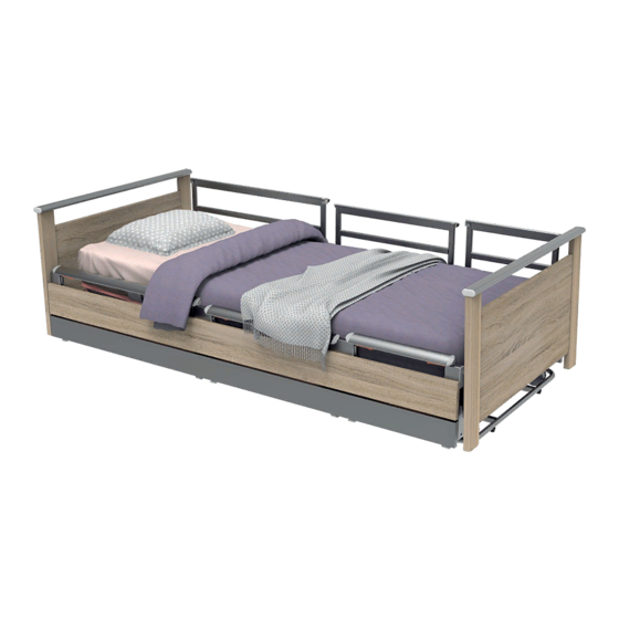
Page 19: Three Sections Siderails
Special screw to fix the board Remove board Three sections siderails The MMO bed 3500 is equipped with 3 sliding barriers on each side of the bed. There are three independent segments for partial or complete closure of the bed. They also provide support for exiting the bed. -
Page 20: Product Description
when all the barrier segments are raised up, the resident cannot get out of the bed Make sure its pathology allow the use of these restraints. Product description Basic equipment: Variable height and electric backrest • A movement of the backrest of 23 cm specially designed to reduce friction on skin of •... -
Page 21: Dimensions
4 Segment removable deck 4 Styles removable foot and Infra red hand set captor head board 3 segments siderails set 8 x 75 mm doble castors Bilateral Braking at angle Automatic brake at low position Dimensions Dimensions Observations Height of deck in high position 81 cm (castors Ø... -
Page 22: Technical Specifications
7.2 Technical specifications MECANIC 250 kg (215 kg patient, 20 kg mattress and 15 kg Safe working load accessories mattress) Two directional wheels 100mm in front and 4 Basic wheels multi directional 75 mm wheels on the foot 8 wheels Ø75mm double castor multi directional. Optional wheels swivel in front if central braking ELECTRIC... -
Page 23: Maintenance Specific To The Electronic Parts And Actuator Linak
Head and footboard • Barriers • Deck and mattress • Patient helper • IV pole • Castors • Brake pedals • 7.4 Maintenance specific to the electronic parts and actuator LINAK Maintenance: valid for all products LINAK • LINAK products must be cleaned at regular intervals to remove dust and dirt, and must be inspected for any damage, wear and breakage. -
Page 24: Use Of Different Product Features
The actuator / column should not be loaded beyond the values indicated on the • product label. The service factor indicated on the label must be respected. In the case of an • overrun, the product can be damaged, thus reducing its lifetime or destroy it. Unless otherwise stated on the product label, the maximum duty cycle is 10%, or 2 minutes maximum continuous use followed by 18 minutes of rest. -
Page 25: Articulation Of The Bed Deck
In its lowest position, the deck is 25cm from the floor (27cm with 100mm castors). The bed can be positioned at any height between the highest and lowest positions. 25 cm Comfortable bed exit position: The height where the patient is most comfortable to get out can be programmed. - Page 26 Backrest alone simultaneous move The MMO 3500 beds are equipped with a safety flattening and can have a CPR function that is on option. This is equipped with a damper to slow the descent to avoid shocks. An electrical CPR is possible using the two button of the back rest.
-
Page 27: Electrical Thigh Section And Manual Calf Section
Operating CPR function with a patient: The following operation should be performed if the bed is occupied. The electric backrest will operate normally. Lower the side rails if they are raised. Hold the backrest by the handles in the corners of the deck throughout the operation. Pull the orange handle at the central portion of each side of deck until the backrest is completely flat. -
Page 28: Comfort Position
To tilt the calf section up use the handle on the side of the deck and lift it to the desired position. To lower, raise the calf section slightly to release the catch and lower it to the horizontal. For the mono block leg section do the same as explain for the calf section Ensure that the calf section is in low position before lowering the thigh section to avoid an inverse folding and discomfort to the patient. -
Page 29: The Chair Position 1 Button
8.5 The chair position 1 button The chair position allows the resident sitting. It combines the comfort and the Trendelenburg position in a continuous cycle, using only one button. Handling: setting chair position is carried out using the hand pendant. Press the comfort to the maximum setting position shifts thighs, then keep hitting the same comfort button until the Trendelenburg movement causes the bed chair position. -
Page 30: Night Light Function Under The Bed
Night light function under the bed The nightlight function turns on a LED under the mattress to prevent falling while coming out of the bed at night Handling the ignition of the Nightlight is done using the hand pendant. Press the 2 buttons simultaneously lowering the bed and raised legs, a small button with a drawing of a blue lamp. -
Page 31: Brakes
Protection of the wall It is advised to respect a distance of 30 cm from the wall when installing the bed. This way when the Trendelenburg function is used the bed will not touch the wall. To help you visualize this, the wall bumper has an integrated ruler. If you remain in the green distance the bed will not touch the wall in reverse Trendelenburg position. -
Page 32: Transferring The Patient In The Bed
8.11 Transferring the patient in the bed The MMO 3500 is equipped with directional wheel on the head of the bed. This helps moving around tight corridors or on long distances with or without the patient. -
Page 33: Moving The Bed
Operation: If the bed has the multidirectional wheel at the head, put brakes on head wheels. This will prevent lateral move of the bed but forward and backward moves are still possible. Warning: It is recommended to move the bed at a speed appropriate to avoid shock or damage to the element of the bed. -
Page 34: Initialization Procedure In Case Of Loss Of Position By Height
Knee break: put the knee in lowest position rise it to the highest position Hi low: put the bed in lowest position rise it to the highest position Reset procedure is done. 8.15 Initialization procedure in case of loss of position by height An audible signal actuator indicates that the bed has lost its position ( it does not know where it is at) Loss of position is due to a malfunction of memory or improper initialization and is only for... -
Page 35: Riser For Barriers 3 Segments
Riser for barriers 3 segments If using a mattress thicker than 17cm you can use these side rails raiser. This accessory allows sealing the spaces between the bars and thus avoiding the risk of jamming of the patient in the barriers. It is padded on the inside to absorb shocks from limbs of patient. -
Page 36: Remote And Hand Pendant Support
Identification label on the bottom right of each board 9.8 Bed extension MMO 3500 could be equipped in option with 18 cm bed extension. An extension mattress block have to be used to ensure patient comfort. (On manual knee break bed version, the legs segment is not adjustable) -
Page 37: Linen Holder
Warranty 10.1 The MMO 3500 bed is guaranteed for parts, labor and transport for a period of 10 years, on the condition that the bed is used in accordance with the instructions and recommendations defined by the manufacturer. Excluded from this guarantee: all electromechanical parts (Motors, electrical control box, gas and electric actuators, remote controls and hand pendant controls, batteries, wheels, HPL plates, head and foot boards). -
Page 38: Installation And Commissioning
Intensive use of electric bed functions beyond the recommended service factor. Use of a bed that indicates a mechanical or electrical malfunction The manufacturer, assembler or fitter may not be held responsible for the safety, reliability or the characteristics of the device unless: The electrical system within the area accommodating the bed complies with the relevant recommendations, and the device is used in accordance with the instructions for use. -
Page 39: After Sales Service
Medtsrom Healthcare: 2 Cygnus Court, Beverley Road, Pegasus Business Park, Castle Donington, DE74 2SA Tel: 0845 3711717 Email: sales@medstrom.co.uk www.medstrom.co.uk Conditions of on-site assistance and spare parts supplies 11.2 If the bed is under guarantee and the fault is within the scope of the conditions specified in chapter 9.1, the supply and shipping of the part (if the faulty part is sent back to the... -
Page 40: Bed Identification Label
The types of intervention depend on your local service center. Spare parts will be shipped from factory within 48h from the receipt of orders. If the part is not in stock, or if it is not included in the list of spare parts, our ASS will inform you of the delay required for supply. Caution: The spare parts price list is reviewed on an annual basis. - Page 41 MMO3000 SPARE PARTS FO_QA_012 BASE DESCRIPTION DRAWING NR PREPARED HEAD ROLLER RP5T8319 600226 SUPPORT PREPARED FOOT ROLLER RP5T8314 600227 SUPPORT BASE ARM RP5F4752 207994 SMALL COMPENSATION RP5F4750 208008-5EA5 CONNECTING ROD ASSEMBLED BRAKE PEDAL RP5T7084 208113-5EA5 SPIDER ROLLER RP5F1672 147913 VH ARM SPINDLE RP5F4785 208009 CIRCLIP HUB CAPS Ø14...
- Page 42 SPARE PARTS MMO3000 FO_QA_012 PREPARED HEAD ROLLER SUPPORT DESCRIPTION DRAWING NR RP5F6830 208045-5EA5 ROLLER SUPPORT SWIVEL CASTOR Ø75 S-BRAKE QC9T5151 10379 CHC SCREW QC9F8170 200033 HFR NUT QC9D8148 9028 HEXAGON NUT COVER QC9F6172 209535 FLAT WASHER Z QC9D8386 9225 RP5F6868 208048 HEAD FORK TORSION SPRING RP5F6836...
- Page 43 MMO3000 SPARE PARTS FO_QA_012 PREPARED HEAD ROLLER SUPPORT DESCRIPTION DRAWING NR RP5F6830 208045-5EA5 ROLLER SUPPORT SWIVEL CASTOR Ø75 S-BRAKE QC9T5151 10379 CHC SCREW QC9F8170 200033 HFR NUT QC9D8148 9028 HEXAGON NUT COVER QC9F6172 209535 FLAT WASHER Z QC9D8386 9225 RP5F6868 208048 HEAD FORK TORSION SPRING SPINDLE...
- Page 44 MMO3000 SPARE PARTS FO_QA_012 BASE DESCRIPTION DRAWING NR PREPARED HEAD ROLLER RP5T6491 600190-5EA5 SUPPORT PREPARED FOOT ROLLER RP5T6487 600191-5EA5 SUPPORT BASE ARM RP5F4752 207994 SMALL COMPENSATION RP5F4750 208008-5EA5 CONNECTING ROD ASSEMBLED BRAKE PEDAL RP5T7084 208113-5EA5 SPIDER ROLLER RP5F1672 147913 VH ARM SPINDLE RP5F4785 208009 E CLIP HUB CAPS Ø14...
- Page 45 SPARE PARTS MMO3000 FO_QA_012 PREPARED HEAD ROLLER SUPPORT DESCRIPTION DRAWING NR RP5F7546 208078-5EA5 ROLLER SUPPORT ROLLER SUPPORT PLATE RP5F7565 208079-5EA5 SWIVEL CASTOR Ø100 S-BRAKE QC9F8169 200032 CHC SCREW QC9F8170 200033 HFR NUT QC9D8148 9028 HEXAGON NUT COVER QC9F6172 209535 FLAT WASHER Z QC9D8386 9225 RP5F6868...
- Page 46 SPARE PARTS MMO3000 FO_QA_012 PREPARED HEAD ROLLER SUPPORT DESCRIPTION DRAWING NR RP5F7546 208078-5EA5 ROLLER SUPPORT ROLLER SUPPORT PLATE RP5F7565 208079-5EA5 SWIVEL CASTOR Ø100 S-BRAKE QC9F8169 200032 CHC SCREW QC9F8170 200033 HFR NUT QC9D8148 9028 HEXAGON NUT COVER QC9F6172 209535 FLAT WASHER Z QC9D8386 9225 RP5F6868...
- Page 47 SPARE PARTS MMO3000 FO_QA_012 FRAME WITH EXTENSION DESCRIPTION DRAWING NR BED EXTENTION BED RP5T6078 600234 ASSEMBLED BED FRAME RP5T5048 208055-5EA5 PREPARED EXTENSION ROD RP5T5060 600212 SIDE COVER RP5F8022 200024-5EA5 Page 47 sur 71...
- Page 48 SPARE PARTS MMO3000 FO_QA_012 FRAME DESCRIPTION DRAWING NR ASSEMBLED BED FRAME RP5T5048 208055-5EA5 Page 48 sur 71...
- Page 49 SPARE PARTS MMO3000 FO_QA_012 BACKREST DESCRIPTION DRAWING NR BACKREST ASSY RP5S9850 600237 BACKREST ARCH RP5D9410 40328 CPR ASSY RP5F0015 39144 FORK BODY Ø10 L400 C220 QC9F0036 253142 RP5F3126 155382 BACKREST LINK Page 49 sur 71...
- Page 50 SPARE PARTS MMO3000 FO_QA_012 LEG REST DESCRIPTION DRAWING NR LEG REST EXTENSION RP5T7093 600238 LEG REST FRAME (MOBILE) RP5T6246 600239 LEG REST FRAME (FIX) RP5T6247 600240 THIGHT FRAME ASSY RP5S9522 41649-5EA5 QC9D2460 12992 TELESCOPIC LIFT-UP FITTING Page 50 sur 71...
- Page 51 SPARE PARTS MMO3000 FO_QA_012 LEG REST DESCRIPTION DRAWING NR ASSEMBLED TIBIA LIFT FRAME RP5T7320 41678-5EA5 ASSEMBLED BACKREST FRAME RP5S9522 41649-5EA5 QC9D2460 12992 TELESCOPIC LIFT-UP FITTING Page 51 sur 71...
- Page 52 PIECES DETACHEES MMO 3000 FO_QA_012 SPARE PARTS SLEEP DECK DESCRIPTION DRAWING NR BACKREST SLEEP DECK RP5T7072 600137 FIX SECTION SLEEP DECK RP5T7073 600138 LEG SECTION SLEEP DECK RP5T7074 600139 FOOT SECTION SLEEP DECK RP5T7075 600140 MATTRESS RETAINER RP5F7702 67334-5EA5 QC9F8898 67304 RUBBER BUNG Page 52 sur 71...
- Page 53 PIECES DETACHEES MMO 3000 FO_QA_012 SPARE PARTS SLEEP DECK WITH EXTENTION DESCRIPTION DRAWING NR BACKREST SLEEP DECK RP5T7072 600137 FIX SECTION SLEEP DECK RP5T7073 600138 LEG SECTION SLEEP DECK RP5T7074 600139 TIBIA SECTION SLEEP DECK RP5T7226 600141 MATTRESS RETAINER RP5F7702 67334-5EA5 QC9F8898 67304...
- Page 54 PIECES DETACHEES MMO 3500 FO_QA_012 SPARE PARTS 3 SEGMENT SIDE RAIL DESCRIPTION DRAWING NR HEAD SECTION HANDLE RP5F6988 158321-5EA5 RP5F6857 158320-5EA5 CENTRAL SECTION HANDLE FOOT SECTION HANDLE RP5F6989 158322-5EA5 LEFT SIDE TRIGGER RP5F7825 158366 RIGHT SIDE TRIGGER RP5F7810 158365 LEFT SIDE SHORT TRIGGER...
-
Page 55: Maintenance Guide For Medical Beds Levels 1 & 2
14 Maintenance guide for medical beds Levels 1 & 2 14.1 Manufacturer’s comitment: Warranty: Furniture: 10 years guaranteed against defects or failure under normal use conditions. Mattresses: guaranteed 2 years Electromechanical parts (engines, gas and electric actuators, remote controls, wheel of medical beds, thermoformed plates) are guaranteed 5 years. -
Page 56: Preventive Maintenance
The MMO 3500 bed does not require any particular preventative maintenance as regards the replacement of worn parts. Nevertheless, in order to maintain optimum function efficiency and operation safety, the bed must be inspected on a regular basis. - Page 57 OR OUR HOTLINE IN FRANCE +33 (0)811 900 035 Check List Medical Bed Identification of medical device Hospital Category: MEDICAL BED Brand/Model/Type: MMO 3500 Serial n° : Department / Location: Date of Manufacture: Qualitative aspects Operational and visual checks OVERALL CONDITION Availability of user manual and technical manual Good overall condition (bedends, protecting buffers, bed platforms, castors…)
- Page 58 The side rails fitted are designed for this particular bed and meet the operational requirements MECHANICAL FEATURES Absence of noise annoyance (creaking, lubrication..) Torque checks (nuts and bolts, pins, pivots, clips...) Proper condition of lifting pole (attachment and strap) Proper condition of mechanical wires Proper condition of bed platform Proper operation of leg raiser Proper operation of calf section...
-
Page 59: Servicing
Conclusion Operational Action required (refer to comments) Recommended date of next inspection: Operator Hospital Name: Signature : Date : 15 Servicing Only facility-authorized maintenance staff may perform the maintenance tasks described in this chapter. Unauthorized or untrained staff risk injury or electrical shock. Before carrying out the necessary maintenance tasks, and after having put the bed into the required position, if the bed is equipped with backup batteries, it must be unplugged from its power source and all its electrical functions must be locked-... - Page 60 The most common types of fault are given below to help reduce troubleshooting time. / None of the bed functions are operational The green LED on the power supply unit is illuminated Steps 5 to 9 - Yes Steps 1 to 4 1 Check to ensure the bed is connected to the mains 2 Check the power supply wire to ensure it is not crushed or cut, and that it is connected to the power supply unit.
- Page 61 7. Replace the power supply unit. Invert 2 motor inputs on the power supply unit (connections marked 2, 3 or 4 on the wiring diagram).The faulty function is now operational and the function corresponding to the inverted input does not work. Replace the power supply unit. IF No ↓...
-
Page 62: Second Level - Wiring Diagram
Fatal Error (error detected in one or more cylinders): Simultaneously press the 2 buttons on 2nd line of the hand pendant. An intermittent signal sounds, maintain pressure until disappearance of the signal. Replace the high maximum position and then bed down in the down position. - Page 63 SPARE PARTS MMO 3500 FO_QA_012 WIRING DIAGRAM 92817 207796 9933 207515 207514 92817 92818 PRICE 141290 150928 21554 11247 40449 21541 141261 PRICE 21541 PRICE Page 63 sur 71...
-
Page 64: Replacement Of The Patient Hand Pendant(Refer To Wiring Diagram)
15.3 Replacement of the patient hand pendant(refer to wiring diagram) Raise the bed to the maximum high position, if possible, then unplug the bed from its power source. Remove the mattress and the central section of the bed platform to access the power supply unit. -
Page 65: Replacing The Variable Height Motor
5. Put the new motor into position and re-connect the clevis pins. 6. Put the circlips back into position and check to ensure they rotate freely in their groove. 7. Plug motor 8. Plug the bed back into its power source and check for proper operation. 15.5.3 Replacing the variable height motor Caution: This procedure requires special precautions as the variable height motor connects the frame assembly to the bed platform. -
Page 66: Replacing A Backup Battery
15.5.6 Replacing a backup battery 1. Put the bed in max high position if possible and then unplug it. 2. Remove the mattress and take up the chest part of the deck to access the battery. 3. Unlock the power cord of the battery and unplug it from the control box. 4. - Page 67 MMO 5000 medical bed is designed to be used in the electronic environment specified below. The user must ensure that it is used in that environment. level of Electromagnetic CEI 60601 Immunity test compliance environment guide Security level The floor should be wood, Electrostatic concrete or tiled.
- Page 68 Page 68 sur 71...
-
Page 69: Disposal At End Of Product Life
Recommended separation distances between portable Radio Frequency communications equipment and mobile equipment The hospital bed is intended for use in an electromagnetic environment in which radiated RF disturbances are controlled. Users of hospital bed can help prevent electromagnetic interference by maintaining a minimum distance between the bed and RF communications equipment (transmitters) and the hospital bed as recommended below, according to the maximum output power equipment communication. - Page 70 Page 70 sur 71...
-
Page 71: Manufacturer's Detail
MMO. UK DISTRIBUTOR AND AFTER SALE SERVICE: MEDSTROM HEALTHCARE 2 Cygnus Court, Beverley Road, Pegasus Business Park, Castle Donington, DE74 2SA Tel: 0845 3711717 Email: sales@medstrom.co.uk www.medstrom.co.uk Page 71 sur 71...
Need help?
Do you have a question about the MMO 3500 and is the answer not in the manual?
Questions and answers