
Subscribe to Our Youtube Channel
Related Manuals for DEWESOFT DSI - LVDT

Summary of Contents for DEWESOFT DSI - LVDT
- Page 1 DSI - LVDT Technical Reference Manual, Version: 2.1., Date: 19.04.2019 DEWESoft d.o.o. Gabrsko 11a, 1420 Trbovlje, Slovenia www.dewesoft.com support@dewesoft.com...
-
Page 2: Table Of Contents
CONNECTORS ..........................6 Input connector pinout ............................ 6 Output connector pinout ..........................7 OPERATION ............................. 8 Connections ..............................8 DSI ADAPTERS / TEDS SENSOR SUPPORT ..................9 Manual operation ............................10 DOCUMENTATION VERSION ......................11 TABLE OF FIGURES ........................... I www.dewesoft.com... -
Page 3: Table Of Contents
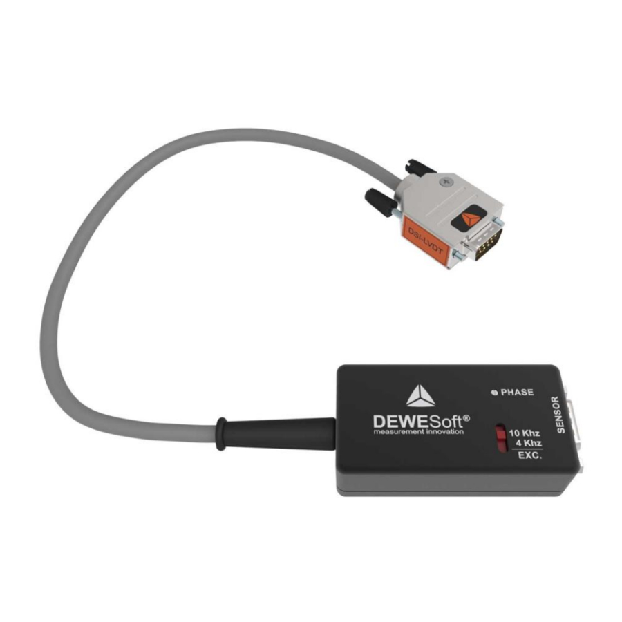
1 Technical data Electrical specifications DSI - LVDT adapter is powered by EXC voltage. LVDT adapter is compatible with SIRIUS(i) (variable EXC) or DEWE 43A type instrument (fixed +/-5V EXC). Power supply Exc. Voltage 10V – 15V, from EXC+ to EXC- outputs Power supply Exc. -
Page 4: Output Bandwidth - Magnitude And Phase Response
Output bandwidth - Magnitude and Phase response Magnitude response - 4kHz EXC (1-2000 Hz) 1000 Frequency (Hz) Typical magnitude response for 4kHz EXC Phase response - 4kHz EXC (1-2000 Hz) 1000 Frequency (Hz) Typical phase response for 4kHz EXC 2 / 11 www.dewesoft.com... -
Page 5: Typical Magnitude Response For 10Khz Exc
Magnitude response - 10kHz EXC (1-2000 Hz) 1000 Frequency (Hz) Typical magnitude response for 10 kHz EXC Phase response - 10kHz EXC (1-2000 Hz) 1000 Frequency (Hz) Typical phase response for 10kHz EXC 3 / 11 www.dewesoft.com... -
Page 6: Theory Of Operation
Theory of operation DSI - LVDT Adapter uses a unique ratiometric architecture to eliminate several of the disadvantages associated with traditional approaches to LVDT interfacing. The benefits of this new circuit are: minimal adjustments are required; temperature stability is improved; and transducer interchangeability is improved. -
Page 7: Lvdt Adapter Output Sensitivity To Input Signal Phase Lead/Lag, 1:1 Sensor
When phase compensation matches phase lead / lag of sensor output LVDT adapter output will be at its maximum = 0,5 (=1Vexc ∙ sensitivity ∙ 1,00). Example: 45⁰ sensor output, Example: 45⁰ sensor output, no compensation 45⁰ compensation 5 / 11 www.dewesoft.com... -
Page 8: Connectors
Adapter Output (Ground) - Out+ O, Signal Adapter Output (Single ended) + I, Power Power Supply - MGND I Mechanical Ground, chassis TEDS I/O, Signal TEDS AGND Analog Ground Reser. Reserved / Not Connected Lemo 8-pin plug 6 / 11 www.dewesoft.com... -
Page 9: Output Connector Pinout
Sensor Output - I, Signal Sensor Output + Exc- O, Power Sensor supply, excitation - MGND I Mechanical Ground, chassis Reser. I/O, Signal Reserved / Not Connected AGND Analog Ground Reser. Reserved / Not Connected Lemo 8-pin receptable 7 / 11 www.dewesoft.com... -
Page 10: Operation
* Input - (pin7) shall be connected to half bridge completion resistor divider assembled with discrete resistors with the following recommended specifications: Resistance 1kΩ, Tolerance 0.1%, Temperature coefficient 15ppm, Power 0,125W. This connection is preferred over the previous connection IN- to GND (so called “noisy GND”). Solder side of the DB9 male, HB divider resistors 8 / 11 www.dewesoft.com... -
Page 11: Dsi Adapters / Teds Sensor Support
EXC. Voltage will be set automatically. Please check if you are using the latest software where LVDT Adapter is supported. Options - Setting s DSI adapters/TEDS sensors checkbox DSI-LVDT adapter is recognized and set automatically 9 / 11 www.dewesoft.com... -
Page 12: Manual Operation
If DSI adapters/TEDS sensors is left unchechked under Hardware setup then sensor supply and range has to be set manualy. DSI adapters/TEDS sensors checkbox is left unchecked Under Channel setup for channel N, set Excitation voltage from 10V to 15V maximum according to Electrical Specifications. Excitation voltage setting 10 / 11 www.dewesoft.com... -
Page 13: Documentation Version
5 Documentation version Doc-Version Date Notes [dd.mm.yyyy] 20.01.2016 Initial version 20.11.2017 Change: General document template MSI-LVDT to DSI-LVDT LVDT adapter signals 19.04.2019 Add: Output bandwidth - Magnitude and Phase response Change: 3.1 Connections: HB divider resistors 11 / 11 www.dewesoft.com... -
Page 14: Table Of Figures
Solder side of the DB9 male, HB divider resistors ............... 8 Options - Settings ........................9 DSI adapters/TEDS sensors checkbox ..................9 DSI-LVDT adapter is recognized and set automatically ............... 9 DSI adapters/TEDS sensors checkbox is left unchecked ............10 Excitation voltage setting ......................10 I / I www.dewesoft.com...
Need help?
Do you have a question about the DSI - LVDT and is the answer not in the manual?
Questions and answers