
Summary of Contents for Big Joe PTE 30 Series
- Page 1 PTE 30 SERIES SELF-PROPELLED, PALLET LIFT TRUCK Operation Maintenance Repair Parts List Big Joe Manufacturing Company • Des Plaines, IL 60018 MANUAL NO. 901467 06/20/2017...
- Page 2 WARNING Do not operate this truck unless you have been autho- Always look in direction of travel. Keep a clear view, rized and trained to do so, and have read all warnings and when load interferes with visibility, travel with load and instructions in Operator’s Manual and on this trailing.
-
Page 3: Table Of Contents
TABLE OF CONTENTS Section Page Section Page 1 DESCRIPTION ............1-1 6 BRAKE SERVICING ........... 6-1 1-1. INTRODUCTION..........1-1 6-1. BRAKES............6-1 1-2. GENERAL DESCRIPTION.......1-1 6-1.1. BRAKE REMOVAL.......... 6-1 1-3. SAFETY FEATURES........1-2 6-1.2. BRAKE INSTALLATION........6-1 2 OPERATION ...............2-1 7 TRANSMISSION, DRIVE WHEEL, LOAD 2-1. - Page 4 TABLE OF CONTENTS - Continued Section Page Section Page 10-3. EMERGENCY DISCONNECT SWITCH 10-7.4.TEST THE FAULT DETECTION CIRCUITRY10-6 REPLACEMENT..........10-2 10-7.5.PANEL REMOVAL......... 10-6 10-4. DEADMAN SWITCH........10-2 10-7.6.PANEL DISASSEMBLY......... 10-6 10-4.1.REPLACEMENT ..........10-2 10-7.7.PANEL INSTALLATION......... 10-7 10-4.2.ADJUSTMENT..........
-
Page 5: Description
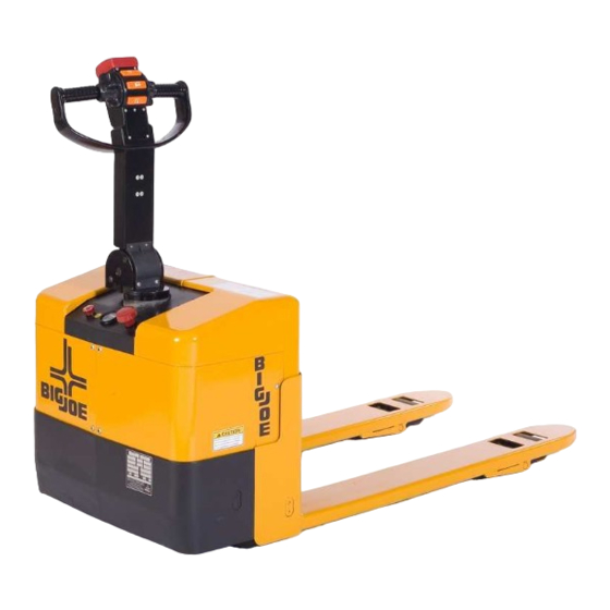
The lift truck must be pro- tected from the elements. This publication describes the 24 volt transistor PTE 30 lift truck distributed by Big Joe Manufacturing The model number will be found on the name plate Company, Des Plaines, Illinois, 60018. Included are... -
Page 6: Safety Features
1-3. SAFETY FEATURES. • Separately fused control circuits and power circuits. The PTE 30 is designed and engineered to provide • Readily accessible HORN button. maximum safety for operator and payload. Some of • Slip-resistance hand to provide a firm hand hold for the safety features incorporated into the design are: operator. -
Page 7: Operation
SECTION 2 OPERATION 2-1. GENERAL. • Do not overload truck. Check nameplate for load weight and load center information. This section gives detailed operating instructions for the PTE 30 lift truck. The instructions are divided into • Before lifting, be sure load is centered, forks are the various phases of operations, such as operating completely under load, and load is as far back as lift, driving, and stopping. - Page 8 Table 2-1 Operator Checks ITEM PROCEDURE ITEM PROCEDURE Wheels Check drive wheel for cracks or Transmission and Check for signs of fluid leakage. damage. Move truck to check hydraulic sys- load for freedom of rotation. tems. Hydraulic Check operation of lift and lower Forks Check for cracks and damage.
-
Page 9: Sample Of Operator Check List
Electric Truck Daily Operator Check-Off List Big Joe Manufacturing Company Date Operator Truck No. Model No. Dept. Shift Hour Meter Reading Drive Hoist Check O.K. ( ) Need Maintenance Tires Load Wheels Horn Lift Lower Control Attachment Operation Forward & Reverse Controls... -
Page 10: General Control Operation
2-4. GENERAL CONTROL OPERATION. when the handle is released and spring action raises steering arm to the upright position. The speed control (See Figure 2-2) located on each side of the control head provides fingertip control for driving the truck. Rotate the control in the direction you want to travel. -
Page 11: Steering Arm Pneumatic Spring
2-8. LIFT AND LOWER CONTROLS. Lift/Lower Control buttons are located on the steering control head. (Figure 2-3) To lift forks, push in LIFT button and hold until forks reach desired height. To lower forks, push in LOWER button and hold until forks descend to desired height. 2-9. - Page 12 NOTES 901467...
-
Page 13: Planned Maintenance
DO NOT attempt to charge the bat- accordingly. These procedures must be performed by teries. Contact appropriate personnel for repairs a qualified service technician or your Big Joe service to be made. representative. Connect the charger to connector (13, Figure 12- 9). -
Page 14: Lubrication
3-5. LUBRICATION. Table 3-2 Recommended Lubricants (See Table 3-3 for Application) Refer to Table 3-2 for the recommended types of No. 1 Transmission oil—EP SAE 80W-90, grease and oil. Table 3-3 in conjunction with Figure 3-1 Part Number 055780 identifies the items requiring lubrication. Transmission oil—EP SAE 10W-30, Part Number 055790 (Note) No. -
Page 15: Lubrication Diagram
R6527 Figure 3-1 Lubrication Diagram Table 3-3 Lubrication Chart FIG 3-2 LOCATION METHOD OF TYPE APPLICATION INDEX APPLICATION (Table 3-3) LUBRICANT Steering arm pivot No. 4 1 or 2 drops each time serviced. Lift Linkage * No. 4 1 or 2 drops each time serviced. Lift Linkage Fittings** No. - Page 16 NOTES 901467...
-
Page 17: Troubleshooting
SECTION 4 TROUBLESHOOTING 4-1. GENERAL With Braking: Trouble With Lifting Or Lowering, and Miscellaneous malfunctions. Refer to electrical wiring Table 4-1 services as a guide to determine possible schematic (Figure 4-5) as a supplement to the trouble- causes of trouble. The table is divided into five main shooting chart or when tracing an electrical circuit. - Page 18 Table 4-1 Troubleshooting Chart - Continued MALFUNCTION PROBABLE CAUSE CORRECTIVE ACTION Truck runs forward and in reverse Defective potentiometer (14, Fig- Check for variable resistance at at lower speeds; will not run at 12-4) in control head. the potentiometer when direction high speed.
- Page 19 Table 4-1 Troubleshooting Chart - Continued MALFUNCTION PROBABLE CAUSE CORRECTIVE ACTION TROUBLE WITH LIFTING OR LOWERING - Continued Platform does not lift to top. Pump a. Oil level too low. Add oil to reservoir. motor runs. b. Load larger than capacity. Refer to nameplate on side of mast for maximum load capacity.
-
Page 20: Transistor Controller
4-2. TRANSISTOR CONTROLLER TROUBLE- SHOOTING 4-2.1. Fault Detection. The controller provides diagnostics information to assist technicians in troubleshooting drive system problems. When a fault is detected, the appropriate fault code is signaled via the LED, externally visible on the side of controller (See Figure 4-1 for LED location on controller). -
Page 21: 4-2.2. Hand Held Programmer (Optional)
The programmer (Part Number If a programmer is available, connect it to the pro- 005472-02) is available through your Big Joe dealer. If grammer connector (Figure 4-3) on the controller. -
Page 22: 4-2.6. Adjustment
"Monitor" menu. Select the Monitor mode by pressing the "Right" arrow on the Navigation key. Press the Navigation key "Down" arrow to scroll down to observe the status of the forward, reverse, brake, emergency reverse, and mode switches. Cycle each switch in turn, observing the programmer. -
Page 23: 4-2.7. Diagnostics And Troubleshooting
Table 4-2 Adjustment Settings The codes are listed in Table 4-3. The "0" 's in Table indicate an illuminated LED. For suggestions Function Setting about possible causes of the various faults, refer to Table 4-4 Troubleshooting Chart. Acceleration Rate (M1 thru M4) 2.0, 2.0, Operational faults, such as an over-temperature situa- 0.5, 0.5... - Page 24 Table 4-3 LED Codes LED Code Explanation LED Off Not illuminated No power or defective controller Solid On Always on Defective controller Single Flash Controller operational, no faults 1 - 2 0 00 Hardware fail-safe error 1 - 3 0 000 M- fault or motor output short 1 - 4 0 0000...
- Page 25 Table 4-4 Troubleshooting Chart PROGRAMMER POSSIBLE CAUSE FAULT CLEARANCE CODE LCD DISPLAY NO KNOWN FAULTS CURRENT SHUNT 1. Abnormal vehicle operation causing high current Cycle KSI. If problem persists, replace controller. FAULT spikes. 2. Current sensor out of range. 3. Controller failure. HW FAILSAFE 1.
- Page 26 Table 4-5 Troubleshooting Chart - Continued LOW BATTERY VOLT- 1. Battery voltage < undervoltage cutback. When voltage rises above undervoltage cutoff point. 2. Corroded battery terminal. 3. Loose battery or controller terminal. OVERVOLTAGE 1. Battery voltage > overvoltage shutdown limit. When voltage falls below overvoltage cutoff point.
- Page 27 NOTES 901467 4-11...
-
Page 28: Wiring Diagram (Sheet 1)
R6490A Figure 4-5 Wiring Diagram (Sheet 1) 4-12 901467... - Page 29 R6490B Figure 4-5 Wiring Diagram (Sheet 1) 901467 4-13...
- Page 30 NOTES 4-14 901467...
-
Page 31: Steering Arm And Control Head Serivce
SECTION 5 STEERING ARM AND CONTROL HEAD SERIVCE 5-1. CONTROL HEAD 11. Install two screws (6) and two screw (7). 12. Install the switch leads in the control head con- 5-1.1. Control Head Removal. nector. Turn off the key switch (4, Figure 12-7), discon- 13. -
Page 32: Control Head Switches
Remove two nuts (10) and two washers (9) from Position mounting bracket (8) in the control head two screws (5). and install two screws (11). Remove the two screws (5) with switches (6) and Check that rollers on both switches (6) contact the block (7). -
Page 33: Control Head And Steering Arm
R6507 Figure 5-2. Control Head and Steering Arm 901467... -
Page 34: 5-1.5. Potentiometer Removal Testing And Adjustment
5-1.5. Potentiometer Removal Testing and Adjust- Position mounting bracket (13) in the control head ment. and install two screws (11). Set an ohmmeter to the RX1K (1000) scale and Remove the control head as described in para- connect across the potentiometer leads. graph 5-1.1. -
Page 35: 5-1.6. Control Head Installation
5-1.6. Control Head Installation. Remove clip (10) and pull pneumatic spring (9) from stud (11). Position control head (1, Figure 5-2) on arm (7) Remove four screws (8) to free pneumatic spring and feed the electrical harness into the control (9) from handle (7). -
Page 36: Steering Control
R6506 Figure 5-4 Steering Control 901467... -
Page 37: Brake Servicing
SECTION 6 BRAKE SERVICING 6-1. BRAKES. 6-1.2. Brake Installation. Position brake assembly (24) on the drive motor 6-1.1. Brake Removal. and secure with three screws (26) and three Remove the drive assembly as described in SEC- washers (25). TION Install the drive assembly as described in SEC- Remove three screws (26), three washers (25) TION... - Page 38 NOTES 901467...
-
Page 39: Transmission, Drive Wheel, Load Wheel, Balance Wheel And Entry Roller Servicing
7-1. or is cracked or damaged, replace the entire Remove four screws (1) and remove housing (2) load wheel and bearing assembly. Big Joe from the drive assembly. recommends that both load wheel assem- blies be replaced at the same time. This... -
Page 40: Drive Assembly
R6510 Figure 7-1 Drive Assembly 901467... -
Page 41: Fork Section
R6519 Figure 7-2 Fork Section 901467... -
Page 42: 7-3.2. Repair
7-3.2. Repair 7-3.3. Load Wheel Installation Remove seals (1, Figure 7-3) and rings (2) from Position load wheel assembly (12, Figure 7-2) in wheels (5). wheel housing (14). Remove bearings (4) from wheels (5). Install pin (3, Figure 7-3) and secure with screw Figure 7-2). -
Page 43: Casters
7-4. CASTERS Remove screw (18) and remove caster (20) from bracket (17 or 21). 7-4.1. Removal Remove nut (28), washer (27), sleeve (26), spring Remove four screws (9, Figure 12-7) and two (25), washer (24), screw (23) and washer (22) screws (8) and remove covers (7 and 10) from bracket (17 or 21). -
Page 44: Entry Rollers
7-5. ENTRY ROLLERS Remove nut (10, Figure 7-2), screw (7), and roller (9) from the fork tip. Entry rollers provide smoother transition in and out of Remove sleeve (8) from roller (9). the pallets. 7-5.2. Entry Roller Removal 7-5.1. Entry Roller Removal Install sleeve (8, Figure 7-2) in roller (9). -
Page 45: Elevation System Servicing
SECTION 8 ELEVATION SYSTEM SERVICING 8-1. GENERAL. 8-3. Power Section and Fork Section The elevation system includes the lift linkage, power 8-3.1. Separating Power Section and Fork section and fork section. Section. Support entire truck on blocking, providing sepa- 8-2. Lift Linkage rate blocks so that frame (3, Figure 8-2) can be... -
Page 46: Fork Section
Align bracket (24) with the holes in frame (3, Fig- Install covers (7 and 10, Figure 12-7) and secure 8-2) and insert pins (29). Secure pins (29) with four screws (9) and two screws (8). with screws (30). Turn on the keyswitch (4) and pull out switch (6). Remove hoist from fork frame (6, Figure 8-1). - Page 47 R6516A Figure 8-2 Frame 901467...
- Page 48 NOTES 901467...
-
Page 49: Hydraulic System Servicing
SECTION 9 HYDRAULIC SYSTEM SERVICING 9-1. LINES AND FITTINGS Refer to Figure 9-2 and remove leaking line or fit- ting and replace it with a new line or fitting. WARNING: When forks are raised, pressure exists in Remove breather (12) from the hydraulic reser- the hydraulic system lines and fittings. - Page 50 R6512 Figure 9-2 Hydraulic System 901467...
-
Page 51: Hydraulic Pump, Motor, And Reservoir Assy
9-2. HYDRAULIC PUMP, MOTOR, AND RESER- NOTE: The reservoir and hose will be filled with VOIR ASSY hydraulic oil. Place a container under the hose to catch any hydraulic oil. The hydraulic pump/motor assembly can be disas- sembled and repaired. However, a defective pump, 17. -
Page 52: 9-2.4. Lift Cylinder
20. Install covers (7 and 10, Figure 9-1) and secure with four screws (9) and two screws (8). Fill hydraulic reservoir by removing breather (12, Figure 9-2). Use approved Big Joe hydraulic fluid. 9-2.4. Lift Cylinder Reinstall breather (12). 9-2.4.1.Removal Install top plate (5, Figure 12-9) and secure with six screws (6). -
Page 53: 9-2.5. Hydraulic Pressure Adjustment
Lower forks as far as they will go. Fill hydraulic reservoir by removing breather (12). Remove four screws (9, Figure 9-1), two screws Use approved Big Joe hydraulic fluid. (8) and covers (7 and 10). Reinstall breather (12). Disconnect hose (1, Figure... - Page 54 NOTES 901467...
-
Page 55: Electrical Components
SECTION 10 ELECTRICAL COMPONENTS 10-1.KEY SWITCH REPLACEMENT. Install new switch (4) and secure with supplied nut. Turn off the key switch (4, Figure 10-1), push in Reconnect electrical leads, as noted during emergency disconnect switch (6). removal. Remove four screws (9), two screws (8) and cov- Reinstall the cover (3), four screws (2) and four ers (7 and 10). -
Page 56: Replacement
10-2.BATTERY INDICATOR REPLACEMENT. Unscrew the red knob from emergency discon- nect switch (6). Turn off the key switch (4, Figure 10-1), push in Remove four screws (1), four screws (2) and raise emergency disconnect switch (6). up cover (3). Remove four screws (9), two screws (8) and cov- Tag and disconnect electrical leads from emer- ers (7 and 10). - Page 57 R6506 Figure 10-2 Steering Control 901467 10-3...
-
Page 58: 10-4.2.Adjustment
10-4.2.Adjustment Remove two screws (11), washers (10), plate (7) and switch (31). Remove two screws (4, Figure 10-2) and cover Install new switch in reverse order of disassembly. (2). Remove two screws (16) and cover (14). 10-7.ELECTRICAL CONTROL PANEL Loosen two screws (21) and adjust switch (19) so that the brake applies as shown in Figure 10-3. - Page 59 R6516A Figure 10-4 Frame 901467 10-5...
-
Page 60: 10-7.3.Diagnostic History
10-7.3.Diagnostic History Leave the key switch on and remove the in-line fuse wire. The vehicle status should continue to The handheld programmer can be used to access the remain off. controller's diagnostic history file. When the program- Cycle the key switch off and on. Release the mer is connected to the unit, the error log file is auto- brake and apply the throttle. -
Page 61: 10-7.7.Panel Installation
10-7.7.Panel Installation. Reconnect the wires to key switch (4) as noted during removal. Install the control panel (34, Figure 10-4) and Secure cover (3) with four screws (1) and four secure with four screws (30). screws (2). Refer to wiring schematic (Figure 4-5) and con- 10. -
Page 62: Pump Motor
10-8.PUMP MOTOR. Remove the drive assembly as described in para- graph 7-2.1. The pump motor is replaceable but not repairable. Disassemble the drive assembly as described in Refer to paragraph 9-2. paragraph 7-2.2. 10-9.DRIVE MOTOR. Refer to Figure 12-6 for disassembly procedure. The drive motor exposed surfaces should be cleaned Remove the drive assembly as described in para- at least once a month to assure proper cooling of... -
Page 63: Optional Equipment
SECTION 11 OPTIONAL EQUIPMENT There is no optional equipment available at this time. 901467 11-1... - Page 64 NOTES 11-2 901467...
- Page 65 SECTION 12 ILLUSTRATED PARTS BREAKDOWN Following is an illustrated parts breakdown of assemblies and parts associated with the PTE 30 Lift Truck. 901467 12-1...
- Page 66 R6506 Figure 12-1 Steering Control 12-2 901467...
- Page 67 INDEX PART INDEX PART PART NAME REQD. PART NAME REQD. 902257 INNER COVER — STEERING ARM (FIGURE 12-3) — NOT USED 602289 OUTER COVER 902314 SCREW — NOT USED 902273 MOUNTING PLATE 902313 SCREW 902355 SPACER 902227 BUSHING 902377 SWITCH 902290 PIN SHAFT 902385...
- Page 68 R6507 Figure 12-2 Steering Arm 12-4 901467...
- Page 69 INDEX PART INDEX PART PART NAME REQD. PART NAME REQD. 902277 SCREW — CONTROL HEAD (FIGURE 12-3) 902294 PNEUMATIC SPRING 902204 SCREW 902401 CLIP 902185 WASHER 902402 STUD 902062 HANDLE 902234 COVER PLATE 902127 SCREW 902316 SCREW 902366 SPRING PIN 902254 HANDLE TUBE 901467...
- Page 70 R6461 Figure 12-3 Control Head INDEX PART INDEX PART PART NAME REQD. PART NAME REQD. 902164 . SPRING — 902040 CONTROL HEAD 902023 . BUTTON-HORN 902047 . COVER 902137 . SCREW 902174 . SWITCH 902045 . COVER 902163 . SPRING 902025 .
- Page 71 R6462 Figure 12-4 Control Head INDEX PART INDEX PART PART NAME REQD. PART NAME REQD. 902141 . SCREW — — CONTROL HEAD 902059 . GEAR 902104 . RACK 902079 . MOUNTING BRACKET 902165 . SPRING 902102 . POTENTIOMETER 902166 . SPRING PIN 902172 .
- Page 72 R6510 Figure 12-5 Drive Assembly INDEX PART INDEX PART PART NAME REQD. PART NAME REQD. 902218 BEARING 902326 SCREW 902275 MOUNTING PLATE 902295 POSITION HOUSING 902274 MOUNTING PLATE 902319 SCREW — TRANSMISSION, BRAKE AND 902342 SEAT HOUSING DRVIE MOTOR ASSY 902287 O-RING (FIGURE...
- Page 73 R6523 Figure 12-6 Transmission, Brake and Drive Motor Assy INDEX PART INDEX PART PART NAME REQD. PART NAME REQD. 902141 . SCREW — 902379 TRANSMISSION, BRAKE AND DRIVE MOTOR ASSY 902364 . SPRING — — . GEAR BOX . INSULATING PLATE —...
- Page 74 R6521 Figure 12-7 Compartment 12-10 901467...
- Page 75 INDEX PART INDEX PART PART NAME REQD. PART NAME REQD. 902239 EMERGENCY STOP BUTTON 902323 SCREW 902261 RIGHT PANEL 902400 SCREW 902314 SCREW 902268 MIDDLE PANEL 902320 SCREW 902070 KEY SWITCH 2001-116002 BATTERY INDICATOR 902260 LEFT PANEL 901467 12-11 Updated 06-20-2017...
- Page 76 R6524 Figure 12-8 Decals INDEX PART INDEX PART PART NAME REQD. PART NAME REQD. 061334 NAMEPLATE 056564 CAUTION DECAL 066050 DRIVE SCREW 056617 FORWARD-REVERSE DECAL 056632 BIG JOE DECAL 056499 NO RIDING DECAL 056613 OPER. INSTR. DECAL 12-12 901467...
- Page 77 NOTES 901467 12-13...
- Page 78 R6516A Figure 12-9 Frame 12-14 901467...
-
Page 79: Frame
INDEX PART INDEX PART PART NAME REQD. PART NAME REQD. — CASTER ASSEMBLY 902376 SUPPORT BRACKET (FIGURE 12-11) 902323 SCREW 902301 RIGHT CASTER MOUNTING 902245 FRAME BRACKET 902220 TOP PLATE 902392 WASHER 902321 SCREW 902335 SCREW 902272 MOUNTING PLATE 902393 WASHER 902378 SWITCH... - Page 80 R6519 Figure 12-10 Fork Section 12-16 901467...
- Page 81 INDEX PART INDEX PART PART NAME REQD. PART NAME REQD. 902399 WHEEL HOUSING 902217 BEARING 902343 SHAFT 902327 SCREW 902356 SPACER 902263 LINK 902344 SHAFT 902314 SCREW 902215 BEARING 902266 LOCK 902262 LINK 902244 FORK FRAME 902345 SHAFT 902337 SCREW 902338 SCREW 902350...
- Page 82 R6518 Figure 12-11 Caster Assembly 12-18 901467...
- Page 83 INDEX PART INDEX PART PART NAME REQD. PART NAME REQD. 902336 . SCREW — 902229 CASTER ASSEMBLY 902395 . WASHER 902372 . STEEL BALL 902219 . BEARING 902354 . SNAP RING 902396 . WHEEL 902279 . NYLON SLEEVE 902351 . SLEEVE 902280 .
-
Page 84: Load Wheel Assembly
R6520 Figure 12-12 Load Wheel Assembly INDEX PART INDEX PART PART NAME REQD. PART NAME REQD. 902347 . SHAFT — 902265 LOAD WHEEL ASSEMBLY 902211 . BEARING 902146 . SEAL 902264 . LOAD WHEEL 902108 . RING 12-20 901467... -
Page 85: Electrical Panel
R6517 Figure 12-13 Electrical Panel INDEX PART INDEX PART PART NAME REQD. PART NAME REQD. 902269 MOUNTING BRACKET 902226 BUSBAR 902042 CONTROLLER 902056 FUSE 902209 FUSE HOLDER 902238 ELECTRICAL PANEL 902037 CONTACT, LIFT 902225 BUSBAR — 902210 FUSE, 10 AMP 902037 CONTACT, MAIN 901467... - Page 86 R6512 Figure 12-14 Hydraulic System 12-22 901467...
-
Page 87: Pump, Motor & Reservoir Assembly
INDEX PART INDEX PART PART NAME REQD. PART NAME REQD. 902043 COVER 902255 HOSE 902405 BREATHER 902095 O-RING — NOT USED — CYLINDER ASSEMBLY (FIGURE 12-16) 902299 RESERVOIR 902331 SCREW 902332 SCREW — PUMP, MOTOR & RESERVOIR 902322 SCREW ASSEMBLY (FIGURE 12-15) 902309... - Page 88 R6467 Figure 12-15 Pump, Motor & Reservoir Assembly 12-24 901467...
- Page 89 INDEX PART INDEX PART PART NAME REQD. PART NAME REQD. 902232 . COUPLING — 902298 PUMP, MOTOR & RESERVOIR ASSEMBLY 902297 . PUMP ASSEMBLY 902256 . HYDRAULIC PUMP MOTOR 902129 . SCREW 902216 . BEARING 902318 . SCREW 902221 . BLOCK 902391 .
- Page 90 R6467 Figure 12-16 Cylinder Assembly 12-26 901467...
- Page 91 INDEX PART INDEX PART PART NAME REQD. PART NAME REQD. 902339 . SEAL — 902235 CYLINDER ASSEMBLY 902236 . CYLINDER BODY 902292 . PISTON ROD 902237 . DUST SEAL 901467 12-27...
- Page 92 R6513 Figure 12-17 Valve Assembly 12-28 901467...
- Page 93 INDEX PART INDEX PART PART NAME REQD. PART NAME REQD. — . VALVE CAP — 902381 VALVE ASSEMBLY 902284 . O-RING 902317 . SCREW 902360 . SPRING 902387 . WASHER — 902371 . SPRING SOCKET . VALVE BODY 902374 . STEEL BALL 902391 .
- Page 94 NOTES 12-30 901467...
- Page 96 Big Joe Manufacturing Company...
Need help?
Do you have a question about the PTE 30 Series and is the answer not in the manual?
Questions and answers