
Related Manuals for Motomaster 011-3003-0


Summary of Contents for Motomaster 011-3003-0
- Page 1 011-3003-0 BATTERY TESTER IMPORTANT: INSTRUCTION Please read this manual carefully before running this battery tester MANUAL and save it for reference.
- Page 2 This MotoMaster® product carries a one (1) year warranty against defects in workmanship and materials. At its discretion, MotoMaster® Canada agrees to have any defective part(s) repaired or replaced free of charge, within the stated warranty period, when returned by the original purchaser with proof of purchase.
-
Page 3: Safety Information
bars TABLE OF CONTENTS SAFETY INFORMATION KEY PARTS LIST IMPORTANT INFORMATION OPERATION tion tabs MAINTENANCE SPECIFICATIONS SAVE THESE INSTRUCTIONS This manual contains important safety and operating instructions. Read all instructions and follow them with use of this products... -
Page 4: Fire And Explosion Hazard
011-3003-0 | contact us 1-888-942-6686 INTRODUCTION WARNING! tabs FIRE AND EXPLOSION HAZARD This manual contains information that relates to PROTECTING PERSONAL SAFETY and • Make sure the area around the battery PREVENTING EQUIPMENT PROBLEMS. tester is free from spark or flame when Carefully read and follow the guidelines in this testing automotive batteries. -
Page 5: Battery Tester
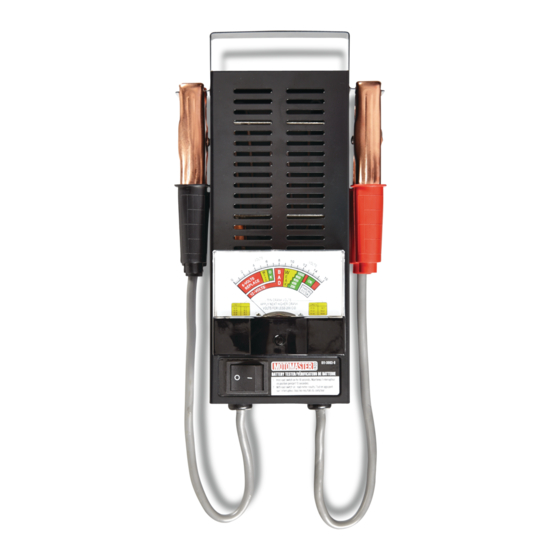
bars BATTERY TESTER Red (Positive) Cable Clamp Spring-loaded Switch Black (Negative) Cable Clamp Adjustment Screw tion tabs Meter Display... - Page 6 011-3003-0 | contact us 1-888-942-6686 Temperature compensation The MotoMaster 100 A Battery Tester is designed tabs tabs to test the voltage level and condition of all types This battery tester’s accuracy will be affected of 6 V and 12 V automotive lead-acid batteries and by cold temperatures.
- Page 7 bars Battery load test • Ensure the dial pointer (1) on the meter scale • Connect the negative (Black) clamp (1) of the is pointing at zero. If not, set the dial pointer battery tester to negative terminal (2) of the using the adjustment screw (2) (fig A).
- Page 8 011-3003-0 | contact us 1-888-942-6686 • Holding the spring-loaded switch in the ON position, check the 6-volts or 12-volts section (1) of the meter scale to identify the voltage level and condition of the battery (fig E).
- Page 9 bars Charging system test Battery Analysis • Turn off all the vehicle lights and electrical METER SCALE BATTERY CONDITION (CHARGING SYSTEM SECTION) accessories. Dial pointer indicates green (OK) band. The battery capacity is good. • Connect the positive (Red) clamp (1) of the The battery capacity is insufficient.
- Page 10 011-3003-0 | contact us 1-888-942-6686 Refer to this table for identifying minimum cranking voltage tabs tabs LOAD VOLTAGE MINIMUM CRANKING VOLTAGE (FROM BATTERY LOAD TEST) continuat 10.2 10.4 10.6 notes notes 10.8 11.0 11.2 10.2...
-
Page 11: Maintenance
bars Maintenance • After use, disconnect the positive and negative clamps of the battery tester from the battery terminals. • The positive and negative clamps of the battery tester are liable to come into contact with battery electrolyte. Clean and dry the exterior surface of the battery tester after use, to prevent accumulation of dust and dirt.
Need help?
Do you have a question about the 011-3003-0 and is the answer not in the manual?
Questions and answers