Table of Contents
Advertisement
Quick Links
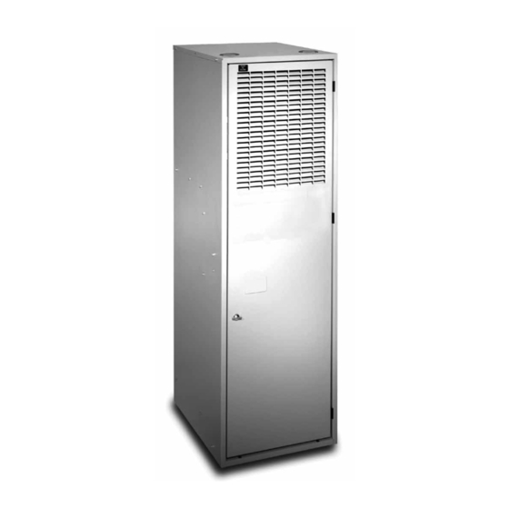
CMF95 Series Downflow Condensing Gas Furnace
INSTALLATION INSTRUCTIONS
Direct Vent (Sealed Combustion) Forced Air
For Installation in:
• Manufactured Homes
• Recreational Vehicles, Park Models, &
Manufactured Buildings
• Modular Homes/Buildings
WARNING:
FIRE OR EXPLOSION HAZARD
• Failure to follow safety warnings exactly
could result in serious injury or property
damage.
• Installation and service must be performed
by a qualified installer, service agency or the
gas supplier.
• Do not store or use gasoline or other
flammable vapors and liquids in the vicinity
of this or any other appliance.
WHAT TO DO IF YOU SMELL GAS
• Do not try to light any appliance.
• Do not touch any electrical switch; do not
use any phone in your building.
• Leave the building immediately.
• Immediately call your gas supplier from a
neighbor's phone. Follow the gas supplier's
instructions.
• If you cannot reach your gas supplier, call
the fire department.
DO NOT DESTROY THIS MANUAL. KEEP IN A SAFE PLACE FOR FUTURE REFERENCE.
AVERTISSEMENT
RISQUE D'INCENDIE OU D' EXPLOSION
• Le non-respect des avertissements de
sécurité pourrait entraîner des blessures
graves, la mort ou des dommages matériels.
• L'installation et l'entretien doivent être
effectués par un installateur qualifié, un
organisme de service ou le fournisseur de
gazstaller, service agency or the gas supplier.
• Ne pas entreposer ni utiliser de l'essence ni
d'autres vapeurs ou liquides inflammables
dans le voisinage de cet appareil, ni de tout
autre appareil.
QUE FAIRE S'IL Y A UNE ODEUR DE GAZ
• Ne pas tenter d'allumer aucun appareil.
• Ne toucher à aucun interrupteur électrique;
n'utiliser aucun téléphone dans le bâtiment.
• Évacuer l'immeuble immédiatement.
• Appeler immédiatement le fournisseur de
gaz en employant le téléphone d'un voisin.
Respecter à la lettre les instructions du
fournisseur de gaz.
• Si personne ne répond, appeler le service des
incendies.
95.1% AFUE
Advertisement
Table of Contents

Subscribe to Our Youtube Channel
Related Manuals for Nordyne CMF95 Series


Summary of Contents for Nordyne CMF95 Series
- Page 1 CMF95 Series Downflow Condensing Gas Furnace 95.1% AFUE INSTALLATION INSTRUCTIONS Direct Vent (Sealed Combustion) Forced Air For Installation in: • Manufactured Homes • Recreational Vehicles, Park Models, & Manufactured Buildings • Modular Homes/Buildings WARNING: AVERTISSEMENT FIRE OR EXPLOSION HAZARD RISQUE D’INCENDIE OU D’ EXPLOSION •...
-
Page 2: Table Of Contents
TABLE OF CONTENTS GAS SUPPLY & PIPING ..........16 IMPORTANT SAFETY INFORMATION .......3 Leak Check ............16 REQUIREMENTS & CODES ........3 High-Altitude Application ........17 Clearances to Combustible Materials .......5 Converting to LP / Propane Gas ......18 Combustion Air Quality..........5 Removing the Burner Orifices ...... -
Page 3: Important Safety Information
IMPORTANT SAFETY INFORMATION FIGURES & TABLES ..........28 Figure 18 - Furnace Dimensions ......28 Please read all instructions before servicing this equipment. Pay attention to all safety warnings and any other special Wiring Diagram............29 notes highlighted in the manual. Safety markings are Figure 19 - CMF95 Wiring Diagram...... - Page 4 1. For direct-vent appliances, mechanical-vent heating The information listed below is for reference purposes only appliances or domestic hot water equipment, where the and does not necessarily have jurisdiction over local or state bottom of the vent terminal and the air intake is installed codes.
-
Page 5: Clearances To Combustible Materials
Clearances to Combustible Materials The ductwork should be appropriately sized to the capacity of the furnace to ensure its proper airflow rating. For This furnace is Design Certified in the U.S. and Canada installations above 2,000 ft., the furnace should have a by CSA International for the minimum clearances to sea level input rating large enough that it will meet the combustible materials. -
Page 6: Combustion Air & Venting Requirements
COMBUSTION AIR & VENTING REQUIREMENTS WARNING: AVERTISSEMENT: RISQUE D’EMPOISONNEMENT AU CARBON MONOXIDE POISONING HAZARD MONOXYDE DE CARBONED Failure to follow the steps outlined below for each appliance connected to the venting system Le non-respect des consignes suivantes portant being placed into operation could result in carbon sur chacun des appareils raccordés au système monoxide poisoning or death.The following steps d’évacuation mis en service pourrait entraîner... -
Page 7: Important Information
Important Information Direct Vent Installation This condensing furnace is certified for installation as a WARNING: DirectVent (2-pipe) appliance.DirectVent (2-pipe) furnaces draw combustion air directly from the outdoors and then Furnace installation using methods other than vent the combustion products back outside, isolating the those described in the following sections must entire system from the indoor space.It is important to make comply with the National Fuel Gas Code (NFGC) -
Page 8: Vent Pipe Material
• The quality of outdoor air must also be considered. Be Maximum Direct Vent, Dual Pipe Length (FT.) sure that the combustion air intake is not located near a source of solvent fumes or other chemicals which can CMF95 INPUTS INLET / OUTLET INLET / OUTLET (BTU) -
Page 9: Outdoor Terminations - Vertical Venting
• All minimum clearances (Figure 2) must be maintained to protect building materials from degradation by flue gases. • For optimal performance, vent the furnace through a wall that experiences the least exposure to winter winds. • The vent termination shall be located at least 3 ft. horizontally from any electric meter, gas meter, regulator and any relief equipment.These distances apply ONLY to U.S. -
Page 10: Vent Freezing Protection
Vent Freezing Protection Existing Installations When an existing furnace is removed from a vent system CAUTION: serving other appliances, the existing vent system may not be sized properly to vent the remaining appliances When the vent pipe is exposed to temperatures (For example: water heater). -
Page 11: Circulating Air Requirements
CIRCULATING AIR REQUIREMENTS Supply Air Connections • The supply duct system must be designed so that the WARNING: static pressure measured external to the furnace does not exceed the listed static pressure shown on the Do not allow combustion products to enter the furnace rating plate. -
Page 12: Furnace Filter
wall require a 6” clearance from the wall to the furnace • CMF95 furnaces are supplied with a single air filter so that the air may enter the front grille of the furnace. when shipped from the factory.Accessing the filter does In addition, all return air systems, including the floor and not require tools and can be easily removed from the ceiling systems, must meet the following conditions:... -
Page 13: Furnace Installation
The MA-200 base is designed for O.E.M.and replacement NOTE: Since all installations are different, the sequence of installation of the CMF95 series furnace.The warm air duct these steps may differ from the actual installation. These system should be designed so the duct static pressure... -
Page 14: Ma-100 Universal Base Installation
18 1/4 The MA-100 base is designed primarily for replacement 9 1/8 installation of the CMF95 series furnace where the manufactured home duct system may be too small or restrictive for proper air flow. The MA-100 base provides approximately 4 inches of additional plenum space before 8 3/8 the discharge air enters the duct system. -
Page 15: Installing The Furnace On An Ma-100 Base
tightly to the base with the other hand. Trim the metal CAUTION: to allow one inch flange over the top of the base and seal that flange with metal tape. Do not install additional traps in the condensate 8. Secure the top panel to the floor with 2 screws through drain. -
Page 16: Gas Supply & Piping
GAS SUPPLY & PIPING • All gas piping must be installed in compliance with WARNING: local codes and utility regulations. In the absence of local codes the gas line installation must comply FIRE OR EXPLOSION HAZARD with the latest edition of the Federal Manufactured Home Constructions &... -
Page 17: High-Altitude Application
After the gas piping to the furnace is complete, all AVERTISSEMENT: connections must be tested for gas leaks. This includes pipe connections at the main gas valve, emergency RISQUE D’INDENDIE OU D’EXPLOSION shutoff valve and flexible gas connectors (if applicable). The soap and water solution can be applied on each Le non-respect des avertissements de joint or union using a small paintbrush. -
Page 18: Converting To Lp / Propane Gas
For added flexibility, two tables have been provided for WARNING: natural gas installations with high or low heating values at sea level.Tables 11 and 12 (page 31) contain the manifold Shut off the gas supply at the manual gas shutoff pressure and orifice sizes to use at various altitudes.Table valve,before disconnecting the electrical power. -
Page 19: Removing The Burner Orifices
Gas Valve (X4) Burner Box Door Burner Box Orifice (X6) (X4) Gas Manifold Figure 14. Orifice Removal Removing The Burner Orifices WARNING: 1. Set the thermostat to the OFF position, or its lowest temperature setting. Do not use Teflon tape or pipe joint compound 2. -
Page 20: Lighting & Adjustment Of The Appliance
Lighting & Adjustment of the Appliance 6. Set the room thermostat above room temperature to start the furnace. WARNING: 7. Allow the furnace to operate for 3 minutes and then check the manifold pressure. Compare the measured FIRE OR EXPLOSION HAZARD value with the value shown in Table 11 (page 31). -
Page 21: Electrical Wiring
ELECTRICAL WIRING IMPORTANT NOTES: If replacing any of the original wires supplied with the furnace, the replacement wire must be copper WARNING: wiring and have a temperature rating of at least 105°F (40°C).For electrical specifications,refer to the furnace ELECTRICAL SHOCK, FIRE OR EXPLOSION nameplate or Table 4. -
Page 22: Heat Anticipator
Heat Anticipator A/C CONDENSING UNIT Set the heat anticipator according to the instructions CONDENSING UNIT supplied by the thermostat manufacturer. To determine CONTROL BOX the heat anticipator setting: EXPANSION PORT (MOTOR CONNECTION) 1. Add the current draw of the system components; or 3 AMP SPEED ROOM... -
Page 23: Start-Up & Adjustments
START-UP & ADJUSTMENTS Example: Pre-Start Check List • Time for 1 revolution of a gas meter with a 1 cubic ft dial = 40 seconds. √ Verify the polarity of the connections are correct, the • From Table 7 read 90 cubic ft gas per hr. line voltage power leads are securely connected and •... -
Page 24: Verifying Burner Operation
NOTE: This furnace is designed to operate with a 4. Replace the burner compartment door. maximum external pressure rise of 0.3 inches of water Verifying Operation of the Supply Air Limit column.It is important that the duct system be designed Switch to provide the correct flow rates and external pressure rise. -
Page 25: Operating Sequence
OPERATING SEQUENCE MAINTENANCE The operating sequences for the heating, cooling, and Proper maintenance is most important to achieve the best fan modes are described below. Refer to the field and performance from a furnace. Follow these instructions for furnace wiring diagrams: (Figures 15 & 16, page 31) and years of safe, trouble free operation. -
Page 26: Air Filters
• To achieve the best performance and minimize 6. Remove the piping between the gas valve and the equipment failure it is recommended that a yearly ground-joint union. (If applicable). maintenance checkup be performed. At a minimum, 7. Remove the burner box door (6 screws). this check should include the following items: 8. -
Page 27: Troubleshooting
TROUBLESHOOTING DESCRIPTION OF COMPONENTS The descriptions below are various functional components If the furnace fails to operate check the following: that affect the operation and shutting down of this furnace. • Is the thermostat operating properly? Some of these components and their locations are shown •... -
Page 28: Figures & Tables
FIGURES & TABLES VIEW 1 3/4 4 3/4 1 3/4 2 7/8 3 3/4” Dia. (2 Places) 16 1/2 7/8 Dia. Hole for Line Voltage 1 1/2 Dia. Hole 13 5/8 for Thermostat 3 1/2 LEFT FRONT RIGHT 22 1/2 SIDE VIEW SIDE... -
Page 29: Wiring Diagram
WIRING DIAGRAM HIGH XFMR R C Y G W Figure 19. CMF95 Wiring Diagram... -
Page 30: Gas Information
GAS INFORMATION GAS FLOW RATES GAS FLOW RATES CUBIC FEET PER CUBIC FEET PER TIME FOR TIME FOR REVOLUTION OF GAS METER REVOLUTION OF GAS METER ONE REVOLUTION ONE REVOLUTION (SECONDS) (SECONDS) 1,800 3,600 1,500 3,000 1,286 2,571 1,125 2,250 1,000 2,000 1,800... - Page 31 ORIFICES FOR PROPANE GAS MANIFOLD PRESSURE = 10 in. W.C. INPUT (BTU) ALTITUDE ABOVE SEA LEVEL 45,000 72,000 0 to 1,999 FT 2,000 to 2,999 FT 3,000 to 3,999 FT 4,000 to 4,999 FT 5,000 to 5,999 FT 6,000 to 6,999 FT 7,000 to 7,999 FT 8,000 to 8,999 FT 9,000 to 9,999 FT...
-
Page 32: Venting Information
VENTING INFORMATION VENT TERMINAL AIR SUPPLY INLET AREA WHERE TERMINAL IS NOT PERMITTED CANADIAN INSTALLATIONS US INSTALLATIONS Clearance Location Direct Vent (2-pipe) & Direct Vent Conventional Vent Conventional Vent (1-pipe) Furnaces (2-pipe) Furnaces (1-pipe) Furnaces Clearance above grade, veranda, porch, deck, 12 inches (30cm) 12 inches (30cm) 12 inches (30cm) - Page 33 Seal/Caulk Straps or Other Suitable Around Pipes Supports at minimum of 5 ft. Intervals Support System on at Building Vertical Rise 90° 90° Elbow Elbow 90° Elbow Upward Pitch - 1/4” per foot 12” Min. (Flue Pipe) 7” See Table 2 for See Table 2 for PVC Pipe Lengths Wall...
-
Page 36: Installation / Performance Checklist
INSTALLATION / PERFORMANCE CHECK LIST ELECTRICAL SYSTEM: ATTENTION INSTALLERS: It is your responsibility to know this product better than your customer. Electrical connections tight? This includes being able to install the product according to strict safety guidelines and instructing the customer on how to operate Line voltage polarity correct? and maintain the equipment for the life of the product.
Need help?
Do you have a question about the CMF95 Series and is the answer not in the manual?
Questions and answers