Advertisement
Table of Contents
1.
INTRODUCTION ....................................................... 2
2.
MAIN FEATURES ..................................................... 2
3.
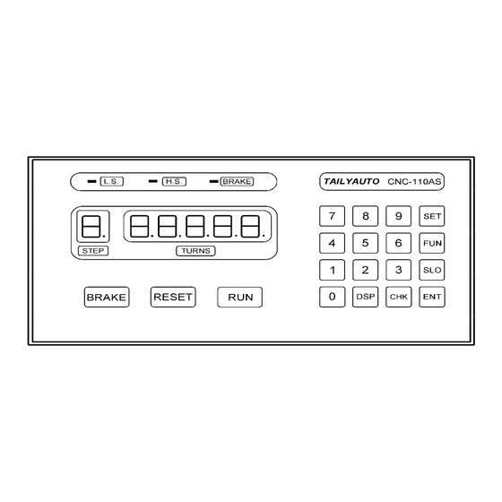
FRONT PANEL DESCRIPTION................................ 3
4.
MEMORY GROUP SELECTION ............................... 4
5.
WINDING PARAMETERS SETTING ........................ 4
6.
CONFIGURATION SETTING .................................... 5
7.
WINDING EXECUTION............................................. 7
8.
ADJUSTMENT .......................................................... 8
9.
FUNCTION TABLE ................................................... 9
10. INSTALLATION AND WIRING................................ 10
11. MAINTAIN AND TROUBLESHOOTING ................. 12
12. DIMENSIONS .......................................................... 15
CNC-110A Series
C-03/C-13 User's manual
(DOC NO:001212)
TAILY AUTOMATION CO.,LTD.
1
Advertisement
Table of Contents

Subscribe to Our Youtube Channel
Related Manuals for TAILY AUTOMATION CNC-110A Series

Summary of Contents for TAILY AUTOMATION CNC-110A Series
-
Page 1: Table Of Contents
CNC-110A Series C-03/C-13 User's manual (DOC NO:001212) INTRODUCTION ............2 MAIN FEATURES ............. 2 FRONT PANEL DESCRIPTION........ 3 MEMORY GROUP SELECTION ....... 4 WINDING PARAMETERS SETTING ......4 CONFIGURATION SETTING ........5 WINDING EXECUTION..........7 ADJUSTMENT ............8 FUNCTION TABLE ........... 9 10. -
Page 2: Introduction
AUTOMATION. It not only retains all the features of previous designs, it also has a low noise level and is less sensitive to external power fluctuation. CNC-110A series also features an integrated design: Putting DC motor speed controller, brake and power supplier control circuits into one control box, simultaneously achieving size reduction, high performance and low cost. -
Page 3: Front Panel Description
CNC-110A Series C-03/C-13 User's manual 3. FRONT PANEL DESCRIPTION 3.1.Key pads : 10 key, for entering numerical values. : Enter into PARAMETER SETTING mode. : During READY mode , to get into the function select mode. While setting SLOW STOP TURNS it used to select the winding direction. -
Page 4: Memory Group Selection
CNC-110A Series C-03/C-13 User's manual 4. MEMORY GROUP SELECTION The controller has three groups of memory. To selection the memory group is as follow. After specifying the group, setting and winding can be done in this group, all un-selected group will retain their original contents and unmodified. -
Page 5: Configuration Setting
CNC-110A Series C-03/C-13 User's manual 6. CONFIGURATION SETTING CNC-110AS is a multi-purpose design, to meet various requirements; additional settings are configured to provide flexibility for additional applications. In the READY mode, pressing the following keys combination as (6.1. ~6.9.) all the parameters can be changed. - Page 6 CNC-110A Series C-03/C-13 User's manual 6.7. Slow start turns Some of coil winding require slow speed start up in the first couple turns, and then become high speed winding. In READY mode, press keys, to set the SLOW STOP TURNS. [Setting range 0.1~9.9 turns].
-
Page 7: Winding Execution
CNC-110A Series C-03/C-13 User's manual 7. WINDING EXECUTION While press the key or press the foot switch, the controller will follow the winding parameters and the functions select, to operate the winding process. And if you want to pause the winding... -
Page 8: Adjustment
CNC-110A Series C-03/C-13 User's manual 8. ADJUSTMENT 110AS-006E.sch DC Motor DC Amperes meter WINDING SPINDLE SHAFT DRIVER CONTROL MODE SELECT 1C 2C 110V 220V 220V 220V 110V 110V TAILY TAILY 110B-DVRID:XXXXXX 110A-EXDID:XXXXXX AUTO AUTO 110B-DVR 110A-EXD CNC-110AS STANDART MODEL CNC-110EXD EXTERNAL CONNECTION MODEL... -
Page 9: Function Table
CNC-110A Series C-03/C-13 User's manual MAX : Maximum winding speed. 1. Rotate H.S. and L.S. potentiometer on back panel, to the right end [H]. Then press key to start winding in high speed, and press key to change the TURNS DISPLAY shows winding speed (RPM). -
Page 10: Installation And Wiring
CNC-110A Series C-03/C-13 User's manual 10. INSTALLATION AND WIRING 10.1.Counting system assembly The counting disc and the turns counter CNTB-03B/03C must be assembly as below. COUNTING DISC ZEROING DISC (OPTION) WINDING SPINDLE Unit=mm ZEROING SENSOR COUNTING SENSORS CNTB-03B/03C The zeroing disc is not served with the controller. If you need a zero point for the winding spindle, you have to make a zeroing disc as below, and assemble it with counting disc as above. - Page 11 CNC-110A Series C-03/C-13 User's manual 10.2.External wiring diagram for CNC-110AS 110AS-001E.sch BRAKER (DC24V 12W] TURNS COUNTER CNTB-03B/CNTB-03C INTERNAL SPEED ADJUST H.S. L.S. FUSE POWER SW 10A 250V H.S. AC POWER L.S. EARTH WINDING SPINDLE SHAFT EXTERNAL SPEED ADJUST 0.5HP DC MOTOR (OPTION) 10.3.External wiring diagram for CNC-110AE...
-
Page 12: Maintain And Troubleshooting
CNC-110A Series C-03/C-13 User's manual 10.4.Internal wiring diagram for CNC-110AS 110AS-004E.sch L.S. H.S. VR 10K VR 10K 110A-PNL RY-BLY 110B-DVR TF-015B 110V 220V 240V 110A-CPU 110AS KEYBOARD 10.5.Internal wiring diagram for CNC-110AE 110AS-005E.sch L.S. H.S. VR 10K VR 10K 110A-PNL... - Page 13 CNC-110A Series C-03/C-13 User's manual 11.1.Requirement and Safety precautions 1. The controller should be operated in an environment that is protected from moisture, corrosive gases, or liquid, and free from airborne dust, metallic particles, and magnetic noise. 2. Make sure that the power source supplies the correct voltage and is capable of supplying the required current to the controllers.
- Page 14 CNC-110A Series C-03/C-13 User's manual 11.3.Troubleshooting This section provides information to guide the user in understanding different fault condition and their general troubleshooting procedures, and with their possible solutions. Fault Description Correctives Action Power ON, but the display a. Check AC power input.
-
Page 15: Dimensions
CNC-110A Series C-03/C-13 User's manual 12. DIMENSIONS 20.0 150.0 20.0 30.0 85.0 31.0 CNC-110AS/CNC-110AE 3.2 x 2 3.1 x 4 10.0 12.0 13.0 Counting Sensor Counting Disc CNTB-03B 3.1 x 4 Zeroing Disc TAILY AUTOMATION CO.,LTD.
Need help?
Do you have a question about the CNC-110A Series and is the answer not in the manual?
Questions and answers
請問圖片中的白鐵線控制器可以共用嗎?