
Subscribe to Our Youtube Channel
Related Manuals for Advanced ExGo Series

Summary of Contents for Advanced ExGo Series
- Page 1 Remote Status Indicators Installation and Commissioning The operation and functions described in this manual are available from Software Version Ex-3000-V2.05C onwards. www.advancedco.com...
- Page 2 Specifications: Item Specification Details Enclosure Steel IP30 Dimensions H x W x D mm 190 x 235 x 45 Class A – Indoor IP30 0°C to 40°C Environmental Class Humidity 95 % Max Weight (excluding batteries) 1.5Kg Cable Entries (20mm knockouts) 4x top and 4x bottom rear 24V DC Nominal (18V –...
-
Page 3: Table Of Contents
Table of Contents Page INTRODUCTION TANDARDS AUTIONS AND ARNINGS ESCRIPTION OPERATION NTRODUCTION 2.1.1 Front Panel Controls and Indications 2.1.1.1 Display 2.1.1.2 LED Indications 2.1.1.3 Manual Release Button (Ex-3030 Only) 2.1.1.4 Navigation Buttons 2.1.1.5 Key-Switches 2.1.1.6 Buzzer PERATING ONDITIONS 2.2.1 Fire Alarm Condition 2.2.2 Release / Activated Condition 2.2.3... -
Page 4: Introduction
1 Introduction 1.1 Standards The Ex-3000 Series of Gas Extinguishing Remote Status Indicating Panels conform to the following standards: BS EN60950: 2000 Safety of information technology equipment BS EN50130-4: 1996 Product Family Standard Electromagnetic Compatibility Directive 89/336/EEC (and the amending directive 92/23/EEC) Low Voltage Directive 73/23/EEC 1.2 Cautions and Warnings Only Trained service personnel should undertake the Installation,... -
Page 5: Operation
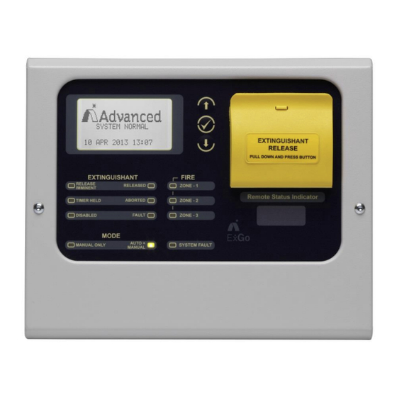
Operation 2.1 Introduction These instructions cover the operation and use of the panels. 2.1.1 Front Panel Controls and Indications Ex-3030 Manual Release Navigation Buttons Button E X T I N G U I S H A N T R E L E A S E P U L L D O W N A N D P R E S S B U T T O N E X T I N G U I S H A N T F I R E... -
Page 6: Led Indications
2.1.1.2 LED Indications The LED Status Indications show the basic operational state of the panel and whether the panel is in a fire alarm, fault, disabled or test condition. 2.1.1.2.1 GENERAL STATUS Function Colour Description Indicates the presence of a system fault SYSTEM FAULT Yellow 2.1.1.2.2 DETECTION ZONE STATUS... -
Page 7: Navigation Buttons
2.1.1.4 Navigation Buttons Press to scroll through the list of event conditions. Press to scroll through menu options. Press to display the menu and confirm selection of a menu option. Press to exit from a menu option. Press to MUTE panel buzzer (if configured). 2.1.1.5 Key-Switches One key-switch is fitted to the panel. -
Page 8: Operating Conditions
2.2 Operating Conditions 2.2.1 Fire Alarm Condition The display shows location / origin of the fire alarm and the total [Fire Detected] number of zones in a fire alarm condition. FIRE STARTED: ZONE 1 If two or more zones enter the fire alarm condition, the display also TOTAL FIRES: 1 shows the location of the last zone to enter a fire alarm condition. -
Page 9: Hold Condition
RELEASE ACTIVATED When the discharge is complete (either time elapsed or flow detected) the display indicates the discharge is complete. 00:00:10 Elapsed DISCHARGE COMPLETE (No Flow Detected) RELEASE ACTIVATED If confirmed by the detection of the flow of the extinguishant, the display shows RELEASE CONFIRMED (Released Condition) and 00:00:10 Elapsed the RELEASED LED turns ON steady. -
Page 10: Abort Condition
2.2.4 Abort Condition If an abort button is activated, the imminent release countdown is RELEASE ABORTED! aborted. The display prompts for the panel to be reset and the ABORTED PRESS RESET TO REARM LED is illuminated. Ensure that the abort button is de-activated and then press the RESET button. -
Page 11: Level 1 Menu Functions
2.3 Level 1 Menu Functions The following table gives a list of the Level 1 Menu Functions and a brief description for each function. Menu Option Sub Menu / Comments / Description Item VIEW FAULTS View any current fault conditions recorded. DISABLES View any current disablement conditions. -
Page 12: Disables
2.3.2.2 Disables [Disable List] If there are disablement conditions present, the display will show Zone 1 DISABLED the number of conditions and a list of the disablements. Man Release DISABLED Press the buttons to scroll through the list of disablements. Press the ... -
Page 13: Installation
3 Installation 3.1 Installation Approvals 3.1.1 Fire System Installations The panel must be installed and configured for operation in accordance with these instructions and the applicable code of practice or national standard regulations for fire systems / extinguishing system installation (for example BS5839-1: 2002, BS7273-1: 2006) appropriate to the country and location of the installation. -
Page 14: Installing The Back Box
3.3 Installing the back box Enclosure dimensions and fixing points are shown in the diagram below. Remove the chassis before installing the enclosure (retain in a safe place). Ensure that there is sufficient space to allow the cover to be removed / opened when the panel is finally mounted. -
Page 15: Wiring Installation
3.4 Wiring Installation To maintain electrical integrity of the SELV wiring on the The unit is designed for easy wiring installation. DC Power and Communications lines all SELV wiring “Plug-in” terminal blocks are provided for all should be segregated from LV mains wiring and be wired using cable with insulation suitable for the application. -
Page 16: Rs485 Communications
M O D E A U T O + S Y S T E M F A U L T M A N U A L O N L Y M A N U A L 3.4.1.3 RS485 Communications One RS485 bus circuit is provided for connection of the Remote Status Indicator panels to the U S B 4 8 5 - I N... -
Page 17: Key-Switch Installation
3.5 Key-Switch Installation E X T I N G U I S H A N T F I R E R E L E A S E R E L E A S E D Z O N E - 1 I M M I N E N T R e m o t e S t a t u s I n d i c a t o r T I M E R H E L D... - Page 18 This page is intentionally left blank. www.advancedco.com...
- Page 19 USER NOTES www.advancedco.com...
- Page 20 EN54-4: 1997 +A2 Power supply equipment for fire detection and fire alarm systems for buildings Ex-3001 Doc Number: 680-149 Revision: 03 Advanced Electronics Ltd Moorland Way, Cramlington, Northumberland, NE23 1WE UK Tel: +44 (0)1670 707 111 Fax: +44 (0)1670 707 222 Email: sales@advancedco.com...
Need help?
Do you have a question about the ExGo Series and is the answer not in the manual?
Questions and answers