Advertisement
Quick Links
NEBMM23G15EH...R3LEG14
Motor cable
Instructions | Assembly
8113243
2019-10a
[8113245]
Translation of the original instructions
© 2019 all rights reserved to Festo SE & Co. KG
1
Applicable documents
All available documents for the product è www.festo.com/pk.
2
Safety
2.1
Safety Instructions
–
Do not connect or disconnect plug connector when powered.
–
Only assemble the product on components that are in a condition to be safely
operated.
–
Assembly and installation should only be carried out by qualified personnel.
These personnel have electrical training or a relevant qualification.
2.2
Intended Use
Connection of the motor and encoder of the motor EMMT-AS to the servo drive
CMMT-AS.
3
Configuration
3.1
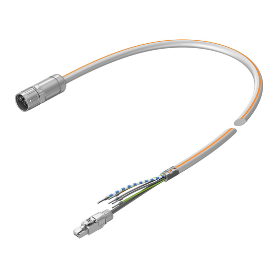
Product design
Fig. 1
3.2
Contact assignment
Electrical connection 1
Field device side
1 Socket
Pin
A
B
C
D
PE
1
2
3
4
5
6
7
8
9
10
1) Colour code in accordance with IEC 60757:1983-01
Tab. 1 Contact assignment
Festo SE & Co. KG
Ruiter Straße 82
73734 Esslingen
Germany
+49 711 347-0
www.festo.com
1 Socket M23x1, 15-pin
2 Plug connector RJ45
3 Wire ends (6x)
4 Cable
5 Screened connection
Allocation/
Electrical connection 2
Signal
Controller side
2 Plug con-
nector
Pin
U
–
V
–
W
–
Not assigned
–
PE
–
BR-
–
Not assigned
–
Not assigned
–
BR+
–
Up
7
OV
8
DATA+
4
DATA-
5
CLK+
1
CLK-
2
4
Mounting
4.1
Mounting of electrical connection 1
1. Align socket 1 to match plug.
2. Connect socket 1 to the plug.
3. Tighten the screw-type lock of the socket 1. Tightening torque:
1.2 Nm ± 10%
4.2
Mounting of electrical connection 2
1. Connect the wires in accordance with the contact assignment.
2. Align the plug 2 to match the socket.
3. Insert the plug 2 into the socket and click into place.
4.3
Strain relief for movable wiring
Electrical connection 1
NOTICE!
Movements of the cable can cause malfunction and material damage.
Push-in connector on the field device is damaged by transferred application of
force.
•
Ensure sufficient strain relief at a maximum 30 cm away from the socket.
8113243
Electrical connection 2
•
Fix the cable in the area of the screening connection 5.
Ä No force may be transferred to the cables.
4.4
Wiring
Character
istic
-E-
Tab. 2 Wiring
4.5
Mounting in energy chain
1. Lay the chain out lengthwise.
2. Place the cables in the chain, making sure they are not twisted.
3. Separate cables from each other using separators/drill holes.
4. Do not connect cables together.
Fig. 2
5. Maintain space X. X > 10 % of the cable diameter D.
If the chain is suspended vertically: increase the space X.
Fig. 3
6. Align chain in the operating position:
–
Make sure that the radius is greater than the bending radius R of the
cables.
3 Wire ends
–
Cables can move freely in the bending radius KR of the energy chain.
Wire colour
1)
Ä Cables are not forced through the chain.
7. Mount the energy chain è corresponding instructions.
8. Fasten cables:
BU
–
At both ends of the chain in case of short energy chains
BN
–
Only at the driver end in the case of long, sliding energy chains
BK
–
GNYE
BUWH
–
–
GNWH
Fig. 4
9. Do not bend cables all the way to the fastening point.
Ä Mounting space A between the fastening point and bending movement is
observed.
NOTICE!
Damage to cables if the chain breaks.
•
Replace cables after a chain break.
Cable characteristic
Wiring
Suitable for energy chains
In energy chain or flexible
Advertisement

Related Manuals for Festo NEBMM23G15EH R3LEG14 Series


Summary of Contents for Festo NEBMM23G15EH R3LEG14 Series
- Page 1 Ä No force may be transferred to the cables. Wiring Translation of the original instructions Character Cable characteristic Wiring © 2019 all rights reserved to Festo SE & Co. KG istic Suitable for energy chains In energy chain or flexible Applicable documents Tab. 2 Wiring Mounting in energy chain All available documents for the product è www.festo.com/pk.
- Page 2 NOTICE! Malfunction and material damage due to vertically suspended cables. The cables stretch. • Regularly check the length of the cables. • Readjust the cables if required. Technical Data NEBMM23G15EH... Q7... Q9... Q10... R3LEG14 R3LEG14 R3LEG14 Cable characteristic Suitable for energy chains Cable composition [mm²] 4x0.75 + 1x...