
Related Manuals for Electronics MagnaValve WM 3000-24

Summary of Contents for Electronics MagnaValve WM 3000-24
- Page 1 WM 3000-24 MagnaValve® Instruction Manual 56790 Magnetic Drive, Mishawaka, Indiana 46545 USA • 1-800-832-5653 or (574)256-5001 • www.electronics-inc.com IM0108 2018-08...
-
Page 2: Table Of Contents
AC-24 Controller Cable Connection ....................8 Troubleshooting ............................9 Maintenance ............................10 Spare Parts List ............................10 Contacting Electronics Inc.........................10 Limited Warranty ...........................11 Read this manual completely before installing the MagnaValve. WARNING! The MagnaValve emits magnetic fields and can be harmful to pacemaker wearers. -
Page 3: Product Overview And Principle Of Operation
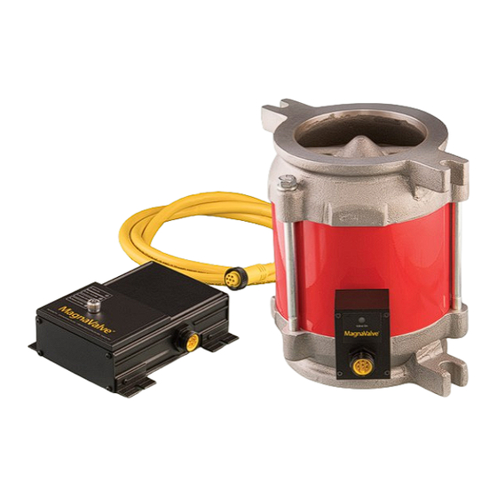
The MagnaValve is factory tested and results are supplied upon request. MagnaValve Controllers for Closed-Loop Operation For an “automatic” closed-loop operation, an Electronics Inc. AC-24 Controller will detect the current load on the wheel motor and regulate the flow of media to the WM 3000-24. -
Page 4: Installation
2) Enable Signal. The 24 Vdc Enable Signal is used to activate the valve. 3) Input Signal. The analog 0-10 Vdc input signal must be above 0.25 Vdc as a minimum flow command signal. AC-24 Controller Operation Please download the AC-24 Instruction Manual http://www.electronics-inc.com/data_sheets_and_instruction_manuals_for_wheel_blast_machine_products2.html... -
Page 5: Operation - Remote Valve Driver
Operation Remote Valve Driver lve Driver Panel (behind the cover plate) The large knurled screw on the front cover of the Remote Valve Driver can be removed to gain access to the factory adjustments. Please refer all adjustments to qualified personnel. è... -
Page 6: Specifications
Specifications MagnaValve Power +24 Vdc @ 2A (50 VA) Media Steel Shot and Grit Weight 32 lb (14.5 kg) Mode Normally Closed Temperature Range Valve: 50˚- 230˚ F (10˚-110˚ C) Signal Input 0 - 10 Vdc Flow Output 0 - 3,000 lb/min (0 - 1,361 kg/min)* Display LEDs Valve On 0 - 10 Vdc Command Input Available... -
Page 7: Dimensions
Dimensions 10.00” (254 mm) 9.00” .91” (229 mm) 7.13” 5.00” (23 mm) (181 mm) (127 mm) 9.30” 1.50” .56” (236 mm) (38 mm) (14 mm) 4.29” 4.50” (109 mm) (114 mm) 1.50” (38 mm) 2.87” (73 mm) For stability, the MagnaValve should be located as close as possible (within at least 3 ft / 1 m) to the blast machine wheel. 5.460”... -
Page 8: Remote Valve Drive Cable Connection
Remote Valve Driver Cable Connection The Remote Valve Driver should be installed in customer’s electrical panel. The 6-pin plug and cable wires connect to customer’s wiring per the following: White MagnaValve power signal - connect to valve driver, White only Green MagnaValve power signal - connect to valve driver, Green only Customer Power Supply in control panel - Power bus hot +24 Vdc... -
Page 9: Troubleshooting
If the problem can’t be identified or if you detect a problem with the magnetic field, contact Electronics Inc. Please have the following information ready. 1) Number of valves on the machine ___________________________________... -
Page 10: Maintenance
Electronics Inc. reserves the right to revise this publication and to make changes and improvements to the products described in this publication without the obligation of Electronics Inc. to notify any person or organization of such revisions,... -
Page 11: Limited Warranty
Limited Warranty The warranty obligations of Electronics Inc. for this product are limited to the terms set forth below. Length of Warranty Period This limited warranty lasts one (1) year from the shipping date of this product. What is Covered This limited warranty covers defects in materials and workmanship in this product. - Page 12 If this product is returned uninsured, Electronics Inc. does not assume any risk of loss or damage during shipment. Electronics Inc. will not be responsible for any costs related to the removal or re-installation of this product.
Need help?
Do you have a question about the MagnaValve WM 3000-24 and is the answer not in the manual?
Questions and answers