
Related Manuals for Addie Water Systems 6700

Summary of Contents for Addie Water Systems 6700
- Page 1 MODEL 6700 Downflow Brining Service Manual IMPORTANT: Fill in pertinent information on page 2 for future reference.
- Page 2 MODEL 6700 Downflow Job Specification Sheet Job Number _________________________________________________________ Model Number _______________________________________________________ Water Test___________________________________________________________ Capacity Of Unit _________________________ Max. ________________________ Per Regeneration Mineral Tank Size: Diameter____________ Height __________________________ Under Bedding _______________________ Amount _________________________ Type of Media ________________________ Cubic Feet_______________________ Brine Tank Size____________________________________...
- Page 3 MODEL 6700 Downflow General Residential Installation Check List WATER PRESSURE: A minimum of 25 pounds of water pressure is required for regeneration valve to operate effectively. ELECTRICAL FACILITIES: An uninterrupted alternating current (A/C) supply is required. Please make sure your voltage supply is compatible with your unit before installation.
- Page 4 MODEL 6700 Downflow Installation and Start-up Procedures (Cont’d.) Reserve Indicator: Time of Day Display Indicator Volume Remaining Above Reserve - Arrow Off Service Indicator: Volume Remaining At Or Below Reserve - Arrow Flashing Valve In Service - Arrow On Flow Indicator:...
- Page 5 MODEL 6700 Downflow Installation and Start-up Procedures (Cont’d.) 15. Manually initiate a regeneration cycle and allow water to run to drain for 3 to 4 minutes. Next, manually step the valve through a regeneration cycle checking valve operation in each step.
- Page 6 MODEL 6700 Downflow Control Operation Reserve Indicator: Time of Day Display Indicator Volume Remaining Above Reserve - Arrow Off Volume Remaining At Or Below Reserve - Arrow Flashing Service Indicator: Valve In Service - Arrow On Flow Indicator: Manual Regeneration Tonight - Flashing Arrow...
- Page 7 MODEL 6700 Downflow Control Operation (Cont’d.) Timeclock Regeneration Valves In Normal Operation the Time Of Day Display will be viewed at all times. The control will operate normally until the days since the last regeneration reaches the preset number of days. Once this occurs, a regeneration cycle will then be initiated immediately at the preset Regeneration Time.
- Page 8 MODEL 6700 Downflow Control Operation (Cont’d.) Control Operation During A Power Failure During a power failure all control displays will be turned off and regeneration cycles delayed. The control will otherwise continue to operate normally until line power is restored or battery backup power is lost.
- Page 9 MODEL 6700 Downflow Control Operation (Cont’d.) Control Operation During Programming The control will only enter the Program Mode with the valve in Service and operating on line power. While in the Program Mode the control will continue to operate normally monitoring water usage and keeping all displays up to date.
- Page 10 MODEL 6700 Downflow Water Conditioner Flow Diagrams (Downflow Brining) Using Black Cycle Cam (Part No. 17438) Service Position Backwash Position (Regeneration Cycle Step #1) Page 10 Printed in U.S.A.
- Page 11 MODEL 6700 Downflow Water Conditioner Flow Diagrams (Downflow Brining) Using Black Cycle Cam (Part No. 17438) (Cont’d.) Brine/Slow Rinse Position (Regeneration Cycle Step #2) Rapid Rinse Position (Regeneration Cycle Step #3) Page 11 Printed in U.S.A.
- Page 12 MODEL 6700 Downflow Water Conditioner Flow Diagrams (Downflow Brining) Using Black Cycle Cam (Part No. 17438) (Cont’d.) Brine Tank Fill Position (Regeneration Cycle Step #4) Service Position Page 12 Printed in U.S.A.
- Page 13 MODEL 6700 Downflow Downflow Valve Wiring Diagram Standard 6700 Wiring 6700 Wiring With Terminal Block Option Page 13 Printed in U.S.A.
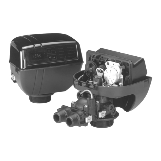
- Page 14 MODEL 6700 Downflow Valve Powerhead (See opposite page for parts list) Page 14 Printed in U.S.A.
- Page 15 MODEL 6700 Downflow Valve Powerhead Parts List Item No. Quantity Part No. Description 1 ... 1 ... 14193-03 ... . . Drive Panel 2 .
- Page 16 MODEL 6700 Downflow Control Valve Assembly - Downflow Brining (See opposite page for parts list) Page 16 Printed in U.S.A.
- Page 17 MODEL 6700 Downflow Control Valve Assembly - Downflow Brining Parts List Item No. Quantity Part No. Description *1 ... . 2 ... . . 13255 ....Adapter Clip 2 .
- Page 18 MODEL 6700 Downflow By-pass Valve Assembly, Brass Item No. Quantity Part No. Description 1 ... 1... . 17290....By-Pass Valve Body, 3/4″...
- Page 19 MODEL 6700 Downflow By-pass Valve Assembly, Plastic Item No. Quantity Part No. Description 1 ... 1 ... 19723 ....By-Pass Valve Body, Plastic 2 .
- Page 20 MODEL 6700 Downflow Meter Assembly (See opposite page for parts list) Page 20 Printed in U.S.A.
- Page 21 MODEL 6700 Downflow Meter Assembly Parts List Item No. Quantity Part No. Description 1 ... 1 ... 13821 ....Meter Body 2 .
- Page 22 MODEL 6700 Downflow 2310 Safety Brine Valve (See Opposite Page for Part List) Page 22 Printed in U.S.A.
- Page 23 MODEL 6700 Downflow Safety Brine Valve Parts List Item No. Quantity Part No. Description 1 ... 1 ... 19645 ....Safety Brine Valve Body 2 .
- Page 24 MODEL 6700 Downflow 2300 Safety Brine Valve Item No. Quantity Part No. Description 1 ... 1... . 60027-00 ... . . 2300 Safety Brine Valve body 2 .
- Page 25 MODEL 6700 Downflow Service Instructions A. TO REPLACE TIME BRINE VALVE, to the conditioner, and any by-pass line shut off. INJECTORS, AND SCREEN 11. Check for leaks at all seal areas. Check drain seal with the control in the backwash position.
- Page 26 MODEL 6700 Downflow Service Instructions (Cont’d.) 7. Place timer on top of valve. Be sure drive pin on 4. Remove two screws and clips at control valve. main gear engages slot in drive yoke. Pull meter module out of control valve.
- Page 27 MODEL 6700 Downflow Service Instructions (Cont’d.) PROBLEM CAUSE CORRECTION Softener fails to regenerate. A. Electrical service to unit has been A. Assure permanent electrical interrupted. service (check fuse, plug, pull chain or switch). B. Timer is not operating properly. B. Replace timer.
- Page 28 MODEL 6700 Downflow Service Instructions (Cont’d.) PROBLEM CAUSE CORRECTION Iron in conditioned water. A. Fouled resin bed. A. Check backwash, brine draw and brine tank fill. Increase frequency of regeneration. Increase back- wash time. B. Iron content exceeds B. Add iron removal from filter or recommended parameters.
- Page 29 1..17218..Piston, Downflow Rapid Rinse 60022-50 . . . BLFC .50 GPM 60125..6700 Seal and Spacer Kit 60022-100 . . BLFC 1.0 GPM For Illustration and Parts List,...
- Page 30 NOTES Page 30 Printed in U.S.A.
- Page 31 NOTES Page 31 Printed in U.S.A.
- Page 32 P/N 19085 Rev. 2 12/99 Printed 12/99...
Need help?
Do you have a question about the 6700 and is the answer not in the manual?
Questions and answers