Table of Contents
Advertisement
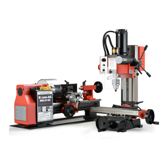
Mill Drill
BMMDL-07 +
Metal Lathe
BMLAT-05
User Manual
READ THIS MANUAL CAREFULLY BEFORE USE – FAILURE TO DO SO MAY RESULT IN INJURY, PROPERTY DAMAGE
AND MAY VOID WARRANTY. • KEEP THIS MANUAL FOR FUTURE REFERENCE. • Products covered by this manual may
vary in appearance, assembly, inclusions, specifications, description and packaging.
E&OE
© 2020 Baumr-AG
Advertisement
Table of Contents

Subscribe to Our Youtube Channel
Related Manuals for Baumr-AG BMMDL-07


Summary of Contents for Baumr-AG BMMDL-07
- Page 1 Mill Drill BMMDL-07 + Metal Lathe BMLAT-05 User Manual READ THIS MANUAL CAREFULLY BEFORE USE – FAILURE TO DO SO MAY RESULT IN INJURY, PROPERTY DAMAGE AND MAY VOID WARRANTY. • KEEP THIS MANUAL FOR FUTURE REFERENCE. • Products covered by this manual may vary in appearance, assembly, inclusions, specifications, description and packaging.
-
Page 2: Safety
• Use combustion engines OUTSIDE only, • If devices are provided for connecting dust and far away from windows, doors and extraction / collection facilities, ensure vents. these are connected and used properly. Dust collection can reduce dust-related hazards. E&OE © 2020 Baumr-AG... - Page 3 • Secure work. Use a clamp or a vise to hold down the work. Once it’s fixed securely, you can then use both hands to operate the machine. • Do not overreach. Always keep proper footing and balance. E&OE © 2020 Baumr-AG...
- Page 4 • Check for alignment and binding of all moving parts, broken parts or mounting fixtures and any other condition that may affect proper operation. Any part that is damaged should be properly repaired or replaced by a qualified technician. • Do not use the tool if any switch does not turn off and on properly. E&OE © 2020 Baumr-AG...
- Page 5 Cutting off the ground will result in a safety hazard and void the warranty. DO NOT MODIFY THE PLUG IN ANY WAY. IF YOU HAVE ANY DOUBT, CALL A QUALIFIED ELECTRICIAN. E&OE © 2020 Baumr-AG...
-
Page 6: Safety Symbols
Wear appropriate clothing Always wait for moving parts to injuries. fingers, limbs, blood etc. Take and protective devices. stop fully before handling the due care when handling and product, adjusting, maintenance using the product. etc. E&OE © 2020 Baumr-AG... - Page 7 Carry hook to load – do NOT Laser may be in use – do NOT Wear appropriate eye protection throw or run. for welding. Direct exposure to look directly at laser or allow weld arcs may cause permanent others to. eye injury. E&OE © 2020 Baumr-AG...
-
Page 8: Table Of Contents
Table of Contents Safety ................................. 2 Safety Symbols ................................6 Parts Identification – Mill Drill BMMDL-07 ..................... 10 External Features ..............................10 Longitudinal (Y) and Cross (X) Axis ......................... 11 Vertical (Z) Axis ................................ 12 Spindle and Gear Box............................... 13 Parts List ................................... - Page 9 Cross-Slide Feed Handle ............................41 Compound Slide Adjustments ..........................41 Accessories ............................. 42 External Jaws – 3-Jaw Chuck ..........................42 Fixed and Moving Steadies ............................43 How to Use a Thread Dial Indicator (Optional) ......................43 Specifications ............................45 E&OE © 2020 Baumr-AG...
-
Page 10: Parts Identification - Mill Drill Bmmdl-07
Parts Identification – Mill Drill BMMDL-07 External Features E&OE © 2020 Baumr-AG... -
Page 11: Longitudinal (Y) And Cross (X) Axis
Name Motor Base Fine feeding wheel Connecting strut Headstock & spindle Limit block Longitudinal feed hand wheel Controller Working table Balance mechanism Saddle Fuselage Cross feed hand wheel Electrical box Longitudinal (Y) and Cross (X) Axis E&OE © 2020 Baumr-AG... -
Page 12: Vertical (Z) Axis
Vertical (Z) Axis E&OE © 2020 Baumr-AG... -
Page 13: Spindle And Gear Box
Spindle and Gear Box E&OE © 2020 Baumr-AG... -
Page 14: Parts List
Cap screw M6 x 25 NutM6 Spindle box seat Handle Wedge Screw M6x 10 Limit block Guide finger Wedge Screw M6x 8 Ruler X-axis wedge Fuselage Saddle Electric box Y-axis wedge Lock nut M24 X-axis screw nut Big washer E&OE © 2020 Baumr-AG... - Page 15 PC board Ball ø 5.0 Lock sleeve Handle seat Rotor shaft Double head bolt MS x 70 Key 4 x 6 Knob Spring support Warning label Torsion spring Controller Cover Label on controller Shaft (1) Prop E&OE © 2020 Baumr-AG...
- Page 16 Supporting shank Internal ring ø 12 Screw Spacing ring Washer Small shaft Internal ring 12 Spacing ring Cover Spindle nut Top Cover Double round head key 5x5x30 Screw M3 x 6 Cap screw M5 x 8 E&OE © 2020 Baumr-AG...
-
Page 17: Installation
Run the Longitudinal Axis (Working table), Cross Axis (Saddle seat) and Vertical Axis (Fuselage) to ensure they’re in normal condition. • Be aware always while operating the machine. If you notice anything unusual, immediately stop using the machine and have it repaired immediately. E&OE © 2020 Baumr-AG... -
Page 18: Installation And Removal Of The Taper Shank
1. Loosen the handle (a) beside the limit block (b). 2. Adjust the limit block (b) into the desired position. 3. Tighten the handle. 4. Travel position can refer to the ruler on the fuselage rotary. E&OE © 2020 Baumr-AG... -
Page 19: Adjusting The Tip Angle Of The Fuselage
6. Adjust the middle portion first and then go towards the interior from two sides uniformly while you are adjusting the screw to ensure a uniformed pressure setting. E&OE © 2020 Baumr-AG... -
Page 20: Operation
6. Run for at least 2 minutes at this speed before stopping the machine and disconnecting it from the mains supply. 7. Ensure that all components are still secure and are working freely and correctly. 8. Ensure that all mountings are secure. E&OE © 2020 Baumr-AG... -
Page 21: Starting Under Normal Conditions
7. Turn the hand wheel of the working table (Y-axis) and the saddle seat (X-axis) to perform face milling. 8. Finishing all the steps, turn the power OFF and take the spindle back to the upper position, then you can take out the workpiece. E&OE © 2020 Baumr-AG... -
Page 22: Drilling/Milling Speed
The vise and workpiece are not secured firmly. Protection and Maintenance • Perform frequent maintenance checks and record any unusual findings. • Ensure that the power is turned OFF before performing any maintenance work on the machine. E&OE © 2020 Baumr-AG... -
Page 23: Maintenance
Put the cutter and work piece (or chuck piece) in the right places before turning ON the machine. After turning on the machine, the cutter will get closer to the working piece and will start milling it. E&OE © 2020 Baumr-AG... -
Page 24: Accessories Maintenance
Fuselage sear and connecting strut surface Lubricating Grease • X-axis feeding screw (saddle seat) • Y-axis feeding screw (worktable) • Z-axis feeding gear rack (fuselage) After each work, clean the worktable and lubricate it with a little lubricant for protection. E&OE © 2020 Baumr-AG... -
Page 25: Specifications
220mm Max Y Axis Table Travel 100mm Max Z Axis without collet 180mm Spindle Taper MT #3 Throat 167mm Table Size 390x92mm Spindle Speed Low :0~1000 RPM; High: 0~2500 RPM Swing 324mm Spindle to Table 292mm E&OE © 2020 Baumr-AG... -
Page 26: Parts Identification - Mini Metal Lathe Bmlat-05
Thread Dial Indicator (Accessory) Variable Speed Control Knob Cross-Slide Automatic Feed Lever Forward/Off/Reverse Switch Compound Slide Cross-Slide Feed Handle Emergency Stop Switch Tailstock Centre Apron High/Low Speed Range Lever Tailstock Manual (Saddle) Feed Handle Leadscrew Fwd./Neutral/Reverse Lever E&OE © 2020 Baumr-AG... -
Page 27: Headstock
(13) may be used to move the tool by small amounts at right angles to the cross-slide, or the slide may be set at an angle to the cross-slide so that short tapers or bevels may be cut. This is described in greater detail under Bevel Cutting. E&OE © 2020 Baumr-AG... -
Page 28: Motor
Motor It is not recommended that you disassemble the motor. Brushes may be replaced as described under Maintenance. For all other servicing and repairs, please contact your dealer. E&OE © 2020 Baumr-AG... -
Page 29: Unpacking & Preparing For Use
You will notice that, for transit purposes, the cross-slide feed handle has been mounted in reverse. Remove it, by unscrewing the hex socket head screw, securing it, and mount it the correct way around. Then turn all feed handles to ensure they are free and move evenly and smoothly. E&OE © 2020 Baumr-AG... -
Page 30: Installation
Alternatively, if you do not wish for a permanent installation, you may secure the lathe to a 5/8" thick plywood board with a minimum recommended dimension of 800x300mm, the mounting holes being centralised on the board. When the lathe is in use, the board should be clamped to workbench using with 'G' clamps. E&OE © 2020 Baumr-AG... -
Page 31: Starting Procedure
If you always use the Forward-off-Reverse switch (C) to Stop and start the lathe, you will not cause a fault condition and it will be quicker to use. CAUTION! NEVER attempt to change the range from HIGH to LOW with the machine still running. E&OE © 2020 Baumr-AG... -
Page 32: Starting Under Normal Conditions
This includes changing from High to Low range. ALWAYS turn the machine OFF at the Forward/off/Reverse switch BEFORE attempting to change any settings or make any adjustments. This includes changing from High to Low range. E&OE © 2020 Baumr-AG... -
Page 33: Operation
Once zeroed, retract the cross-slide one complete turn, then move the saddle until the tool is a short distance from the right-hand edge of the Work. Wind in the cross-slide again one full turn until the zero marks again coincide. E&OE © 2020 Baumr-AG... -
Page 34: Simple Turning With Power Feed
22. Carefully observe the movement of the tool and as it approaches the mark on the surface, denoting the end of cut, pull the Auto Lever UP sharply and ensure it stays UP. If a degree of accuracy is required, it is recommended that you finish the cut by hand. E&OE © 2020 Baumr-AG... -
Page 35: Bevel Cutting
The taper, or bevel, is cut by setting the cross-slide appropriately then using the compound slide feed handle to advance the cutting tool in the direction of the arrow, as shown in Fig. 9. E&OE © 2020 Baumr-AG... -
Page 36: Screw Cutting
Reset the tool by winding IN the cross-slide the exact number of turns previously wound OUT and then continue to wind IN the to the desired depth of cut. 29. Repeat steps 4 and 5. Proceed in this manner until the thread is completed. E&OE © 2020 Baumr-AG... -
Page 37: Changing Gears For Screw Cutting
The chart below shows the thread sizes that may be cut using the gear configuration shown in the corresponding columns. NOTE: The factory setup for the lathe provides for normal turning using the power or auto feed, and the gear configuration is as follows: E&OE © 2020 Baumr-AG... -
Page 38: Gear Chart For Cutting Imperial Threads
To cut 12 TPI, use 40T in position A, 30T in position D, and any convenient gear in position B to connect A and D. 31. Ref. Fig. B To cut 13 TPI, use 40T in position A, 65T in position B, 60T in position C, 30T in position D. E&OE © 2020 Baumr-AG... -
Page 39: Gear Chart For Cutting Metric Threads
They may be mounted either way round. The number of teeth on each gear is clearly marked. Replace the securing screws, ensuring the flat washer bears up against the gear hub in each case. E&OE © 2020 Baumr-AG... -
Page 40: Maintenance
Always remove cutting tools, and store in a safe place. Motor Brushes The Motor brushes may be changed by unscrewing the caps, visible at the front and rear of the machine, beneath the Headstock, as shown in Fig. 11. E&OE © 2020 Baumr-AG... -
Page 41: Settings And Adjustments
'sloppiness' of action. Any maladjustments will have a serious effect on the quality of your work, as they will all be transferred to the tool tip. It is vital that there is as little movement of the tool as possible. E&OE © 2020 Baumr-AG... -
Page 42: Accessories
Place them as shown in Fig. 14, and assemble in the same order, clockwise in the slots in the chuck, turning the chuck key as you insert them. Close the jaws fully and check to ensure E&OE © 2020 Baumr-AG... -
Page 43: Fixed And Moving Steadies
7). As your line passes the mark on the body of the dial indicator, engage the auto lever sharply and thread cutting will commence. 54. As the tool approaches the end of the desired thread, DISENGAGE THE AUTO FEED LEVER. Do not switch the machine OFF. E&OE © 2020 Baumr-AG... - Page 44 2. 1.25mrn/T = 1, 3.5 1 – 8 3. 0.7mm/T, 1.75mrn/T = 1, 4.5 1, 3, 5, 7 4. 0.4mrn/T = 1, 3, 5, 7 1 – 8 5. 0.8mm/T = 1, 5 1, 3, 5, 7 IMPERIAL E&OE © 2020 Baumr-AG...
-
Page 45: Specifications
Spindle Bore Tailstock Taper Spindle Bore 20mm Cross Slide Travel 65mm Compound Slide Travel 55mm Metric Range of Threads 0.4-2.0mm (10 Thread Pitches) Chuck Diameter 80mm Inch Thread (T.P.I) 12-52TPI (18 Thread Pitches) Power Plug Australian Standard E&OE © 2020 Baumr-AG... - Page 46 ©2020 Baumr-AG. All rights reserved. No part of this document, including descriptive content, concepts, ideas, diagrams or images may be reproduced or transmitted in any form or by any means, electronic or mechanical, including photocopying, scanning or recording, or any information storage and retrieval system,...
Need help?
Do you have a question about the BMMDL-07 and is the answer not in the manual?
Questions and answers