Table of Contents
Advertisement
Quick Links
Advertisement
Table of Contents

Related Manuals for Vertiv Liebert SmartAisle2


Summary of Contents for Vertiv Liebert SmartAisle2
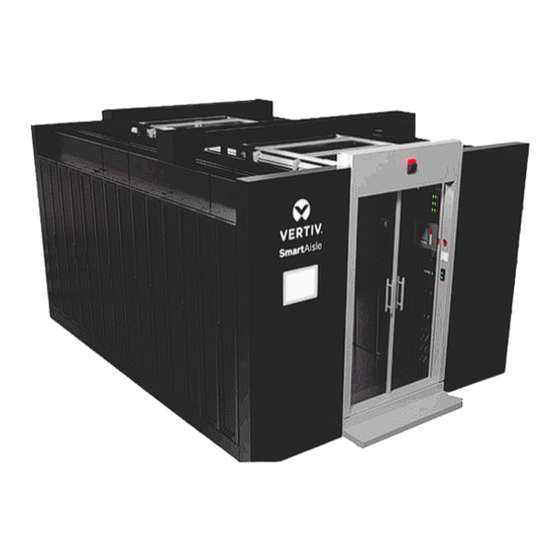
- Page 1 Liebert® SmartAisle2 User Manual...
- Page 2 Customer Service Hotline: 4008876510 India Email: customer.care@vertiv.com Customer Service Hotline: 8002096070 Asia Australia- au.service@vertiv.com New Zealand- au.service@vertiv.com Philippines- ph.service@vertiv.com Singapore- sg.service@vertiv.com Malaysia- my.service@vertiv.com For Technical Support, users may contact the nearest Vertiv Group Corp. local sales office or service center.
- Page 3 Styling used in the Guide The styles used in this manual are defined in the following table: Situation Description The Warning/Danger/Caution note indicates a hazardous or potentially harmful situation that can result in death or injury. It also indicates instructions that need to be adhered to, Warning/Danger/Caution failing which may result in danger and safety issues, thereby having an adverse effect on the reliability of the device and security.
- Page 4 Safety Precautions & Measures In this section, the safety measures related to the entire SmartAisle2 unit will be explained in detail. • Read the manual prior to installation and operation of the unit. Only qualified personnel should move, install, or service this equipment. •...
- Page 5 General Safety Instructions • Use the tools with an insulation handle. • Wear rubber gloves and safety shoes. • Avoid placing tools and metal objects on the battery surface. • Remove the watches, rings, or any metal objects. • Ensure the power is disconnected before operating any internal components of the product. •...
-
Page 6: Table Of Contents
2.4.2. Leveling the base ........................................23 2.4.3. Fixing the base .......................................... 24 2.4.4. Pre-conduit arrangement ....................................24 2.5. Cabinet Positioning ..........................................25 2.5.1. Removing the cabinet foot ..................................... 26 2.5.2. Cabinet base ..........................................26 2.5.3. Leveling the cabinet ......................................27 Vertiv | SmartAisle2 | User Manual... - Page 7 2.11. Installation of Lighting System ..................................91 2.11.1. Installing the Lighting Switch ................................91 2.11.2. Installing the Lighting Controller ..............................92 2.11.3. Lighting System Wiring .....................................93 2.12. Roof opening system installation ..................................95 2.12.1. Installation of roof opening button ..............................95 Vertiv | SmartAisle2 | User Manual...
- Page 8 2.14. Total System Power Input ......................................112 Chapter 3: Operation & Display Panel..........................113 3.1. Checks prior to Start ..........................................113 3.2. Power ................................................114 3.3. System Debugging ..........................................115 3.4. Shutdown ..............................................117 3.5. Display Panel Operations ......................................118 3.5.1. Data Modeling ..........................................118 Vertiv | SmartAisle2 | User Manual...
- Page 9 4.2. Main components of periodic maintenance & inspection table ..................126 4.3. Air Conditioning System Maintenance ..............................127 4.4. Breakdown and Disposal ...................................... 128 4.5. Troubleshooting ........................................... 128 Appendix I: Lighting Connector ....................129 Appendix II: Open Connection Diagram ................131 Vertiv | SmartAisle2 | User Manual...
-
Page 10: Chapter 1: Introduction
IT power consumption single module 92 kW Single refrigeration module 105 kW Overall key Altitude Less than 1000 m (air conditioning de-rating more than 1000 m) indicators Mounting Raised floor or ground installation Vertiv | SmartAisle2 | User Manual... -
Page 11: Salient Features
The integrated tricolor bright lights, set display, illumination and easy-to-understand interface to facilitate appropriate space lighting needs. • Human Machine Interface A 15-inch large control panel which is quite intuitive and advanced enables administrators and facility managers to visualize the entire system operation in real time. Vertiv | SmartAisle2 | User Manual... -
Page 12: Appearance And Components
Details of Equipment Base Server Cabinet Network Cabinet Access door Top Plate A/C Column Distribution Cabinet Strong wire passage groove Power cable trunking; copper and fiber cable tray Cabinet top wire groove Control panel Vertiv | SmartAisle2 | User Manual... - Page 13 Humidity, Water, and Leakage) equipment monitoring and control linkage. • Local display helps administrators or the concerned facility managers by presenting information to achieve the overall capacity, 2D and 3D temperature fields, alarms, and PUE to name a few. Vertiv | SmartAisle2 | User Manual...
-
Page 14: Environmental Requirements
1: For detailed installation techniques for the air conditioning and power distribution equipment along with the requirements, refer to the product’s user manual. 2: For the Air conditioning de-rating, contact the Vertiv local office; for the cryogenic components, contact your local Vertiv office or the local dealer. -
Page 15: Space
(spatial dimensions unit: mm). Figure 1-2 Interior Space side (Indoor) A plan view A side view (with the original base, the cabinet split foot) A side view (excluding the original base, the cabinet including feet) Vertiv | SmartAisle2 | User Manual... - Page 16 Vertical mounting space requirements (unit: mm) • Barrier free condenser outlet is 4000 mm. • Keep a space of 600 mm from the front and rear sides of the condenser for maintenance and repairs. Vertiv | SmartAisle2 | User Manual...
-
Page 17: Indoor Unit And Outdoor Unit Distance
Table 1-4, contact the Vertiv local office or office of the local dealer to ascertain the need for additional components to extend the pipeline and other measures. Table 1-4 Perpendicular to the indoor unit and outdoor unit level difference... - Page 18 2 pieces Base The base access door SA-SD121125 1 set Positioning the base member SA-SF121125 6 pieces Administration Kit SA-MP 1 set Administration Lighting Kit SA-LP12C 1 set Kit control panel SA-DP15 1 set Vertiv | SmartAisle2 | User Manual...
- Page 19 Several monitoring system Crystal Head RJ-45 Several Cable splicing Cable tie Several Tie line with 600 mm x 600 mm x 32 mm When there is a Static flooring 1 set calcium sulfate base Vertiv | SmartAisle2 | User Manual...
- Page 20 Rocker IRS-SA-LS Lighting cable set IRS-SA-LW The Kit control panel configuration is shown in Table 1-8. Table 1-8 Kit control panel Product name Product number Quantity Control panel IRS-SA-PN Screen control cable set IRS-SA-PW Vertiv | SmartAisle2 | User Manual...
- Page 21 This page is intentionally left blank. Vertiv | SmartAisle2 | User Manual...
-
Page 22: Chapter 2: Installation
Vertical projection, the level of the laser beam, vertical-horizontal adjustment device Drill Install the door frame on the ground Rubber hammer Structural parts mounting position fine adjustment tap Pliers Cutting the top plate rib hole modulus Ladder Equipment installation height Vertiv | SmartAisle2 | User Manual... -
Page 23: Equipment Handling, Unpacking, And Inspection
Installation 2.2. Equipment Handling, Unpacking, and Inspection Vertiv recommends rail or shipping for the product transportation. If road is the only option, choose less bumpy roads to prevent equipment damage. The size and weight of the package of each component is depicted in Table 2-2. - Page 24 While handling and unloading the equipment and cabinets, the center of gravity of the fork is to be taken into consideration to prevent dumping or equipment damage. Figure 2-3 Cross direction schematic view While moving the components, the obliquity should be maintained at an angle of 80° to 100°. Vertiv | SmartAisle2 | User Manual...
- Page 25 1. The product package assembly should be done on an open, solid horizontal surface. 2. During disassembly, open the carton belt with a knife. 3. Remove the device carefully. 4. Carefully, dismantle the film and packaging material on the product with a utility knife. Vertiv | SmartAisle2 | User Manual...
-
Page 26: Installation Precautions
Following is the assembly flowchart for the installation process: IT Cabinet Channel Bridge Base Installation Cabinet in Place Installation Installation Installation Power Monitoring the Room Open Lighting Refrigerant Distribution Installation Installation Installation Installation Installation Vertiv | SmartAisle2 | User Manual... - Page 27 Details of Equipment Base Server Cabinet Network Cabinet Access door Top Plate A/C Column Distribution Cabinet Strong wire passage groove Power cable trunking; copper and fiber cable tray Cabinet top wire groove Control panel Vertiv | SmartAisle2 | User Manual...
-
Page 28: Installation Of The Base
Control panel • The three parts connected and coupled in steps are the door susceptor by a channel base and the left and right channels of the base door as shown in Figure 2-5. Vertiv | SmartAisle2 | User Manual... - Page 29 Figure 2-6 shows the base assembly with a door fastener. Figure 2-6 Door assembly base • Base is mounted inside the channel floor support. Figure 2-7 shows the support member mounted within the floor channel. Vertiv | SmartAisle2 | User Manual...
- Page 30 • The cabinet base is connected to the base of the door pocket and the channel base of the cabinet is connected to the installed floor-side support member with the same base door as shown in Figure 2-8. Figure 2-8 Base connected to the base of the cabinet door Vertiv | SmartAisle2 | User Manual...
- Page 31 1200 mm. The base of the cabinet is connected to two rows of the stopper member as shown in Figure 2-10. Limit the equidistant positioning member mounted in the base assembly as much as possible on completion of the base assembly. Figure 2-10 Mounting channel width of the stopper member Vertiv | SmartAisle2 | User Manual...
-
Page 32: Leveling The Base
• Fasteners are not consequential around the base. 2.4.2. Leveling the base Figure 2-12 shows the removal of the outer base closure plate. Figure 2-12 Leveling the base of the closure plate to be torn Vertiv | SmartAisle2 | User Manual... -
Page 33: Fixing The Base
2.4.4. Pre-conduit arrangement The layout diagram of the indoor air conditioning unit is prearranged within the base line and ample length is allowed. Vertiv | SmartAisle2 | User Manual... -
Page 34: Cabinet Positioning
Power cable trunking; copper and fiber cable tray Cabinet top wire groove Control panel In this section, IT racks, air conditioning, power distribution, cabinet base, leveling, and cabinet fixing method will be explained in detail. Vertiv | SmartAisle2 | User Manual... -
Page 35: Removing The Cabinet Foot
Incline the cabinet to a specific angle and detach the four feet at the bottom and also remove the four dollars. • Vertiv recommends that the cabinet is placed in a step-like edge so that the pin is floating following which the cabinet can be disassembled without a steep angle inclination. -
Page 36: Leveling The Cabinet
• For SPM, air conditioner, and racks, refer to the respective user manuals for leveling procedures. • The cabinet must be leveled to meet the subsequent installation of a closed system; if not implemented and if quality issues occur, the customer is accountable. Vertiv | SmartAisle2 | User Manual... -
Page 37: Cabinet And Cabinet Connections
The accessories include a vertical cable management attachment plate, blind plates, trays, and windshield to name a few. Refer to the corresponding user manual on the cabinet accessories for more details. • For mounting the rack PDU, refer to the user manual of the IRS-P Series PDU. Vertiv | SmartAisle2 | User Manual... -
Page 38: Installation Of The Channel System
Power cable trunking; copper and fiber cable tray Cabinet top wire groove Control panel In this section, the roof installation will be explained in depth with the help of schematic diagrams to enable users to get grip with the procedure. Vertiv | SmartAisle2 | User Manual... - Page 39 L-shaped hexagonal wrench. This is to ensure that the stent plate is flushed with the cabinet frame. Figure 2-15 A schematic bracket mounting Figure 2-16 Notes bracket installation Vertiv | SmartAisle2 | User Manual...
- Page 40 2. The cabinet is connected with the support by a screw nut at three points. For a highly uniform stent enclosure, ensure that at least one spacer hole is mounted. Figure 2-17 Roof mounting bracket Vertiv | SmartAisle2 | User Manual...
- Page 41 • Limiting screw during the transport function provides a fixed rotation plate. Confirm that the four screws are removed prior to use. • The four screws that are removed can be utilized in the future. Vertiv | SmartAisle2 | User Manual...
- Page 42 • By timely fixing the screws, the position of the tab moves up thereby helping to avoid the influence of the rotation adjustment tab. Vertiv | SmartAisle2 | User Manual...
- Page 43 • Install the roof carefully to avoid severe injury to the personnel in case the roof falls. Vertiv | SmartAisle2 | User Manual...
-
Page 44: Installation Of Electric Gates
Details of Equipment Base Server Cabinet Network Cabinet Access door Top Plate A/C Column Distribution Cabinet Strong wire passage groove Power cable trunking; copper and fiber cable tray Cabinet top wire groove Control panel Vertiv | SmartAisle2 | User Manual... - Page 45 • An automatic door system comprises the various parts as described in Figure 2-23 and Vertiv recommends the installation of the aluminum groove member. Figure 2-23 Naming of parts in an automatic door system Vertiv | SmartAisle2 | User Manual...
- Page 46 Table 2-3 Automatic Door parts Part Name Icon Quantity Remark Motor Driven wheel Hanger device Belt fixture Double door belt fixture Leather belt Brake Power Supply Controller Safety light sensor Vertiv | SmartAisle2 | User Manual...
- Page 47 The front pillar on the outer end are first mounted on the left and right doors. The front cover housing the silver lintel needs to be removed. Figure 2-24 Removing the structural parts Vertiv | SmartAisle2 | User Manual...
- Page 48 Installation Figure 2-25 Remove door cover plate Figure 2-26 Removing the outer column Vertiv | SmartAisle2 | User Manual...
- Page 49 A top end surface of the inner side of the sunroof bracket is connected firmly by using at least three connecting surface mounting M6 bolts. Figure 2-28 Top of the door box is connected and fixed Vertiv | SmartAisle2 | User Manual...
- Page 50 • Cassette door frame and the door base connection screws (the screws of the cartridge frame are not the same regarding the floor). Therefore, this process must be done with utmost care and precision. Vertiv | SmartAisle2 | User Manual...
- Page 51 ST5 .5X22 from the rail to the frames. Both originate from the engine case during the installation process and uniform spacing of screws less than 400 mm is maintained while firmly mounting to the upper and lower rows. Figure 2-32 A schematic rail mounting Vertiv | SmartAisle2 | User Manual...
- Page 52 2-34. Connect the power cord and the power switch terminal based on the wiring diagram. Remove the mounting bolt of the power switch and connect the ground wire at the position shown in Figure 2-34. Figure 2-34 Mounting the power switch Vertiv | SmartAisle2 | User Manual...
- Page 53 Then, adjust the screw spacing with the controller installed on the screw. Adjust the distance between the controller and the motor to the position where the wires can be connected and tighten the mounting nut B. Vertiv | SmartAisle2 | User Manual...
- Page 54 50 mm from edge to edge. Before assembly, check if the doors are in a reliable and correct position. Check if the installation direction is correct; each hanger and glass door clamp connection should be done by using the door clamp hanging bolt. Vertiv | SmartAisle2 | User Manual...
- Page 55 • On unscrewing the suspension bolt, the glass door slider within the holder may slide out and fall. • Pay attention to the assembly direction of the hanger and the glass clamp; ensure that the bolt head of the glass clamp is positive.. Vertiv | SmartAisle2 | User Manual...
- Page 56 • Hanger assembly to ensure that there is minimum friction between the guide rails and the motion assembly. • Check for friction between the hanger assembly and the horizontal frame. • Check for friction between the door and the door frame. Vertiv | SmartAisle2 | User Manual...
- Page 57 (M6 X 12 with spring washers). It should be attached to the hanger assembly securely. Use a wrench and socket spanners to tighten the bolts. » The adjustment process is explained in the next section. » The 2nd door should be in closed position. Vertiv | SmartAisle2 | User Manual...
- Page 58 » Ensure that the bolts are firmly mounted using a wrench or socket wrench. » After adjusting the position of the door, the bolt B is screwed. Vertiv | SmartAisle2 | User Manual...
- Page 59 The driven wheel assembly is pulled to the left followed by tightening the fixing bolts. Turn the tension adjusting bolt in a clockwise direction to adjust the belt tension. • Adjust the gasket and the front of the board wherein they coincide as the most appropriate. Vertiv | SmartAisle2 | User Manual...
- Page 60 4 mm. Tighten the upper and lower adapter screw nut. Vertiv | SmartAisle2 | User Manual...
- Page 61 Installation Figure 2-47 Sensor door magnetic installation 1 Vertiv | SmartAisle2 | User Manual...
- Page 62 Installation Figure 2-48 Sensor door installation 2 Vertiv | SmartAisle2 | User Manual...
- Page 63 The inner and outer side of the glass has a pillar top columns; utmost care needs to be taken while installing the pillar tops to prevent it from falling off. Figure 2-49 Installing the outer column Vertiv | SmartAisle2 | User Manual...
- Page 64 • Do not err in the wiring order; else, a wrong connection will result in no action. • While installing the auxiliary light probe, prevent it from falling, collision, or external shocks as it leads to malfunction. Vertiv | SmartAisle2 | User Manual...
- Page 65 Ensure that the auxiliary light cable and door belt do not rub against each other. • The connection between the safety light transmitter and the receiver can not be reversed, otherwise the safety light will not work normally. Vertiv | SmartAisle2 | User Manual...
- Page 66 » Loosen the adapter nut in the F position and adjust the position of the F position before and after, so that the front and rear positions of the glass door are centered, and there is no obvious friction between the top and the top of the column. After the adjustment, tighten the nut. Vertiv | SmartAisle2 | User Manual...
-
Page 67: Installing The Mechanical Door
The Mechanical sliding door configuration comprises of a mechanical door, glass door (Pre-installed hanging clamp & magnetic stripe), door box, and the frame structure as configuration illustrated in Figure 2-55. Figure 2-55 Mechanical sliding door configuration 1 Vertiv | SmartAisle2 | User Manual... - Page 68 Semi-automatic door components are listed in Table 2-4. Table 2-4 Semi-automatic door components Part Name Icon Number (1 set) Door Closing Spring Tension lock plate Hydraulic retarder Gear wheels hanging Hanging round group Normally open sheet Vertiv | SmartAisle2 | User Manual...
- Page 69 Before the installation, remove the cover of the left and right door boxes and the front silver outer column; lintels also have to remove the cover. Figure 2-57 Remove the structural member Vertiv | SmartAisle2 | User Manual...
- Page 70 Installation Figure 2-58 Remove door cover Figure 2-59 Removing the outer column Figure 2-60 Remove the Lintel Cover Vertiv | SmartAisle2 | User Manual...
- Page 71 Figure 2-62 The bottom of the door box is connected and fixed 4. Lintel and the door frame connection frame: lintel and the door column are connected to the left and right sides by three M6x16 screws, a total of six. Vertiv | SmartAisle2 | User Manual...
- Page 72 • The door box frame and door base connection screws, and the door box frame and the floor screws are not the same, so utmost care must be taken with this installation point. Figure 2-64 End door frame mounted state of the cartridge Vertiv | SmartAisle2 | User Manual...
- Page 73 • The adjustment of both the tracks should be at the center position of the door while the two tracks should be kept at the same level; it should be in a horizontal position and the gap in docking must be less than 5 mm. Vertiv | SmartAisle2 | User Manual...
- Page 74 • Both the left door and right door along with the lifting gear are mounted on the left wheel set and the right hanging wheel assembly for each door; else it will result in erratic assembly. Vertiv | SmartAisle2 | User Manual...
- Page 75 • Is there any friction between the hanger stopper and the engine case? • Whether there is friction between the hanger device and the horizontal frame. • Is there any friction between the door leaf and the door frame? Vertiv | SmartAisle2 | User Manual...
- Page 76 Figure 2-71 Gear aligning the direction • Gear doors must be mounted in the direction respective to the requirements. If installed backwards the normal operation will not result in the proper closure of the door leaf. Vertiv | SmartAisle2 | User Manual...
- Page 77 • Slightly loosen screws to increase the wheel suspension; the tension of the rope is fixed to the screw collar hanging wheel. The contractible direction of the door is closed in the direction of the rope. Figure 2-72 Mounting tension Figure 2-73 Rally adjustment Figure 2-74 Schematic installation of the rally Vertiv | SmartAisle2 | User Manual...
- Page 78 • Mounting the back surface of the handle includes extending the handle into the stepped head of the screw mounting hole and locking the screw against the bottom of the stepped portion of the stepped screw. Vertiv | SmartAisle2 | User Manual...
- Page 79 • An outer vertical pillar screws (5 Nos.), which is about the same as the outer column fixation. The inner and outer side of the glass clip has paste on the pre-column tops. During installation, the pillar tops should be taken off to prevent it from falling over. Figure 2-77 Column installation Vertiv | SmartAisle2 | User Manual...
-
Page 80: Wind Shield Installation At The Bottom Without Dismantling The Feet
600 mm wide at the bottom spoiler (for 600 mm wide cabinet), and the bottom of the windshield which is 800 mm (pertaining to a 800 mm wide cabinet). Mount it in the same way as the bottom of the three types of the windshield. Vertiv | SmartAisle2 | User Manual... -
Page 81: Installation Of The Bridge System
Power cable trunking; copper and fiber cable tray Cabinet top wire groove Control panel The Bridge system installation comprises the IT racks entry holes, roof installation trunking, and the installation of the cross channel trunking. Vertiv | SmartAisle2 | User Manual... -
Page 82: Racks Entry Holes
Figure 2-80 Entry holes • A region of the reference trace cable Cat6 about 156, B Region the reference trace is about and the actual cables in the wiring process by floating at impact. Vertiv | SmartAisle2 | User Manual... -
Page 83: Roof Trunking Installation
The recommended installation position is from the front door to the rear door number with the fifth module hole as the starting point of the installation position; the recommended installation direction is the weak wire groove (wide wire groove end) close to the channel side. Figure 2-81 Recommended installation trunking Process Vertiv | SmartAisle2 | User Manual... - Page 84 • There are grounding screws in the four corners of the top line slot. Choose the grounding position based on the actual situation. The grounding screw size is M5. Figure 2-83 Trough ground point and fixed point Vertiv | SmartAisle2 | User Manual...
- Page 85 • The number of high-power channel reference routing is about 25 (3-core 6 square sheath cable); copper channel reference routing is about 300 (Cat6). The Fiber Channel reference routing is about 20. The actual amount of wiring affected by the wiring process will fluctuate. Vertiv | SmartAisle2 | User Manual...
-
Page 86: Cross-Channel Trunking Installation
Figure 2-86 The strength of electrical trunking cross-channel difference 1. Cross channel mounting channel – the cross channel is connected to the skylight roof by means of four M5X10 fixing screws. Vertiv | SmartAisle2 | User Manual... - Page 87 2. Mounting opening offline - Offline port is directly placed on the groove of the counter tops and connected to the roof duct with the position of the screws on the offline port is at the inner wall of the bent edge. Figure 2-88 Installation channel cross-channel (top) Vertiv | SmartAisle2 | User Manual...
-
Page 88: Installation Of The Air Conditioning System
In this section, the overall layout of refrigeration, air conditioning, and the mechanical installation method is explained in detail. • To ensure safety of the front-line of the repaired welding joints, the pressure release system in the air con- ditioning system should release clean nitrogen emissions. Vertiv | SmartAisle2 | User Manual... -
Page 89: Installation Of The Air Conditioning Pipes
• Initially, loosen the screw fixing the filter on the fixing piece. The fixing piece is removed on the filter and taken out in the same manner under the filter as shown in the following Figure 2-89. Figure 2-89 Air filters Vertiv | SmartAisle2 | User Manual... - Page 90 • High temperature by the water flow of the electrode humidifier and the heat resistance must be used over 90 °C pipes. • Consider security and IT equipment roof installation trunking, recommendation of underwater condensate drainage are explained in detail in the Liebert CRV + series of PACs. Vertiv | SmartAisle2 | User Manual...
- Page 91 Liebert CRV+ series of PACs user manual or contact the local Vertiv representative. • Refrigerant piping connections from the bottom of the unit are shown in Figure 2-92.
- Page 92 Adding the refrigerant will cause dilution of the refrigerant oil of the system. For lubricating and for cooling effects of refrigerant oil, add refrigerant oil. For a detailed procedure, refer to the user manual on the CRV+ series of PACs. Vertiv | SmartAisle2 | User Manual...
-
Page 93: Removal Transportation Fixtures, The Damping Material
Operation methods for doing so are listed in detail in the CRV+ series of PACs user manual. Vertiv | SmartAisle2 | User Manual... -
Page 94: Supply And Distribution System Installation
Power cable trunking; copper and fiber cable tray Cabinet top wire groove Control panel In this section, the general layout of the electrical distribution cabinet and a rear equipment mounting method is explained in detail. Vertiv | SmartAisle2 | User Manual... -
Page 95: Electrical Installation Air Conditioning
The full rated current of air conditioning is 46.6 A and the cable model must be selected accordingly. Figure 2-93 Electrical box and the user wiring diagram (opening the tailgate 120 °) Amplified (Left side) Vertiv | SmartAisle2 | User Manual... - Page 96 • The indoor unit and the outdoor section of the cable line connects the condenser with protective tubes or shielded wire. • The cable is not an object with high temperature (for example no brass pipe insulation, pipe, etc.) on con- tact. This prevents damaging the insulating layer. Vertiv | SmartAisle2 | User Manual...
- Page 97 • The indoor units start and stop signal lines lead directly to the condenser. • To prevent the infiltration of the water droplets along the electrical control box of the cable, all the user must wire the clamp and then lead it to the electrical box. Vertiv | SmartAisle2 | User Manual...
-
Page 98: Distribution Cabinet Electrical Installation
• Industrial male connector is mounted in a cabinet PDU cable termination • Industrial female connector is mounted at the output branch cable distribution cabinet ends. • Industrial male connector must be connected to the female plug. Vertiv | SmartAisle2 | User Manual... -
Page 99: Electrical Connection Of The Electric Gate
• If the power cord is incorrectly connected into the 220V AC terminal it will damage the electric gate and the warranty in this will get void and the customer is fully accountable for it. • PDU draws the Electric power from the cabinet door. Figure 2-98 Electric gate terminal block Vertiv | SmartAisle2 | User Manual... -
Page 100: Installation Of Lighting System
The lighting switch is mounted on the outer side of the right access door pillar. It has a rocker cover. Open the switch. The switch body is fixed upright with screws. Figure 2-99 Light switch installed • Ensure that the rocker switch plate is not upside down during mounting. Vertiv | SmartAisle2 | User Manual... -
Page 101: Installing The Lighting Controller
• If the lighting controller and the lighting switch are on the same side (on the side of the control box and not the cabinet roof), it will affect the connection. Vertiv | SmartAisle2 | User Manual... -
Page 102: Lighting System Wiring
Figure 2-102 Routing the wiring for the lighting controller and switch Lead the wiring to the lamp lighting controller as shown in Figure 2-103. The wire should be routed from the cable enclosure along the roof frame at the top of the row lines. Vertiv | SmartAisle2 | User Manual... - Page 103 Installation Figure 2-103 Route to a lighting controller lighting • PDU enclosure is supplied along with the lighting controller. • Route the cables accurately and in a firm, yet organized manner. Vertiv | SmartAisle2 | User Manual...
-
Page 104: Roof Opening System Installation
Screw the door sensor cable with the top plate fixing frame firmly fixed to the cross member, and the other side door is fixed to the rotary magnetic plate. Figure 2-105 Magnetic roof installation Vertiv | SmartAisle2 | User Manual... -
Page 105: Installation Of Top Open Controller
The screw helps in the connection between the control box and roof support. • Open the controller cooling holes facing in the outward direction. • Vertiv recommends to start from the first side of the top chassis and the button controller for opening should be mounted near the passage. -
Page 106: Installation Of Sound And Alarm Lights
• Sound and light alarm lamp are mounted on the lintel and not on the access door followed by complete module wiring. Finally, install the lintel casing. Figure 2-108 Sound and light warning light installation Vertiv | SmartAisle2 | User Manual... -
Page 107: Top Open Wiring
• The electromagnetic lock wiring is routed to the controller opening the top plate as shown in Figure 2-109. The cable is led across the cable enclosure along the roof frame at the top of the row lines. Vertiv | SmartAisle2 | User Manual... -
Page 108: Installation Of The Monitoring System
• Detailed installation requirements for RDU-A G2 can be referred to the user manual on RDU-A G2 wherein things are explained in great detail to enable users to get to grips with the installation process. Vertiv | SmartAisle2 | User Manual... -
Page 109: Installation Of Nvr & The Monitor Hard Disk
Details of Equipment Base Distribution Cabinet Server Cabinet Strong wire passage groove Network Cabinet Power cable trunking; copper and fiber cable tray Access door Cabinet top wire groove Control panel Top Plate A/C Column Vertiv | SmartAisle2 | User Manual... - Page 110 Figure 2-112 Control panel installation Vertiv | SmartAisle2 | User Manual...
-
Page 111: Install The Sensor
• 6 Nos. of standard temperature and humidity sensors are fitted uniformly on both sides of the inner channel in the cabinet. This is to ensure the accuracy of measurement of the temperature and humidity throughout the enclosed channel. Vertiv | SmartAisle2 | User Manual... - Page 112 • Water sensor mounting directions and instructions can be found in the IRM-S01W-belt type water sensor user manual. • Vertiv recommends the installation in the bottom of the air conditioning. • Flooding test strip connector should be pasted to the accompanying cable tie holder along with the detection lashing belt in a firm and organized manner.
- Page 113 Figure 2-116 Smoke installation • Remove the plug buckle for the passage of cable. • Excess cable line is drawn through the hole to minimize the improved aesthetics of the exposed cable. Vertiv | SmartAisle2 | User Manual...
- Page 114 Initially, with the base open, the cable passes through the cable hole through the lintel, and an infrared sensor is installed in the infrared base with screws while the infrared card which is mounted on the base, is connected with the network cable. Figure 2-118 Install infrared sensors Vertiv | SmartAisle2 | User Manual...
-
Page 115: Installation Of The Dome Camera
First, the plastic base and the cover hemisphere are removed, video cables and power cables are led to the base through the bracket and the lintel central hole over the line, the chassis with screws and the cover snaps into the plastic base. Figure 2-120 Installation hemisphere Bracket Vertiv | SmartAisle2 | User Manual... -
Page 116: Installation Of The Swipe Card Reader
• Each channel contains a door opening button inside and outside the mounting position. • Do not open the door button installed where an anti-finger sign is printed on the button which indicates an upward direction. Vertiv | SmartAisle2 | User Manual... -
Page 117: Wiring Card Reader/Door Opening Button
Figure 2-123 Brush wiring spreaders/door button 2.13.13. Monitor Connection Diagram RDU-A G2 Figure 2-124 RDU-A G2 monitor network connectivity Vertiv | SmartAisle2 | User Manual... - Page 118 IRM-S04D1 Phoenix smart digital sensor interface input user manual. • 4DI is set to the user mode meaning the sensor 6 bit DIP switch is ON. Control Panel Figure 2-125 Control Panel • Tighten the VGA cable to prevent loosening Vertiv | SmartAisle2 | User Manual...
- Page 119 Installation Access Controller Figure 2-126 Access Control Connections • Electric sides of the door channel can be accessed by a station controller. Vertiv | SmartAisle2 | User Manual...
- Page 120 Installation Electric door Figure 2-127 Electric Gate connection Vertiv | SmartAisle2 | User Manual...
-
Page 121: Total System Power Input
• Input line, Neutral, and Ground cables in the cabinet. • Fire-wire input is connected to the respective A-phase, B-Phase and C-phase input terminal. • Input, neutral, and ground wires are connected to the zero row in the cabinet and ground rows. Vertiv | SmartAisle2 | User Manual... -
Page 122: Chapter 3: Operation & Display Panel
Lighting controller power is properly connected Line resistance and no bump manual door Electric door Cable lashing rails in the firm, cannot be involved in the drive gears, belts Remove metallic debris from the rail Vertiv | SmartAisle2 | User Manual... -
Page 123: Power
5. Open the control panel power button to ascertain if normal operation is observed. 6. Open the power button RDU-M in the running state of the control system to check if normal operation is observed. Vertiv | SmartAisle2 | User Manual... -
Page 124: System Debugging
3-2. Figure 3-2 RDU-A G2 batch system configuration page 4. From the local computer to upload the files to the RDU-A G2, select the uploaded file type (for example, “Profile”). Click the Browse button. Vertiv | SmartAisle2 | User Manual... - Page 125 • Monitoring by the RDU-A G2 supervision platform of each device to confirm it is in an operational state. • The equipment must be functioning correctly before users can open servers and other IT equipment. Vertiv | SmartAisle2 | User Manual...
-
Page 126: Shutdown
5. Switch off the outdoor unit 6. Disconnect the power distribution cabinet input and branch output MCB open space. 7. Check and confirm that all the electrical equipment has been powered off completely. 8. Finally, close all the doors. Vertiv | SmartAisle2 | User Manual... -
Page 127: Display Panel Operations
In this section, various aspects related to the operations such as system capacity, temperature, alarm and PUE and their subsequent display on the Display panel will be explained in brief. 3.5.1. Data Modeling Figure 3-5 Data Modeling • Modeling methods are detailed in “RDU-M Room Management User’s Manual.” Vertiv | SmartAisle2 | User Manual... -
Page 128: Standard Basic Page
• Click the drop-down menu to hide the blank page. • To go back to the home page, click the Vertiv Icon. • The PUE dial displays the historical PUE Curve and is based on the aggregate information starting from five days prior to the current date. -
Page 129: Capacity Page
• On clicking the top of the rotary dial, the alarm arrow buttons and a 8 clockwise angle perspective is dis- played. • If the capacity display, other refrigerants, and the power distribution is displayed in black, it means there is no capacity information. Vertiv | SmartAisle2 | User Manual... -
Page 130: Wen Field Page
Figure 3-8 3D Temperature page Click on the Field temperature module to see temperature at the top, center, and bottom of the different rows of the cabinet. Vertiv | SmartAisle2 | User Manual... - Page 131 • The three temperature sensors in the distribution cabinet, rear door, and the intermediate position in the cabinet need to be configured. • The integrity and continuity of the temperature field, cooling, and temperature of the distribution cabinet can be configured. Vertiv | SmartAisle2 | User Manual...
-
Page 132: Alarm Page
• Green color indicates that there is no alarm. • If the refrigeration section and distribution section shows black, it means there is no alarm. • In case of a multi-level alert the most critical alarm color is displayed. Vertiv | SmartAisle2 | User Manual... -
Page 133: Pue Page
RDU-M user manual needs to be referred to for the same. • The PUE Curve is based on the data for the last seven days whereas the historical data for the last 30 days is shown. Vertiv | SmartAisle2 | User Manual... -
Page 134: Chapter 4: General Maintenance
• All trouble shooting is subjected to the manufacturers maintenance – otherwise the warranty is void. • Ignoring safety guidance can put the human life and environment at risk. • Inappropriate parts can lead to reduced performance or equipment downtime. Therefore, original components and recommended parts must be used. Vertiv | SmartAisle2 | User Manual... -
Page 135: Main Components Of Periodic Maintenance & Inspection Table
» Check the distribution cabinet for errors or faults. If the fault light is ON, there is a default alarm. » If the switch fails, contact the nearest Vertiv dealer or customer service for replacement or repair. • Additional details regarding the maintenance and replacement instructions can be obtained by referring to SPM user manual. -
Page 136: Air Conditioning System Maintenance
The inspection system water containing case (viewed through the sight glass) Inspection of the electronic expansion valve Check the operation of the heating element system Heating system Check by corrosion element • Refer to the CRV+ user manual for more general maintenance details. Vertiv | SmartAisle2 | User Manual... -
Page 137: Breakdown And Disposal
Ans: Ensure left door belt fixture fixed on top belt, right door belt fixture fixed on bottom belt, nothing blocks safe beam sensor. • General Troubleshooting for various components can be found in their respective user manuals, meaning air conditioning troubleshooting is available with the CRV+ series PAC manuals. Vertiv | SmartAisle2 | User Manual... -
Page 138: Appendix I: Lighting Connector
Lighting Connector Appendix I: Lighting Connector Vertiv | SmartAisle2 | User Manual... - Page 139 Lighting Connector Vertiv | SmartAisle2 | User Manual...
-
Page 140: Appendix Ii: Open Connection Diagram
Open Connection Diagram Appendix II: Open Connection Diagram Vertiv | SmartAisle2 | User Manual... - Page 141 © 2020 Vertiv Group Corp. All rights reserved. Vertiv™ and the Vertiv logo are trademarks or registered trademarks of Vertiv Group Corp. All other names and logos referred to are trade names, trademarks or registered trademarks of their respective owners. While every precaution has been taken to ensure accuracy and completeness here, Vertiv Group Corp.
Need help?
Do you have a question about the Liebert SmartAisle2 and is the answer not in the manual?
Questions and answers