Table of Contents
Advertisement
Advertisement
Table of Contents

Related Manuals for Vertiv SmartCabinet


Summary of Contents for Vertiv SmartCabinet
- Page 1 SmartCabinet™ User Manual...
- Page 2 Customer Service Hotline: 4008876510 India Email: customer.care@vertiv.com Customer Service Hotline: 8002096070 Asia Australia- au.service@vertiv.com New Zealand- au.service@vertiv.com Phillipines- ph.service@vertiv.com Singapore- sg.service@vertiv.com Malaysia- my.service@vertiv.com For Technical Support, users may contact the nearest Vertiv Co. local sales office or service center.
- Page 3 Styling used in the Guide The styles used in this manual are defined in the following table: Situation Description The Warning/Danger/Caution note indicates a hazardous or potentially harmful situation that can result in death or injury. It also indicates instructions that need to be adhered to, Warning/Danger/Caution failing which may result in danger and safety issues, thereby having an adverse effect on the reliability of the device and security.
- Page 4 Safety Precautions & Measures In this section, the safety measures related to the entire SmartCabinet™ unit will be explained in detail. • Read the manual prior to installation and operation of the unit. Only qualified personnel should move, install, or service this equipment.
- Page 5 Risk of Electric Shock There is a risk of an electric shock which may lead to personnel injury or death. To prevent or avoid such a situation, the following points must be taken into consideration: • Disconnect the control box and remote power supplies prior to working on the product. •...
-
Page 6: Table Of Contents
2.3.4.Installation of the 600mm wide Air conditioner with an integrated Condenser ......35 2.3.5.Connection of the Drain Pipe of the indoor unit ....................... 37 2.3.6.Installation of the Air Duct Parts (Optional) ........................38 2.3.7.Installation of the SmartCabinet Monitoring system ..................... 40 2.3.8.Cable Connections ....................................44 2.3.9.Configuration of the Communication Address and Port ..................49... - Page 7 4.2. Webpage of the MSC Intelligent monitoring unit ........................77 4.2.1.Login Preparation ...................................... 77 4.2.2.Login procedure for the MSC Intelligent Monitoring unit ................84 4.2.3.Home Page of the MSC intelligent Monitoring unit ....................86 4.2.4.MSC Card Menu Items ..................................91 4.2.4.1.Cabinet Data ......................................92 Vertiv | SmartCabinet | User Manual...
- Page 8 5.2.2.UPS & Power distribution servicing ............................136 5.2.3.Disassembly .........................................137 5.2.4. T roubleshooting .......................................137 5.2.5.FAQs for the MSC Intelligent monitoring card ......................139 Appendix I: System Distribution Diagram ...............143 Appendix II: System Wiring Diagram .................145 Appendix III: Hazardous Substances List ................147 Vertiv | SmartCabinet | User Manual...
- Page 9 Table of Contents This page is intentionally left blank. Vertiv | SmartCabinet | User Manual...
-
Page 10: Chapter 1: Introduction
Introduction Chapter 1: Introduction The SmartCabinet is an intelligent, integrated infrastructure solution from our Smart Solutions family for data centers. This streamlined offering provides fast and easy implementation, through interoperable systems, such as: precision cooling, UPS, power distribution/conditioning, and management software. The SmartCabinet uses a global design approach that can be localized for specific geographies. - Page 11 Incorporated with excellent monitoring-and-supervisory capabilities, the configuration-friendly SmartCabinet, developed with cutting-edge technology, is a turnkey solution that meets the requirement of potentially any ecosystem.
-
Page 12: Model Nomenclature
A: PDU 16 ports S: Separate B: PDU 24 ports A: Integrated 6: Width 600mm 1: 1 PDU 8: Width 800mm 2: 2 PDU 5: 5K UPS 8: 3K UPS Figure 1-1 Model Nomenclature Vertiv | SmartCabinet | User Manual... -
Page 13: Components
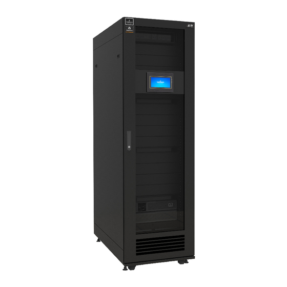
Introduction 1.2. Components The appearance of the SmartCabinet solution variants is depicted in Figure 1-2, Figure 1-3, and Figure 1-4: Figure 1-2 Appearance of the 600mm SmartCabinet solution Vertiv | SmartCabinet | User Manual... - Page 14 Introduction The appearance of the 800mm SmartCabinet solution is depicted in Figure 1-3: Figure 1-3 Appearance of the 800mm SmartCabinet solution Vertiv | SmartCabinet | User Manual...
- Page 15 Introduction The appearance of the 600mm SmartCabinet solution with the integrated condenser unit is depicted in Figure 1-4: Figure 1-4 600mm SmartCabinet solution with integrated condenser Vertiv | SmartCabinet | User Manual...
- Page 16 Introduction The major components of the SmartCabinet solution are listed in Table 1-1. Table 1-1 Major Components System Type Component Primary function Feature This component is used to store the 18U to 28U rack-mounted hardware equipment and complies The whole cabinet system is totally enclosed during...
- Page 17 Monitoring & and-play functionality of intelligent sensors from Management Vertiv; provides alarm notification of various kinds systems of devices and their environmental status; provides local display and control function for the user in LCD Display Local Display &...
-
Page 18: Ambient Requirements
Ensure that the installation field is levelled and Position SmartCabinet in this case. Equivalent horizontal space height is not less than 2300mm. distance between the indoor unit & outdoor unit of the AC: 20m; Vertical distance ∆H: -5m ≤ ∆H ≤... -
Page 19: Specifications
Introduction 1.4. Specifications The Specifications for the SmartCabinet can be viewed in the following Table 1-4. Table 1-4 Specifications of SmartCabinet Parameters Specification 600mm-wide Standard 80mm-wide Standard 600mm-wide Integrated Cabinet Cabinet unit Model MSC-XXS65XBXXXXX MSC-XXS85XBXXXXX MSC-XXI65XAXXXXX Dimensions (W*D*H, mm) 600*1200*2000... -
Page 20: Chapter 2: System Installation
• Prior to installation, some aspects need to be taken into consideration from the safety point of view. • The components of the SmartCabinet containment are large and heavy. Therefore, there may be a risk when the containment collapses. The collapse may result in physical injury, fatality, and damage to the equipment. - Page 21 Adjustable wrench Slotted screwdriver Cross head screwdriver Stepladder Forklift Drill Wire cutting pliers Claw hammer Diagonal cutting pliers Insulating shoes Antistatic gloves Electrician knife Cable ties Insulating tape Insulating gloves Crimping pliers Heat shrinkable tube Vertiv | SmartCabinet | User Manual...
- Page 22 Following are the steps to be followed for the installation of the floating nut: 1. Insert one fastener of the floating nut into the square hole of the vertical mounting rails, as shown in Figure 2-2. Vertiv | SmartCabinet | User Manual...
- Page 23 Figure 2-3. Figure 2-3 Schematic diagram 2 for installing floating nut Fittings The utilities used for fittings are shown in the following Figure 2-4. Vertiv | SmartCabinet | User Manual...
- Page 24 For the 600/800mm Standard Unit Sr. No. Product Name Quantity Note Cable Tie Cable Tie Fixture OT Terminal Floating Nuts, M6 30 (set) Accessory Box 1 Panel screw Floating Nut Hook MSC Intelligent 1 (set) Monitoring Card Hairbrush Vertiv | SmartCabinet | User Manual...
- Page 25 Self Prepared Materials The cables routed from the room to the SmartCabinet and the circuit breakers must be prepared at the customer site or are to be obtained by the customer; the specifications for the same are given in the Table 2-4.
-
Page 26: Transportation & Movement
Paper Box 2240 1416 <403 kg 800mm-wide component Standard Cabinet Wooden Box 2272 1416 <515 kg with 600mm-wide Paper Box 2260 1416 <374 kg package Cabinet with Integrated Wooden Box 2372 1416 <485 kg Condenser Vertiv | SmartCabinet | User Manual... - Page 27 The cabinet, closed frames, and the AC indoor unit need to be moved to the vicinity of the installation site. SmartCabinet, being an equipment with large components, is on the heavier side and needs to be transported using equipment such as a hand pallet truck or electric forklift.
- Page 28 While moving the package, the obliquity has to be maintained at an angle of 80-100°. Figure 2-9 depicts the 80° to 100° obliquity that is suitable to move the cabinet to the vicinity of the desired location. Figure 2-9 Carrying obliquity Vertiv | SmartCabinet | User Manual...
-
Page 29: Unpacking
2. Remove the feet pressure plate. • Remove the fixing screws on the pallet using a sleeve or movable wrench followed by removing the pressure plate as shown in Figure 2-10. Figure 2-10 Removing the Feet Pressure plate Vertiv | SmartCabinet | User Manual... - Page 30 • Slowly push the cabinet from the pallet along the slope down the ground. • Place the cabinet in the maintained position and adjust the feet fixing nuts till the cabinet gets into level. Figure 2-11 Removing the Pallet Vertiv | SmartCabinet | User Manual...
-
Page 31: Inspection
• If any parts or components are missing or damaged, immediately report to the carrier about the same. If hidden damages are observed, contact the local offices of that carrier as well as Vertiv Co. at the earliest. 2.2. Site Preparation SmartCabinet doesn’t need any specific site preparation as it’s an all-in-one enclosed system with excellent... - Page 32 Figure 2-12 Required clearance for opening the front and rear door (Top view, unit: mm) Following are the space requirements for the 600mm wide standard unit (Refer Figure 2-13): Figure 2-13 Space requirements of the 600mm wide standard unit Vertiv | SmartCabinet | User Manual...
- Page 33 Figure 2-14 Space requirements of the 800mm wide standard unit Following are the space requirements for the 600mm wide unit with the integrated condenser unit (Refer Figure 2-15): Figure 2-15 Space requirements of the 600mm wide integrated condenser unit Vertiv | SmartCabinet | User Manual...
-
Page 34: Weight Bearing Capacity
System Installation 2.2.3. Weight Bearing capacity The SmartCabinet solution is on the heavier side; therefore, the weight bearing capacity of the floor of the computer room must be taken into consideration. Refer to Table 1-6 under the Specifications section for the weights of the different models. However, during installation, the weight bearing capacity of the floor should also be estimated based on the total weight of the cabinet which also includes the installed equipment. -
Page 35: Installation Of The Cabinet
1. Place the cabinet in the prearranged position and use a movable wrench to loosen the fixing nuts on the 4-feet bolts on the cabinet. Figure 2-17 shows the procedure for the same. Figure 2-17 Loosening the fixing nut Vertiv | SmartCabinet | User Manual... -
Page 36: Installation Of The Ac Components For The 600Mm Standard Unit
Following are the steps that need to be observed while removing and placing the outdoor unit: 1. Remove the four screws on the press strips of the outdoor unit followed by removing the press strips as shown in Figure 2-18. Figure 2-18 Removing the press strips of outdoor unit Vertiv | SmartCabinet | User Manual... - Page 37 Figure 2-19 Removing the fixing screws of outdoor unit • Both top as well as the bottom piping methods are compatible with the SmartCabinet (for bottom pip- ing, loosen the connectors that connect the pre-installed pipes in the cabinet and the indoor unit).
- Page 38 Figure 2-20 The Outdoor unit is installed higher than the indoor unit Figure 2-21 shows the scenario where the outdoor unit is installed lower than the indoor unit: Figure 2-21 The Outdoor unit is installed lower than the indoor unit Vertiv | SmartCabinet | User Manual...
- Page 39 1. Lift the outdoor unit removed from the cabinet on to the top of the cabinet. Refer to Figure 2-23 for the installation direction of the AC outdoor unit. 2. Adjust the placement of the AC such that the AC foot is aligned with the corresponding screw holes on top of the cabinet. Vertiv | SmartCabinet | User Manual...
- Page 40 • Preferably, keep a distance of over 450mm between the outdoor unit and the wall, obstacles, or adjacent devices. • Avoid keeping the outdoor unit in places where snow may accumulate in the air intake side and air outlet side. Vertiv | SmartCabinet | User Manual...
-
Page 41: Connection Of The Copper Pipes
• The AC is an industry-grade device, used in the SmartCabinet system and is not sold separately meaning it is inclusive with the SmartCabinet package. Its total rated power is higher than 1 kW, in compliance with the IEC61000-3-2 standard. - Page 42 0.76 Installation Notes of the connector • Both top as well as the bottom piping methods are compatible with the SmartCabinet (for bottom piping, loosen the connectors that connect the pre-installed pipes in the cabinet and the indoor unit). • The connectors of the unit are located on the AC indoor unit and outdoor unit as well as on top of the cabinet.
- Page 43 1. The copper pipe provided by the factory is 5m in length. If longer pipes are required, contact the nearest Vertiv Co. office or the respective sales dealer. 2. The liquid pipe functions as the refrigerant liquid pipe of the outdoor unit outlet. So select an appropriate pipe diameter and length for the pipe to ensure that the pressure drop of the refrigerant liquid through the pipe during the unit operation doesn’t exceed 40kPa (5psi ~ 6psi).
-
Page 44: Installation Of The 600Mm Wide Air Conditioner With An Integrated Condenser
• The AC refrigerant used is R410A. Low quality or counterfeit refrigerant will cause severe damage to the system. Therefore, use the refrigerant recommended by Vertiv Co. Any damage or fault due to use of a low quality refrigerant or any other brand (other than the one recommended by Vertiv) will result in the warranty getting void. - Page 45 3. Turn the hex nut to the left to the maximum. Open the condenser valve till a significant resistance is felt. 4. The exposed copper tubes within the conditioned space is tightly wrapped in two layers of insulation material. 5. Once the machine is turned on, restore the cover to its original position. Vertiv | SmartCabinet | User Manual...
-
Page 46: Connection Of The Drain Pipe Of The Indoor Unit
• The drain pipe cannot be placed at frozen places or in freezing temperature. • It must be laid close to the ground. • The pipe must not be at higher level than the tray outlet. Figure 2-27 shows an example of condensate water pipe location: Vertiv | SmartCabinet | User Manual... -
Page 47: Installation Of The Air Duct Parts (Optional)
2.3.6. Installation of the Air Duct Parts (Optional) For the SmartCabinet with the integrated condenser, the heat inside the cabinet needs to be dissipated to the outside of the cabinet. If the dissipation of heat is not possible, a viable option is to install an air duct so that the hot air is sent outdoors similar to an exhaust air system. - Page 48 4. Post installation of the air duct parts, the air duct must be installed. The connection between the air duct and the cabinet is shown in Figure 2-30: Figure 2-30 Installation of the air duct Vertiv | SmartCabinet | User Manual...
-
Page 49: Installation Of The Smartcabinet Monitoring System
• The longest air duct supported by the system is 10m long with 2 elbow bends. If further extension in length is required (i.e. above 10m), contact the Vertiv Co. service department. 2.3.7. Installation of the SmartCabinet Monitoring system The following Table 2-11 shows the configuration of the SmartCabinet Monitoring system: Table 2-11 Product External... - Page 50 • Arrange the wires appropriately. Do not place any heavy objects on the wires or stamp on them. • The jumpers need to be set to the correct position. The jumper locations are shown in Figure 2-31. Vertiv | SmartCabinet | User Manual...
- Page 51 By default, the jumper setting of the MSC card is in the normal mode. The MSC card inserter is used to insert the card into the Intellislot intelligent card slot of the UPS. Once the card is inserted, tighten it by means of screws as shown in Figure 2-33. Vertiv | SmartCabinet | User Manual...
- Page 52 3. Connect the water leakage detective belt. 4. Lead and fasten the detective belt with the help of the provided cable tie fixture kits. 5. Place the detective belt at the bottom of the cabinet. Vertiv | SmartCabinet | User Manual...
-
Page 53: Cable Connections
• Bind the power cables and communication cables separately on the cable organizers on both sides in the rear space of the cabinet. Vertiv recommends that the power cables should be managed on the right cable organizer while the communication cables should be managed on the left cable organizer. - Page 54 System Installation Figure 2-35 shows the system wiring schematic diagram: Figure 2-35 Complete System Wiring diagram Vertiv | SmartCabinet | User Manual...
- Page 55 Also, consider the environment and refer to the global table as per the IEC60950-industry standard Table 3B. Vertiv recommends that the minimal CSA of selected cables must be 6mm2 and the external total input air breaker is large than or equal to 50A.
- Page 56 3. Lead the 485 control cable (2-core, insert-type) through the cable entry hole on the cover plate. Connect the cable to the corresponding terminal stud of the indoor unit based on the labels on the cable end. Figure 2-38 shows the connections for the preceding steps: Vertiv | SmartCabinet | User Manual...
- Page 57 M6 screw to fix one end of the earth cable to the earth hole. 2. Pass the other end through the rubber protective ring on the bottom plate to the earth copper bar of the computer room. Vertiv | SmartCabinet | User Manual...
-
Page 58: Configuration Of The Communication Address And Port
• While fixing the M6 screw on the earth hole of the cabinet, Vertiv recommends the use of a wrench. • If an earth block doesn’t exist in the building where the SmartCabinet is placed, use a yellow-green cable of no less than 6 mm²... -
Page 59: Cable Management & Installation Of Accessories
Figure 2-41 Cabling box of the 800mm wide standard unit – Installation area at the rear door Vertiv | SmartCabinet | User Manual... - Page 60 The cabling box can also be installed at the front door of the cabinet as shown in Figure 2-42. Figure 2-42 Box of the 800mm wide standard unit – Installation area at the front door • Vertiv recommends that the U height space, not occupied by the equipment, should be covered by the dummy panel.
- Page 61 This page is intentionally left blank. Vertiv | SmartCabinet | User Manual...
-
Page 62: Chapter 3: System Commissioning
System Commissioning Chapter 3: System Commissioning In this chapter, the operational instructions of SmartCabinet (including checks) before startup, and Power on/ Power Off procedures are explained in detail. System commissioning is a must before starting work on the machine. Therefore, the commissioning procedures are explained in depth to enable technicians to perform the startup process prior to any operation on the machine. -
Page 63: Inspection
• Before startup, confirm that the SPD module color is green. 3.3. Startup and Commissioning Prior to Startup of the SmartCabinet system, dial the service phone number (“400”) to authorize the startup of the UPS. The following flowchart (Refer Figure 3-2) depicts the startup steps to be taken while commissioning. - Page 64 5s. After self test, the UPS enters the bypass mode and the fault indicator turns on, and the buzzer beeps for 1s. 5. The rectifier startup is completed 30s after the rectifier enters the normal operation status, and then complete verifying the single unit parameter settings. Vertiv | SmartCabinet | User Manual...
-
Page 65: System Commissioning
• If an intelligent lock is selected, before opening it, confirm if the configured access control card can open the intelligent lock • The startup of the SmartCabinet system should be completed by authorized professionals. Vertiv rec- ommends an authorized personnel to carry out the Commissioning process. - Page 66 3. Choose the respective configuration options based on the equipment connections as shown in Figure 3-5: Figure 3-5 Setting and Configuration function 4. On selecting the corresponding configuration, the countdown begins following which the SmartCabinet system will restart and the configuration will be upgraded.
- Page 67 Intelligent Lock Commissioning (For specific models only) 1. The SmartCabinet system has an intelligent lock which supports both the key as well as the ID card. The key can be used to open the lock at any time; therefore, the key must be kept in a secure condition.
- Page 68 5 seconds, the lock will be locked automatically. 4. Authorization of the access control card can be carried out by the following steps: » Access the SmartCabinet webpage and click on the Home Page. Click Safe Management > Door Access as shown in Figure 3-8.
- Page 69 LCD will display a message stating that the card is invalid. » Go to the SmartCabinet webpage. Click Home Page > Safe Management. » Click on Door Access and choose the tab next to Door Authorization, i.e. History Events.
-
Page 70: Power Off
5. Open the UPS input and output air breakers. 6. Open the total air input breaker on the PMU. 7. Confirm If all the equipment is powered off. 8. Close all the doors of the cabinet. This sums up the commissioning process. Vertiv | SmartCabinet | User Manual... - Page 71 This page is intentionally left blank. Vertiv | SmartCabinet | User Manual...
-
Page 72: Chapter 4: System Operation
In this section, the LCD operation and the various menu options will be explained in detail in order to enable users get to grips with the functioning of the LCD panel. Figure 4-1 shows the SmartCabinet homepage. Figure 4-1 SmartCabinet homepage... -
Page 73: Thermal Management
In the following sections, the different options of the LCD HMI are explained in detail. 4.1.1. Thermal Management Click the Thermal icon on the display screen next to the Home button to access the Thermal Management screen (Refer Figure 4-3): Thermal Icon Figure 4-3 Thermal Management Vertiv | SmartCabinet | User Manual... - Page 74 • On entering the valid password, the settings screen is accessible wherein the AC power can be switched On or Off by means of a radio button. Also, the temperature can be set as per the requirement. Vertiv | SmartCabinet | User Manual...
- Page 75 Figure 4-5 Settings for Thermal Management • On modifying the settings, the confirmation dialog box is displayed where the user can save the modified settings as shown in Figure 4-6. Figure 4-6 Save Settings dialog box Vertiv | SmartCabinet | User Manual...
-
Page 76: Power & Distribution
• In the preceding example, there are 2 PDUs by default. Each screen under PDU2 will have the same display format as PDU1 Figure 4-8 PDU menu For PDU 1, There are three tabs, namely – Sampling, Control, and Setting. Vertiv | SmartCabinet | User Manual... - Page 77 Branch are active. The screen will prompt for a password for providing access to the Control screen for the PDU. Control Tab for Power Icon PDU1 Figure 4-10 Control Tab for PDU1 (Needs password) Vertiv | SmartCabinet | User Manual...
-
Page 78: Environment Management
Figure 4-12 shows the Environmental Management screen where the Sampling and Settings buttons can be viewed. Also visible are the icons for Alarm status of the Front and Rear door along with the alarm status of the Water logging sensor. Vertiv | SmartCabinet | User Manual... - Page 79 Figure 4-12 Environment Management • Click on the Settings icon to access the settings and the following screen displaying the various settings are displayed as shown in Figure 4-13. Setting Icon Figure 4-13 Environment Settings Vertiv | SmartCabinet | User Manual...
-
Page 80: Log Management
• Consider the alarm sound is off. If a new alarm occurs in this situation, the alarm sound will be turned off after 10 seconds. • However, if the backlight is off when the new alarm occurs, the alarm sound will be turned off after 5 seconds. Vertiv | SmartCabinet | User Manual... - Page 81 System Operation Figure 4-15 Active Alarm screen The History alarm screen will show all the historical alarms. Figure 4-16 shows the History alarm screen. Figure 4-16 History alarm screen Vertiv | SmartCabinet | User Manual...
-
Page 82: Settings
System Operation Figure 4-17 shows the Control log screen. Figure 4-17 Control Log screen 4.1.5. Settings Click Setting icon to display the Settings screen. Setting icon Figure 4-18 Settings icon Vertiv | SmartCabinet | User Manual... -
Page 83: 1.Language
• Network • System • Configuration 4.1.5.1. Language The Language button is used to switch between 2 built-in languages, namely- » Chinese » English Refer Figure 4-19 for Language Setting screen. Figure 4-19 Language Screen Vertiv | SmartCabinet | User Manual... -
Page 84: 2.Password
4.1.5.2. Password The Password function is used to change the password settings on the local LCD Screen. Incidentally, the password function can also be accessed using the web pages of the SmartCabinet unit (Refer Figure 4-20). Figure 4-20 Password Settings After entering the old and new password, click Save to store the updated password. - Page 85 There is a Maintenance mode option on the screen; if set to Yes, no alarm sound will be generated and the alarm icon changes to . To change that, the maintenance mode needs to be disabled. Figure 4-22 shows the System settings of the SmartCabinet unit. Figure 4-22 System Settings 4.1.5.5. Configuration The Config button on being selected shows the default configuration of the system, unless it has been changed (Refer Figure 4-23).
-
Page 86: Webpage Of The Msc Intelligent Monitoring Unit
• The recommended browser versions for the application are Internet Explorer (I.E.) version IE8, IE9, IE10, and IE11. Browser Settings The browser general settings, proxy settings, and the security settings are explained in detail. In this section to configure the web interface for accessibility. Vertiv | SmartCabinet | User Manual... - Page 87 » On clicking Settings, the following screen will pop up. Choose “Every time I visit the webpage” radio button under the “Check for newer versions of stored pages” as shown in Figure 4-25. Figure 4-25 IE General Settings » Click OK and the setting is saved. Vertiv | SmartCabinet | User Manual...
- Page 88 » Click the Connections tab in the Internet Options dialog box. Click LAN Settings (Refer Figure 4-26) Figure 4-26 Connections tab in IE Internet Options » On clicking LAN settings, the following dialog box opens up as shown in Figure 4-27: Figure 4-27 LAN settings dialog box Vertiv | SmartCabinet | User Manual...
- Page 89 Figure 4-28. » The following dialog box pops up and set the Reset to function under Reset custom settings to Medium-low and click on Reset (Refer Figure 4-29) » Click OK Vertiv | SmartCabinet | User Manual...
- Page 90 » Back to the Security Tab, Click on the Local intranet option next to the Trusted Sites option. Click on the Custom Level button. Refer to Figure 4-30 to see the illustration. Figure 4-30 Local Intranet settings Vertiv | SmartCabinet | User Manual...
- Page 91 » Similarly scroll up or down in the same window and set Enable for “Initialize and script ActiveX controls not marked as safe for scripting” as shown in Figure 4-32. Figure 4-32 Enable for “Initialize and script ActiveX controls not marked as safe for scripting Vertiv | SmartCabinet | User Manual...
- Page 92 » On clicking Sites, the screen shown in Figure 4-34 pops up, enter the IP address of the MSC card and click on Add. Figure 4-34 Adding the IP Address of the MSC card » Click Close. That sums up all the browser settings for the web interface of the MSC intelligent card. Vertiv | SmartCabinet | User Manual...
-
Page 93: Login Procedure For The Msc Intelligent Monitoring Unit
- Crystal blue » - Ocean blue » 3. If the ocean blue theme is selected, the screen color changes as shown in Figure 4-36: Figure 4-36 Ocean Blue theme Vertiv | SmartCabinet | User Manual... - Page 94 • The password can be retrieved only when the Email and SMS parameters have been configured on the SMS and Email Server Configuration page. The password received is a random temporary password and has to be modified after successful logging into the system. Vertiv | SmartCabinet | User Manual...
-
Page 95: Home Page Of The Msc Intelligent Monitoring Unit
If the high temperature fault has not been rectified for quite a long time, the technicians need to open the front and rear door of the cabinet; subsequently, contact the Vertiv customer support center for trouble- shooting of the issue. - Page 96 Figure 4-40 Setting button on the Home Page • Click on the Setting button and different status buttons will be displayed in place of the Setting button as shown in the highlighted red box in Figure 4-41. Figure 4-41 Setting status Vertiv | SmartCabinet | User Manual...
- Page 97 Figure 4-42 Selecting the Model Type for the Home Page • The Display settings can be set by clicking on the Set Display button. Click on Set Display and a dialog box pops up as shown in Figure 4-43. Figure 4-43 Display settings Vertiv | SmartCabinet | User Manual...
- Page 98 Time Calibrating Link The lower left part of the Home Page screen displays the System time of the SmartCabinet. Clicking the SmartCabinet time will direct the user to the time calibrating page. Refer to Figure 4-44 to see the Time calibrating link.
- Page 99 On clicking Logout, the screen will prompt for a confirmation in a dialog box as shown in Figure 4-48. Figure 4-48 Logout box Click OK following which the user will be logged out of the system. Vertiv | SmartCabinet | User Manual...
-
Page 100: Msc Card Menu Items
Refer to the following Figure 4-49 to see all the options mentioned in the list located at the right corner on the bottom of the webpage. Figure 4-49 Real-time Alarm Pop out settings 4.2.4. MSC Card Menu Items The Home Page contains the following menu items as shown in Figure 4-50: Figure 4-50 Menu Items Vertiv | SmartCabinet | User Manual... -
Page 101: 1.Cabinet Data
On clicking any device, the right side of the screen will get populated with information divided into 5 sections, namely- Overview, Sampling, Control, Setting, and Alarm. 4.2.4.1.1. Overview Click Edit button, the Overview screen is displayed as shown in Figure 4-52. Figure 4-52 Overview screen Vertiv | SmartCabinet | User Manual... - Page 102 Click Sampling tab, Figure 4-53 displays the screen showing the signals of the selected device. Figure 4-53 Sampling Signals If some signal is in alarm status, it will be displayed in red color. In Figure 4-53, the highlighted red box shows the Front door signal in red color. Vertiv | SmartCabinet | User Manual...
- Page 103 4.2.4.1.4. Setting Click Settings tab, Figure 4-55 displays the signal settings of the selected device. Figure 4-55 Signal settings A maximum of 16 signal settings can be configured at any given point of time. Vertiv | SmartCabinet | User Manual...
-
Page 104: 2.Ups Shutdown
Alarm levels of several alarm signals (a maximum of 16 signals) can be set at a given point of time. 4.2.4.2. UPS Shutdown Click UPS Shutdown menu to display two sub menus viz. Shutdown Schedule and Server Shutdown as shown in Figure 4-57. 4.2.4.2.1. Shutdown Schedule Figure 4-57 UPS Shutdown menu Vertiv | SmartCabinet | User Manual... - Page 105 Figure 4-59. Figure 4-59 Shutdown Mode format changing based on the chosen mode Figure 4-59 shows 3 different formats of the Shutdown mode, each while selecting Once, According to Day, and According to Week. Vertiv | SmartCabinet | User Manual...
-
Page 106: 3.Safe Management
3. Click Add button to add the Server Shutdown task for a specific server. • To use the Server Shutdown function, install the Vertiv Shutdown software in the server. 4. To delete a Server Shutdown task, Select the task to be deleted in the Server Shutdown task list and click the Delete button to complete the deletion of the task from the list. - Page 107 Figure 4-62 Fire Alarm Strategy 4.2.4.3.2. Door Access » Click the Door Access function under the Safe Management menu. This leads to access to the access control card management screen as shown in Figure 4-63. Vertiv | SmartCabinet | User Manual...
- Page 108 » Next is the History Events tab wherein event logs of the access control function can be viewed. Select the controller name and click on the Query button to gain information about the Door events. Alternatively, the results can be downloaded using the Download button as shown in Figure 4-65. Vertiv | SmartCabinet | User Manual...
-
Page 109: 4.Video Management
Enter the IP address, login user name and password, and HTTP port, HTTPS port and RTSP of the video equipment, click Test connection button to test if the video equipment has been successfully connected. Vertiv | SmartCabinet | User Manual... - Page 110 • Video management only supports IE browser. Figure 4-67 Internet install 4.2.4.4.2. Real-time video Click the Real-time Video tab under the Video Management menu to display the page shown in Figure 4-68. Table 4-1 gives an icon description. Vertiv | SmartCabinet | User Manual...
- Page 111 • After the capture and video operations, the file is saved in the save path of the Parameter settings\Lo- cal configuration\Corresponding operation. 4.2.4.4.3. Video playback Click the Video Playback tab under the Video Management menu. The page shown in Figure 4-69 is displayed. Table 4-2 gives the corresponding icon description. Vertiv | SmartCabinet | User Manual...
-
Page 112: 5.Alarm Management
Click the Alarm Management menu to display four sub-menus namely: Current Alarms, History Alarm, Alarm Notification, and Alarm Actions as shown in Figure 4-70. Vertiv | SmartCabinet | User Manual... - Page 113 Trigger value, Start Date/Time, Confirmed by, Confirmed on Date/Time, and End Date/Time columns along with their respective values. » Usr the Download button next to the Query button to download the Query results. Refer to Figure 4-71 to view the History Alarm menu: Vertiv | SmartCabinet | User Manual...
- Page 114 Customized Alarm Notification type such as Device Name, Alarm Description, Alarm Date/Time, Alarm Status, Alarm Level, etc..) » Click the Save button to complete the Alarm configuration. When the alarm is generated, the system will notify the users through the selected notification method. Vertiv | SmartCabinet | User Manual...
- Page 115 The communication parameter can also be set based on the requirement. Click on Save Configuration to store the current user’s SMS Modem configuration. • If the SMS Modem is connected via a USB port, modify the jumper locations as per the following Table 2-13. Vertiv | SmartCabinet | User Manual...
- Page 116 Configuration tab and choose the User, Notification by and Language Type field values. Set the Notification enabled period (Setting range 8:00 – 20:00), Notification Scheduled Cycle (Default: Hour), Interval of Notification (Default: 1), and Send Time Setting with the Start Time value. Click Save to store the settings. Vertiv | SmartCabinet | User Manual...
- Page 117 » If Signal is chosen for the Input and Output Parameters, choose the Device Register name, Signal Type, and Signal name from the dropdown menu. If Register is chosen, select the Device Register name from the dropdown menu such as R(0), R(1), etc… Vertiv | SmartCabinet | User Manual...
- Page 118 3. The input signal value of arithmetic operator GT/LT can only be float, int or long int; 4. All output signals can only be control signals, and the output signal value must be enumerated type. Vertiv | SmartCabinet | User Manual...
-
Page 119: 6.Data & History
Either ways, select the device type and click on the Download button to obtain the relevant information. Figure 4-79 shows an illustration of exporting the MIB information. Vertiv | SmartCabinet | User Manual... - Page 120 The result can be printed using the Print button. Even a Print Preview feature is present wherein the users can watch a preview of the historical curve graphs. Figure 4-81 displays the information in the Historical Curve format. Vertiv | SmartCabinet | User Manual...
- Page 121 Log Type followed by the Start/End Date and Time. Click on Query to obtain the log information. To download the Query results, click on the Download button. Figure 4-82 displays an illustration of the History log feature. Figure 4-82 Historical Logs Vertiv | SmartCabinet | User Manual...
-
Page 122: 7.Device Options
» Enter the Device address in its respective textbox. The Device address ranges from 1 to xx and under the same port, the device addresses must be unique. For some devices, there is no need to add a device address as the textbox is grayed out and cannot be edited. Vertiv | SmartCabinet | User Manual... - Page 123 » After rebooting, the user needs to log into the system again and the added device will appear in the list of equipment • SmartCabinet is to be configured using One Key via the Local LCD Screen. The Equipment added through the web interface of the MSC card cannot synchronize the data to the LCD screen •...
- Page 124 Save Configuration button is not clicked, a prompt message will be sent to the screen stating that confirmation is required to save the configuration. Following is the prompt message that pops up if you do not use the Save Configuration button. Figure 4-86 Save Configuration Message prompt Vertiv | SmartCabinet | User Manual...
- Page 125 » Click the Uninstall button next to the device under the Uninstall Device Type section. » A confirmation dialog box will pop up as shown in Figure 4-88. Figure 4-88 Confirmation Dialog Box for Uninstall Vertiv | SmartCabinet | User Manual...
- Page 126 Click the Asset Inventory tab and the following screen as shown in Figure 4-89 is displayed. Figure 4-89 Asset Inventory » The Asset Inventory page contains six items that can be set, namely- Equip Model, Equip Manufacturer, Equip Code, User Code, Power ON time, and Warranty Deadline. Vertiv | SmartCabinet | User Manual...
- Page 127 English letters, digits, space and underline. A prompt dialog box, stating that the characters are invalid, will pop up if any other characters are used as shown in Figure 4-91. Figure 4-91 Prompt dialog box stating use of invalid characters Vertiv | SmartCabinet | User Manual...
-
Page 128: 8.System Options
4.2.4.8. System Options Click System Options menu to reveal eight submenus, namely- Monitoring Unit, Network Setting, User Management, Date/Time Setting, Restore System, Site Setting, System Upgrade, and System Title. Figure 4-93 System Options Vertiv | SmartCabinet | User Manual... - Page 129 » The Blocked setting will be automatically cleared in 24 hours by default. 4.2.4.8.2. Network Setting The Network Setting submenu contains the following tabs, namely- Network Setting, Access Management, SNMP Configuration, Remote Service, and Security Setting. Figure 4-95 Network Setting Vertiv | SmartCabinet | User Manual...
- Page 130 After modifying the IP address, the system will adopt the new IP address settings by default. Use the new IP address to login again into the MSC intelligent monitoring system. Access Management The Access management is used to provide access to the RDU monitoring unit (Refer Figure 4-97) Vertiv | SmartCabinet | User Manual...
- Page 131 Figure 4-98 SNMP V2 setting » For SNMP V2, enter the NMS IP and set the Trap Level to Enable or Disable. » Keep the default values for other items. » Click on Add to add the NMS. Vertiv | SmartCabinet | User Manual...
- Page 132 » To make changes to the V3 settings, alter the values as per the requirement and click on Modify to store the changes. » To delete the record, select the NMS record and click on Delete to erase that specific NMS record. Vertiv | SmartCabinet | User Manual...
- Page 133 In Figure 4-101, the different fields of the Remote Service can be viewed. • Enter the customer name in the End-User textbox. • Choose the authority of the contact person such as admin, etc. Vertiv | SmartCabinet | User Manual...
- Page 134 » Choose the Web Server port from the options, i.e. Port 80 or Port 443. Click on Save. » Enable the Security policy, if required and enter the Account Valid period and the lock time in days and minutes respectively. Click on Save to store the security settings. Vertiv | SmartCabinet | User Manual...
- Page 135 • The user name may contain only English letters, digits, a Hyphen (-), or an underscore ( _ ). The Initial characters must only be English letters or digits. • The user levels are defined in the table under Table 4-3. Vertiv | SmartCabinet | User Manual...
- Page 136 Remember that the admin user can never be deleted as it is a super user administrator privilege. Modifying a user » Choose the user whose settings need to be modified. » Once the values gets populated, alter the values. » Click Modify. Vertiv | SmartCabinet | User Manual...
- Page 137 Local Host Time button following which the local date and time on the local machine will get populated. Click Set for the new settings to take effect. 4.2.4.8.5. Restore System Figure 4-105 shows the Restore System submenu under the System Options menu. Vertiv | SmartCabinet | User Manual...
- Page 138 System Operation Figure 4-105 Restore System » Click on Reboot SmartCabinet to reboot the system » Click on Restore System to restore all the default settings. » Click on Restore LCD Password to trigger the recovery of the password for the LCD screen.
- Page 139 » To restore the default Logo picture, click the Default button next to the Upload button. » Once all the information is entered, click OK for the settings to take effect. Refer Figure 4-108 to see the System Title configuration options: Vertiv | SmartCabinet | User Manual...
-
Page 140: 9.Help
Figure 4-108 System Title settings 4.2.4.9. Help Click Help Menu to reveal About SmartCabinet sub menu. Clicking on About SmartCabinet displays the Software Version, Serial Number, Identity Code, the user manual Download link, and the USB driver download utility link. - Page 141 This page is intentionally left blank. Vertiv | SmartCabinet | User Manual...
-
Page 142: Chapter 5: General Maintenance
• Unsuitable components will lead to hindrance in the performance of the equipment and even equipment shutdown. Therefore, Vertiv recommends the use of Vertiv OEM or Vertiv-approved components. 5.2. Maintenance of Main components In this section, the general maintenance of main components will be discussed. -
Page 143: 2.Indoor Unit Maintenance
Inspect the water pan periodically for normal operation of the drain pipe. Ensure that no foreign matter or leakage exists in the drain pipe. 5.2.1.3. Outdoor Unit maintenance The general steps for maintenance of the Refrigeration system, air cooled condenser, and compressor will be discussed in this section: Vertiv | SmartCabinet | User Manual... -
Page 144: 4.Maintenance Inspection Checklist
5.2.1.4. Maintenance Inspection checklist Periodic checks are essential to ensure proper operation of the AC unit. The following table in Table 5-1 is the maintenance inspection checklist for the AC unit: Vertiv | SmartCabinet | User Manual... -
Page 145: Ups & Power Distribution Servicing
The UPS fans are intended to run for 20000-40000 hours continuously. The higher the environmental temperature is, the shorter the fan life tends to be. Verify the fan status periodically on a half-yearly basis by checking if the airflow from the ventilation holes on the rear panel of the UPS is appropriate and is functioning normally. Vertiv | SmartCabinet | User Manual... -
Page 146: Disassembly
Use in overload the rated value Fan does not run normally Check whether the fan air breaker is closed Environmental high Call the customer service hotline of Vertiv: temperature alarm Fan is faulty 4008876510 The AC refrigeration output is Call the customer service hotline of Vertiv... - Page 147 Fan doesn’t run normally Check whether the fan MCB is closed Fan cannot start Fan is faulty Call the customer service hotline of Vertiv Remove debris from coil and air inlet; check the Insufficient condensing airflow fan speed controller for its speed regulation performance Check that the cable connections of the fan...
-
Page 148: Faqs For The Msc Intelligent Monitoring Card
Figure 5-1 Type CMD in the Run Box » Press the Enter Key and the Command Prompt page is displayed. Type Ping followed by the IP Address in the command line as shown in Figure 5-2. Vertiv | SmartCabinet | User Manual... - Page 149 Q5.> How to form a network of several SmartCabinets and perform centralized monitoring? A> The SmartCabinet supports connection to the RDU-M centralized monitoring platform of Vertiv Co. Check the networking mode of several SmartCabinets by referring to the following Network schematic...
- Page 150 General Maintenance Figure 5-3 SmartCabinet network topology diagram Q6.> How to restore the default settings of the MSC card? A> There are two ways of restoring the default settings of the MSC card, namely- 1. Software restore 2. Hardware restore...
- Page 151 Short pin 2 and pin 3 of the jumper J18 on the MSC card to complete the restoration process. The Jumper position is shown in Figure 5-4. Figure 5-4 Jumper locations of the MSC intelligent monitoring card Vertiv | SmartCabinet | User Manual...
-
Page 152: Appendix I: System Distribution Diagram
System Distribution Diagram Appendix I: System Distribution Diagram Silk printings of the PMU terminal block Vertiv | SmartCabinet | User Manual... - Page 153 This page is intentionally left blank. Vertiv | SmartCabinet | User Manual...
-
Page 154: Appendix Ii: System Wiring Diagram
Appendix II: System Wiring Diagram Vertiv | SmartCabinet | User Manual... - Page 155 This page is intentionally left blank. Vertiv | Liebert EXS 60kVA UPS | User Manual...
-
Page 156: Appendix Iii: Hazardous Substances List
Indicates the content of the toxic and hazardous substance in at least one of the average quality materials of the part is outside the limits specified in SJ/T-11363-2006. Vertiv Co., Ltd. has been committed to the design and manufacturing of environmentally-friendly products, it will reduce and eventually eliminate the hazardous substances in the products through unremitting efforts in research. - Page 157 Indicates the content of the toxic and hazardous substance in at least one of the average quality materials of the part is outside the limits specified in SJ/T-11363-2006. Vertiv Co., Ltd. has been committed to the design and manufacturing of environmentally-friendly products, it will reduce and eventually eliminate the hazardous substances in the products through unremitting efforts in research.
- Page 158 Indicates the content of the toxic and hazardous substance in at least one of the average quality materials of the part is outside the limits specified in SJ/T-11363-2006. Vertiv Co., Ltd. has been committed to the design and manufacturing of environmentally-friendly products, it will reduce and eventually eliminate the hazardous substances in the products through unremitting efforts in research.
- Page 159 Indicates the content of the toxic and hazardous substance in at least one of the average quality materials of the part is outside the limits specified in SJ/T-11363-2006. Vertiv Co., Ltd. has been committed to the design and manufacturing of environmentally-friendly products, it will reduce and eventually eliminate the hazardous substances in the products through unremitting efforts in research.
- Page 160 © 2019 Vertiv Co. All rights reserved. Vertiv and the Vertiv logo are trademarks or registered trademarks of Vertiv Co. All other names and logos referred to are trade names, trademarks, or registered trademarks of their respective owners. While every precaution has been taken to ensure accuracy and completeness herein.
Need help?
Do you have a question about the SmartCabinet and is the answer not in the manual?
Questions and answers