Advertisement
Quick Links
LOGICTECH
◈ We thank you for purchasing Logictech's product,Gyro LTG-2100T for EP
model Helicopter.
◈ Please read this manual carefully to the end in order for you to use
the product safely and for the best performance.
FEATURES
▶ High performance Smart Tail-Lock Gyro for EP model Helicopter which
succeed to the capability of LTG-6100T.
▶ Compensate the drift phenomenon of the tail which is influenced by
changing temperature.
▶ Automatic scan for Transmitter & Receiver types.(Logictech,Futaba,JR)
▶ Support dedicated Servo, standard Digital Servo and Analog Servo.
▶ Possible to set Servo Limit independently.(right and left)
▶ Remote controlled GAIN by Transmitter.
▶ Self diagnosis function.
▶ Ultralight design.
SPECIFICATIONS
▶ Operating Voltage
: 4.5 ~ 6v
▶ Power Consumption
: 20 mA
▶ Input Signal
: 2 Channels(Rudder, Gain)
▶ Output Signal
: 1 Channel(Servo Drive)
▶ Gain Control
: Remote control by transmitter
▶ Compatibility Mode
: Logictech,Futaba,JR system
▶ Data Setting Method : Button input and Stick operation
▶ Data Display Method : 8 Bit LED Display
▶ Dimension
: 22(W)mm x 22(H)mm x 11(D)mm
▶ Weight
: 10g
CAUTIONS
▶ Please be sure to use enclosed dedicated Tape when installing.
▶ Servo control is stopped in SETUP MODE. Please don't flying.
▶ Please refrain using in severe temperature condition.
(recommended temperature for using: -5℃ ~ 35℃)
▶ Recommend to use PCM type transmitter & receiver which has high
stability against a noise.
▶ Beginners should ask a help from where you can buy or expert.
▶ Please do not disassemble and remodel the product.
▶ Please stop the flight right away when you feel any malfunctions of
this product.
▶ Please use just defined voltage.
L
T
G
-
2
1
0
0
T
L
T
G
-
2
1
0
0
T
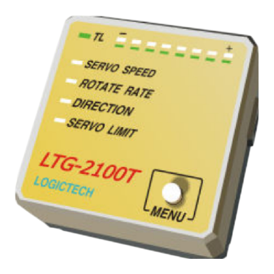
< NAME OF EACH PART >
④
※ Servo Control output
①
※ Rudd Signal input
※ Gain Signal input
③
②
① Operating Mode display LED (On: Tail-Lock, Off: Normal)
② Menu selection button (also used as Data input purpose)
③ Menu display LED for currently selecting.
④ GAIN display LED (display data in SETUP MODE)
SETUP PROCEDURE ( Please follow STEP 1 ~7 )
▶ Press the MENU BUTTON for 3 seconds over,then the SETUP MODE is enabled.
Whenever press button, Menu is moved to SERVO SPEED -> ROTATE RATE -> DIRECTION -> SERVO LIMIT.
▶ When Menu button is pressed in neutral status of RUDD Stick, Menu is moved to the next one. But in the status of stick holding to
right or left side, button pressing makes changing data related with current menu.
(Increasing or decreasing data is followed with stick holding direction)
STEP 1.
SELECTION RECEIVER TYPE
▶ This function is to memory by Auto-recognizing of Receiver Type for exact control characteristic.
▶ After recognition, it displays the receiver types which is in No.1-3 LED.(No.1: LOGICTECH, No.2:FUTABA, No.3: JR)
(RUDD Channel)
Reset all Trims which related
Pull Stick to the end of the left
in RUDD channel as zero
and turn on the power of Gyro.
Then wait for few second.
STEP 2.
SELECTION SERVO TYPE
▶ This function is to choose the kinds of Rudd Servos.(separate connector of servo before Setup)
▶ LED #1: D E D I C A T E D S E R V O
LED #2: S T A N D A R D D I G I T A L
▷ Press MENU button and select
SERVO
SPEED.
▷ After holding RUDD stick to the right or the left, press button and select Servo Type.
▷ Connect the servo connector separated.
High performance GYRO for EP model helicopter
< INSTALLATION >
① Please be sure united to Tape size and bottom size of GYRO.
② Please install the Gyro where is far distance from the electric
devices like motor.
③ Be sure to use just enclosed dedicated Tape.
④ Please do not allow to be touched on the body of Gyro from
Servo Wire or other things.
⑤ Please do not change the shape and the size of Tape.
(RUDD STICK)
After flashing LED 1~3 orderly and then
be off all, Turn back the RUDD stick to
the neutral quickly and wait.
LED #3: S T A N D A R D A N A L O G
TAPE
GYRO MOUNT on a heli
After auto scanning,
result is indicated to
one of the LED 1~3.
Advertisement

Related Manuals for Logictech LTG-2100T

Summary of Contents for Logictech LTG-2100T
- Page 1 ▶ This function is to memory by Auto-recognizing of Receiver Type for exact control characteristic. ▶ Gain Control : Remote control by transmitter ▶ After recognition, it displays the receiver types which is in No.1-3 LED.(No.1: LOGICTECH, No.2:FUTABA, No.3: JR) ▶ Compatibility Mode : Logictech,Futaba,JR system ▶...
- Page 2 ◈ SELF-DIAGNOSIS FUNCTION ▷ GAIN is displayed by 8pcs LED.(LED 1: 0%-30%, LED 2 : 31%-40%..LED 8: 91-100%) ▷ When powered on, LTG-2100T indicates the checked errors on the LED through self-diagnosis function. LED #1 flickering : error of Sensor STEP 4.
Need help?
Do you have a question about the LTG-2100T and is the answer not in the manual?
Questions and answers