Table of Contents
Advertisement
Quick Links
Advertisement
Table of Contents

Related Manuals for Alpha IP FAL 210 1 Series


Summary of Contents for Alpha IP FAL 210 1 Series
- Page 1 Alpha IP FAL 210x1-xx - 230 V FAL 410x1-xx - 24 V 132789.1629...
- Page 2 4,0 x 40 mm 1 x* 1 x* * FAL 410x1-xx HMIP-PSM Key: SGTIN:...
-
Page 3: Table Of Contents
7.4 Teach-off of the room control unit from a heating zone 7.5 Teach-in with Alpha IP Access Point 8 Configuration 8.1 Configuration with Alpha IP room control unit Display (S) 9 Displays 9.1 LED System key 9.2 LED Heating zones... -
Page 4: About These Instructions
2 Safety Intended use The Alpha IP base station is a component of the Alpha IP Systems and serves • for installation in environments of residential use, • for the arrangement of a room-by-room temperature control system with a maximum of 10 zones (depending on the type used) for heating and cooling systems, •... -
Page 5: Functions
3 Functions The Alpha IP base station serves for the room-by-room control of a floor heating system. The base sta- tion registers and processes the registered target and actual temperatures of connected Alpha IP room control units. -
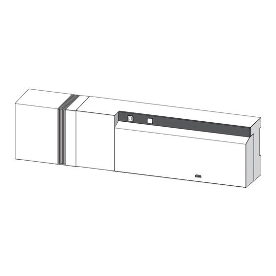
Page 6: Device Overview
Device overview 4 Device overview Indications and operating elements Relay HZ1 230 V ~ 3 (1) A Relay HZ2 - HZ10: 230V / 50Hz / 1A / max. 24W System key and LED Select key and LED Heating zones 1-10 (10-zone variant), or heating zones 1-6 (6-zone variant) Connections 24 V HZ1- HZ10: 24V 1A/HZ... -
Page 7: Technical Data
Device overview Technical data... -
Page 8: Installation
Installation 5 Installation DIN rail installation On-surface installation (only 230 V versions) 6 Connections Warning Danger to life due to the electrical voltage at the base station! • Only an authorised electrician may open the device. • Always disconnect from the mains network and secure against unintended activation before opening. •... -
Page 9: Opening The Housing
Connections Opening the housing Section 6.2 - 6.4 “Electric connection” Supply connection 24 V 230 V Relay HZ1 230 V ~ 3 (1) A Relay HZ2 HZ1- HZ10: 24V 1A/HZ Connection of actuators 24 V 230 V Relay HZ1 230 V ~ 3 (1) A Relay HZ2 - HZ1- HZ10: 24V 1A/HZ 24 V... -
Page 10: Activation/Deactivation Of The Pump Control (Base Station)
The connection terminal (G) can be used for the control of a recirculation pump. For this, set the heat- ing zone to pump control directly at the device as follows: 1. Press and hold the Select key (B) of the Alpha IP base station approximately for 4 seconds, until the LED of heating zone 1 flashes in green:... -
Page 11: Teach-In Without Alpha Ip Access Point (Stand-Alone Operation)
(HZx) (see section 7.1). Teach-in of the room control unit to several base stations For a teach-in of a room control unit to several Alpha IP base stations, the base stations must be cou- pled to each other first. -
Page 12: Teach-Off Of The Room Control Unit From A Heating Zone
3. Resetting the room control unit to factory settings (see manual of the respective room control unit). Teach-in with Alpha IP Access Point For a control via the Alpha IP app, the teach-on of the Alpha IP base station must be performed via the Access Point (HAP 21001). Teach-in the device as follows: 9 The Alpha IP Access Point has been set-up via the Alpha IP app (see manual HAP 21001). - Page 13 Configuration The configuration menu for the Alpha IP base station includes device parameters “UnP1/UnP2” and channel parameters “ChAn”, allowing to change lead and follow-up times for the pump, setback temper- atures, time intervals and many other parameters. The following table shows the available parameters:...
- Page 14 Configuration UnP2: Parameters Index Value Meaning Duration of valve pro- P007 0 minutes tection function 1 minute 133 (default) 5 minutes 10 minutes Time interval for valve P051 0 days protection function: 1 day 238 (default) 14 days 27 days 28 days ChAn: Parameters...
-
Page 15: Displays
Displays Parameters Index Value Meaning Time interval for pump P051 1 day protection function 2 days (only available Ch01) 238 (default) 14 days 27 days 28 days Cooling in cooling P052 inactive mode 1 (default) active Heating in heating P053 inactive mode 1 (default) -
Page 16: Cleaning
Cleaning 10 Cleaning Only use a dry and solvent-free, soft cloth for cleaning. 11 Resetting factory settings All settings will be lost when the factory settings are restored. 1. Keep the System key (A) pressed for 4 seconds, until it flashes rapidly in orange. 2. - Page 17 132789.1629...
Need help?
Do you have a question about the FAL 210 1 Series and is the answer not in the manual?
Questions and answers