Table of Contents
Advertisement
Advertisement
Table of Contents

Related Manuals for Spedo 2600

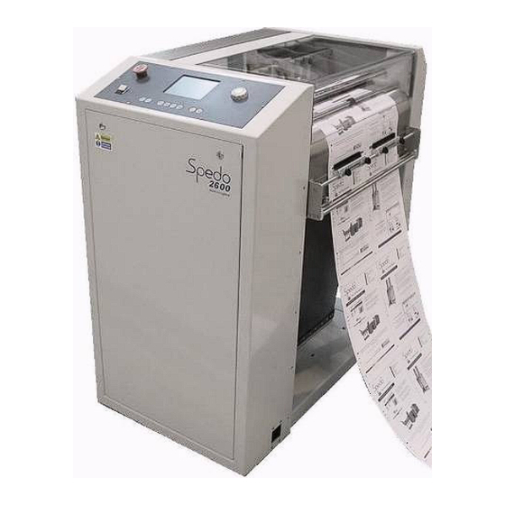
Summary of Contents for Spedo 2600
- Page 1 Issue 2 Part Number SP 007 011 76 Woolmer Way Bordon Hampshire GU35 9QF ENGLAND Telephone National: 01420 487442 International: +44 01420 487442 Facsimile National: 01420 477827 International: +44 01420 477827 1 - Spedo 2600 Service Manual SP 007 011...
-
Page 2: History Sheet
Spedo 2600 Forms Cutter History Sheet Manual Issue Date Changes Incorporated July 2012 First Edition January 2013 Change of Address 2 - Spedo 2600 Service Manual SP 007 011... -
Page 3: Copyright
No part of this publication may be reproduced, stored in a retrieval system, or transmitted, in any form or by any means, electronic, mechanical, photocopying, recording, or otherwise, without the prior written permission of Spedo UK Limited. Unpack Unpack the equipment and examine it thoroughly to ascertain whether any damage has occurred in transit. -
Page 4: Safety Measures
SAFE AND PROPER USE. Any adjustment, maintenance or repair of the opened apparatus under voltage shall be carried out only by a skilled person who is AWARE OF THE HAZARD INVOLVED. 4 - Spedo 2600 Service Manual SP 007 011... -
Page 5: Table Of Contents
Section 3f – Lower Blade Adjustment…………………………………………...28 Section 3g – Advanced Lower Blade Adjustment..........…...29 Section 3h – Upper Blade Adjustment…………………………………………...30 Section 4 – Drive and Pressure Head Units............36 Section 4a – Drive Wheel Assembly Removal………………………………...…36 5 - Spedo 2600 Service Manual SP 007 011... - Page 6 Section 7 – Trouble Shooting Guide ..............51 SCHEMATIC DIAGRAMS SP006 034 Operator Switch Assembly ............... 53 SP006 844 Control PCB – Internal I/O ............... 54 SP006 844 Control PCB – External I/O.............. 55 6 - Spedo 2600 Service Manual SP 007 011...
-
Page 7: Maintenance Procedures
The putting into operation of the machine, especially the actuation of the cross-cut forms cutter blade pre-supposes that the forms cutter has been correctly installed by a Spedo trained technician. The first time that the cross-cutting blade is to be actuated, it must only be carried out manually by a Spedo trained technician. -
Page 8: Maintenance Intervals
Operator Maintenance procedures This section must be completed by a competent operator or maintenance engineer Service Engineer's procedures This section must only be completed by a fully trained Spedo technician Section 1 – Edge Trimmer Units Section 2 – Centre Cutter Unit Section 3 –... -
Page 9: Operator Maintenance Procedures
WARNING The machine must be isolated from its power supply before starting any maintenance procedure. 1. Open the safety cover to gain access to the paper feed section. Using a vacuum cleaner to remove any build-up of dust. (Fig .1) 9 - Spedo 2600 Service SP 007 011... - Page 10 (Fig. 7) NOTE: Do not over oil the guide as this may cause marks on the end of the forms. 8. Remove the fan filter, (Fig. 8) and clean using a vacuum cleaner. WARNING Do not immerse the filter in water to clean. 10 - Spedo 2600 Service Manual SP 007 011...
-
Page 11: Section 1 - Edge Trimmer Units
5,000,000 cycle interval Please read this complete section before starting. WARNING The machine must be isolated from its power supply before starting any maintenance procedure Section 1a – Edge Trimmer Unit removal 11 - Spedo 2600 Service Manual SP 007 011... -
Page 12: Section 1B - Edge Trimmer Unit Strip
Failure to do so may result in the shaft becoming difficult to remove. (Fig. 8) WARNING Do not force the drive shaft in either direction. If the shaft is proving difficult to remove, examine the shaft for damage. Section 1b – Edge Trimmer Unit strip 12 - Spedo 2600 Service Manual SP 007 011... - Page 13 3. Loosen the grub screw in the front of the edge trimmer which retains the eccentric bush. (Fig. 5) WARNING The eccentric bush is spring loaded so you must keep your thumb over the top while removing the grub screw.(Fig. 6) 13 - Spedo 2600 Service Manual SP 007 011...
-
Page 14: Section 1C - Edge Trimmer Unit Rebuilt
9. Apply a small amount of light machine oil to the blade wick. (Fig. 13) 10. Remove any dust build up in the casting with a soft hair brush, or airline. (Fig. 14) Section 1c – Edge Trimmer Unit rebuild 14 - Spedo 2600 Service Manual SP 007 011... - Page 15 Section 1c – Edge Trimmer Unit rebuild (continued) 15 - Spedo 2600 Service Manual SP 007 011...
- Page 16 6. Apply HMP grease to the bearing surface of the lower hub. (Fig. 10) 7. Refit the lower hub and lower hub retainer. (Fig. 11 & 12) 8. Apply HMP grease to the upper hub axle. (Fig. 13) 16 - Spedo 2600 Service Manual SP 007 011...
-
Page 17: Section 2 - Centre Cutter Unit
WARNING The machine must be isolated from its power supply before starting any maintenance procedure. 1. Remove the lower centre cutter hub by completing Section 1a ‘Edge Trimmer Shaft Removal’ Section 2b – Centre cutter arm service 17 - Spedo 2600 Service Manual SP 007 011... - Page 18 Section 2b – Centre cutter arm service (continued) 18 - Spedo 2600 Service Manual SP 007 011...
-
Page 19: Section 2C - Centre Cutter Lower Hub Blade Change
9. Refit the centre cutter adjustment plate. If you haven’t changed any settings on the adjustment plate, then you will be able to simply refit, without further adjustment. (Fig 12) Section 2c – Centre cutter lower hub blade change 19 - Spedo 2600 Service Manual SP 007 011... -
Page 20: Section 2D - Centre Cutter Arm Adjustment
(Fig. 3). Tighten the top grub screw all the way in then loosen by ¼ turn. Then retighten the two marked grub screws. This will angle the blade as shown in Fig. 4. 20 - Spedo 2600 Service Manual SP 007 011... -
Page 21: Section 2E - Centre Cutter Setting
(Fig. 1) Tighten the hub in place. (Fig. 2) During this section I will be setting the centre cutter arm to cut on the right side of the lower centre cutter blade. This is our standard factory setting. 21 - Spedo 2600 Service Manual SP 007 011... -
Page 22: Section 3 - Cross Cut Blades
Arm Adjustment’. Section 3a – Cross cut blade guard removal Please read this complete section before starting. WARNING The machine must be isolated from its power supply before starting any maintenance procedure. 22 - Spedo 2600 Service Manual SP 007 011... -
Page 23: Section 3B - Cross Cut Blade Removal
6. Remove the service doors both ends. (Fig. 6) Section 3b – Cross cut blade removal WARNING The following sections involve handling extremely sharp blades. Protective gloves must be worn at all times. Extremely high risk of serious injury. 23 - Spedo 2600 Service Manual SP 007 011... -
Page 24: Section 3C - Blade Guide Preparation
6. Loosen the three nuts which hold the lower cross cut blade. (Fig. 8) The lower cross cut blade can now be lifted clear of the machine.(Fig. 9) WARNING Even blades that have been used may still be sharp so handle with care. 24 - Spedo 2600 Service Manual SP 007 011... - Page 25 Section 3c – Blade guide preparation 25 - Spedo 2600 Service Manual SP 007 011...
- Page 26 (Fig. 9) Then using a circular motion with a medium grade oil stone, hone the surface of the front blade guide. (Fig.10) If the surface of the blade guide is deeply scored then the part must be replaced. 26 - Spedo 2600 Service Manual SP 007 011...
-
Page 27: Section 3D - Lower Blade Preparation
5. Repeat step 3 & 4 until there are no burrs left on the blade. NOTE: Always finish on step 4. This means that any remaining burrs will be removed by the upper cross cut blade during operation. 27 - Spedo 2600 Service Manual SP 007 011... -
Page 28: Section 3E - Upper Blade Preparation
4. Repeat step 2 & 3 until there are no burrs left on the blade. NOTE: Always finish on step 3. This means that any remaining burrs will be removed by the lower cross cut blade during operation. Section 3f – Lower blade adjustment 28 - Spedo 2600 Service Manual SP 007 011... -
Page 29: Section 3G - Advanced Lower Blade Adjustment
Section 3g – Advanced lower blade adjustment This section shows how the lower cross cut blade is set in the factory. This level of accuracy is only necessary in certain applications. 29 - Spedo 2600 Service Manual SP 007 011... -
Page 30: Section 3H - Upper Blade Adjustment
(Fig. 6) NOTE: Be sure to re-check this measurement once the blade has been fully tightened. Section 3h – Upper blade adjustment 30 - Spedo 2600 Service Manual SP 007 011... - Page 31 Section 3h – Upper blade adjustment (continued) 31 - Spedo 2600 Service Manual SP 007 011...
- Page 32 Section 3h – Upper blade adjustment (continued) 32 - Spedo 2600 Service Manual SP 007 011...
- Page 33 1. Refit the upper cross cut blade. The blade should only be fitted loosely in position at this stage. (Fig. 1) 2. Loosen the blade backstop. And pull the stop away from the blade guide. (Fig. 2) 33 - Spedo 2600 Service Manual SP 007 011...
- Page 34 (Fig. 14) Also that the blade guide is correctly tensioned (Fig 15.) Place a torch as shown, (Fig. 16) this will help with setting the gap between the upper and lower blades. 34 - Spedo 2600 Service Manual SP 007 011...
- Page 35 21. Re-oil the blade wicks with a small amount of light machine oil, one drop down each oil channel. (Fig. 31) Also using light machine oil, apply one drop to the top of each blade mount block. (Fig. 32) 35 - Spedo 2600 Service Manual SP 007 011...
-
Page 36: Section 4 - Drive And Pressure Head Units
Section 4a – Drive wheel assembly removal Please read this complete section before starting. WARNING The machine must be isolated from its power supply before starting any maintenance procedure. 36 - Spedo 2600 Service Manual SP 007 011... -
Page 37: Section 4B - Drive Wheel Replacement
Section 4b – Drive wheel assembly replacement 1. Check the drive shaft for damage, paying particular attention to the key ways. (Fig. 1) Section 4b – Drive wheel assembly replacement (continued) 37 - Spedo 2600 Service Manual SP 007 011... -
Page 38: Section 4C - Drive Wheel Assembly Installation
(Fig. 1) When refitting the grub screws, (Fig. 2) apply a very small amount of medium strength retaining compound to the thread of each screw. (Loctite 243 or equivalent) Section 4d – Pressure head assembly removal Section 4d – Pressure head assembly removal (continued) 38 - Spedo 2600 Service Manual SP 007 011... -
Page 39: Section 4E - Pressure Head Assembly Strip
These screws have been highlighted with red paint (Fig. 2) Section 4e – Pressure head assembly strip Section 4e – Pressure head assembly strip (continued) 39 - Spedo 2600 Service Manual SP 007 011... - Page 40 6. With the pressure adjuster wheel removed, (Fig. 10) you can now remove the pressure release arm. (Fig. 11) 7. Remove the upper section of the pressure head, (Fig. 12) to reveal the pressure head spring. (Fig. 13) Section 4f – Pressure head assembly rebuild 40 - Spedo 2600 Service Manual SP 007 011...
-
Page 41: Section 4F - Pressure Head Assembly Rebuild
Section 4f – Pressure head assembly rebuild (continued) 41 - Spedo 2600 Service Manual SP 007 011... - Page 42 2. Apply grease to the pressure head spring, (Fig. 2) then refit the pressure head upper section. (Fig. 3) 3. Apply grease to the pressure release pin on the pressure release assembly. (Fig. 4) Section 4f – Pressure head assembly rebuild (continued) 42 - Spedo 2600 Service Manual SP 007 011...
-
Page 43: Section 4G - Pressure Head Assembly Setting
11. The pressure and camber adjustments on the pressure wheel still needs to be set, this can only be carried out when the assembly has been reinstalled in the machine. Section 4g – Pressure head assembly setting Section 4g – Pressure head assembly setting (continued) 43 - Spedo 2600 Service Manual SP 007 011... - Page 44 Section 4g – Pressure head assembly setting (continued) 44 - Spedo 2600 Service Manual SP 007 011...
-
Page 45: Section 5 - Blade Drive System
Section 5a – Blade drive belt renewal Please read this complete section before starting. WARNING The machine must be isolated from its power supply before starting any maintenance procedure. Section 5a – Blade drive belt renewal (continued) 45 - Spedo 2600 Service Manual SP 007 011... -
Page 46: Section 5B - Blade Sensor Setup
7. Tighten the blade motor into position. (Fig. 9) Check the blade drive belt tension; you should be able to give the belt a half twist at the centre point of the belt run. (Fig. 10) Section 5b – Blade sensor setup 46 - Spedo 2600 Service Manual SP 007 011... - Page 47 47 - Spedo 2600 Service Manual SP 007 011...
- Page 48 10. Refit the safety guards by completing steps 1 – 3 in reverse order, prior to testing. WARNING Make sure that the mains power is disconnected prior to refitting the guards. The machine may be become operational before all guards are in place. 48 - Spedo 2600 Service Manual SP 007 011...
-
Page 49: Section 6 - In Feed Section
4. Insert a new brush element into each of the in-feed guide brush holders, (Fig. 4) and retighten the screws. Section 6b – OMR sensor set up 49 - Spedo 2600 Service Manual SP 007 011... - Page 50 OMR sensor. (Fig. 6) The measurement should be 14 ½” (+/- 1/16”). 6. This measurement must be repeated with the OMR sensor positioned at the far left (Fig. 3) and far right (Fig. 7) of its adjustment. 50 - Spedo 2600 Service Manual SP 007 011...
-
Page 51: Section 7 - Trouble Shooting Guide
• Cross cut blades are out of adjustment The cut form is not square • Cross cut blades are out of alignment • Tracking setting incorrect on the pressure head • Camber setting incorrect on the pressure head 51 - Spedo 2600 Service Manual SP 007 011... - Page 52 The waste is coming through with • Kick out roller pressure heads aren’t engaged the job • The strip cut plate is missing • Kick out roller drive belts are worn 52 - Spedo 2600 Service Manual SP 007 011...
-
Page 53: Schematic Diagrams Sp006 034 Operator Switch Assembly
D4 White (24V) White (24V) IRF530 Line Feed Infeed Continuous 4013 100k 100n 100n +24V +24V Red (24V) Green (24V) Conn1 Stop Start TITLE: SP 006 034 Operator Switch Assembly GF6034S Dwg No. REV: 53-Spedo 2600 Service Manual SP 007 011... -
Page 54: Sp006 844 Control Pcb - Internal I/O
+24V TCLT1009 ALARM INPUT (I15) SERVO ENABLE (O0) SERVO ENABLE (O0) PAPER FEED AMP RTE2424 RTE24230 GF1A GF1A BRAKE TITLE: SP 006 014 Control PCB Internal I/O GF6014_BS Dwg No. REV: 54 - Spedo 2600 Service Manual SP 007 011... -
Page 55: Sp006 844 Control Pcb - External I/O
SMAJ30CA RAMP ENABLE I/O 27 SPARE I/O I/O 28 SPARE I/O I/O 29 SPARE I/O I/O 30 HDR_8 OUTPUT SCHEMATIC TITLE: SP 006 014 Control PCB External I/O GF6014_AS Dwg No. REV: 55 -Spedo 2600 Service Manual SP 007 011...
Need help?
Do you have a question about the 2600 and is the answer not in the manual?
Questions and answers