
Subscribe to Our Youtube Channel
Related Manuals for SentexSystems ClikCard

Summary of Contents for SentexSystems ClikCard
- Page 1 Doc - 6001238 Rev - B INSTALLATION AND PROGRAMMING INSTRUCTIONS FOR THE ClikCard NARROW BAND RESIDENTIAL GARAGE DOOR RECEIVER...
-
Page 3: Table Of Contents
Sentex. This document contains information proprietary to Sentex and such information may not be distributed without the prior written consent of Sentex. The software and firmware included in the ClikCard Narrow Band Residential Garage Door Receiver as they relate to this documentation are also protected by copyright and contain information proprietary to Sentex. -
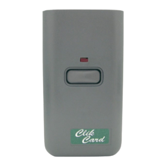
Page 5: Part 1 Introduction And Basics
PART 1 INTRODUCTION AND BASICS The ClikCard Narrow Band Residential Garage Door Receiver is designed to mount directly to any three-terminal garage door operator. It can also be remotely installed if the operator terminal strip is not accessible or if power is not obtainable from the operator. - Page 6 4. Connect a three conductor, color coded cable onto the receiver's terminals (the connector clips provided with the receiver are not used in this type of installation). 5. Loosen the terminal screws on the operator and insert the other end of the cable under the screw heads.
-
Page 7: Part 2 Narrow Band Garage Door Receiver Programming And Use Guide
(If the “Valid” LED begins to blink when you move switch 3 to “ON”, the receiver’s memory does not contain any ClikCard codes.) 2. Move switch 2 to the "ON" (up) position. When the “Valid” LED begins blinking, all of the transmitters that had been programmed into the receiver will have been erased. -
Page 8: Part 3 Data Validation And Noise Detection
PART 3 DATA VALIDATION AND NOISE DETECTION This section describes how to determine if the radio frequency environment is too noisy for a radio operated system. A. DATA VALIDATION AND NOISE DETECTION The Data Validation and Noise Detection LEDs are located on the controller board to the left of the keypad. -
Page 9: Part 4 Fcc Requirements
PART 4 FCC REQUIREMENTS A. RADIO FREQUENCY This equipment has been tested and found to comply with the limits for a Class B digital device, pursuant to part 15 of the FCC Rules. These limits are designed to provide reasonable protection against harmful interference when the equipment is operated in a residential enviroment.
Need help?
Do you have a question about the ClikCard and is the answer not in the manual?
Questions and answers