Table of Contents
Advertisement
Advertisement
Table of Contents

Related Manuals for ITRON IMR


Summary of Contents for ITRON IMR
- Page 1 Itron Mobile Radio User Guide 14 May 2019 TDC-1719-002...
- Page 2 All other product names and logos in this documentation are used for identification purposes only and may be trademarks or registered trademarks of their respective companies. For more information about Itron or Itron products, go to www.itron.com. If you have questions or comments about a software or hardware product, contact Itron Technical Support Services. Contact Email: support@itron.com...
-
Page 3: Table Of Contents
2. About Your Itron Mobile Radio Itron Mobile Radio Parts List 3. Daily Operation Charging the Portable IMR Battery Charging the Mobile IMR-XA or IMR-FT Battery Turning the Radio On or Off 4. LED Status Indicators Power Indicator LED Table Comm Indicator LED Table 5. - Page 4 Itron Mobile Radio User Guide Installing on a Partition Installing on a Pedestal Removing the IMR-XA from the Mounting Jacket 8. Maintaining your Itron Mobile Radio Cleaning the Radio Case Installing a Replacement Battery Servicing the IMR-XA Charge Base Removing the IMR-XA Charge Base...
- Page 5 Itron Mobile Radio User Guide Itron Mobile Radio compliance Equipment description Itron Mobile Radio PMN: IMR PMN: IMR2 PMN: IMR-XA/IMR-FT FCC ID: EO9IMRA FCC ID: EO9IMRB FCC ID: EO9IMRB IC: 864A-IMRA IC:864A-IMRB IC: 864A-IMRB HVIN: IMRA HVIN: IMRB-INT HVIN: IMRB-EXT FCC USA intentional radiator compliance statement This device complies with Part 15 of the FCC Rules.
- Page 6 Itron Mobile Radio User Guide Compliance Statement Canada Déclaration de Conformité opment Canada (ISED) regulations, this radio trans- Canada, le présent émetteur radio peut fonctionner mitter may only operate using an antenna of a type avec une antenne d'un type et d'un gain maximal (ou and maximum (or lesser) gain approved for the trans- inférieur) approuvé...
- Page 7 Economic Development Canada. The highest SAR value for this Itron Mobile Radio, model IMR when tested for use when worn on the body as described in the user’s guide is 0.25 W/kg (IMRA) and 1.2 W/kg (IMRB). While there may be differences between the SAR levels of various Itron Mobile Radio models and at various positions, they all meet the government requirements for safe exposure.
- Page 8 Itron Mobile Radio User Guide Warning: Warning: Use this device only in a manner consistent with the Itron Mobile Radio User Guide The Australian version of this device has been tested and found to be compliant to Australian standards. It is identified with the RCM mark on the label.
-
Page 9: Feature List
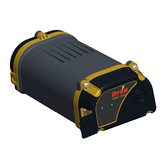
The Itron Mobile Radio is available in several models: the original handheld, portable Itron Mobile Radio (IMR) with a built-in antenna and the new External Antenna and Field Tools versions of the IMR (IMR-XA, IMR-FT) that are mounted in a vehicle for mobile drive-by end- point reading and field tool operations, respectively. - Page 10 Itron Mobile Radio User Guide 1. Introduction Itron Mobile Radio Quick Reference Guide (TDC-1720-xxx) Itron Mobile Radio Compliance Statement (TDC-1722-xxx) 14 May 2019 TDC-1719-002...
-
Page 11: About Your Itron Mobile Radio
When you unpack your radio, make sure you have all of the components listed in the fol- lowing tables. If any are missing, contact Itron Support Services immediately. For the portable IMR, an optional Radio Carrying Kit is available for order separately. The Radio Carrying Kit contains a belt clip and a shoulder harness. - Page 12 Available as a permanent mount with a 17-foot cable cable or a magnetic mount with a 12-foot cable. IMR-XA mounting jacket with Securely holds the IMR-XA and mounts to a seat belt, partition, or adapter plate pedestal. DC power cable Two-meter cable with 12V DC vehicle accessory plug.
-
Page 13: Itron Mobile Radio Compliance
Inspect the radio for broken, loose, or missing parts and fasteners, taking corrective action as required. Ensure that the IMR-XA external whip is securely connected to its mounting base, and the mounting base is securely attached to the vehicle. Make sure the radio is operated and stored within the recommended temperature range. -
Page 14: Turning The Radio On Or Off
IMR-XA / IMR-FT connected to 12V DC vehicle power cable) pressing the button turns the power LED green until the button is released, but it does not turn the radio off. The IMR-XA and IMR-FT radios remain on as long as they are being powered by the vehicle. -
Page 15: Led Status Indicators
Turning on Note: When an IMR with a fully discharged battery is connected to power via its USB cable, it may display a solid white LED or the LED may randomly turn on and then off again. This is normal behavior while a fully discharged battery is charging to a minimum voltage, at which time it should follow the states shown in the Power indicator LED table. -
Page 16: Comm Indicator Led Table
If the white LED never turns off while the IMR is connected to power, the battery is likely bad and must be replaced. This will need to be done approximately every 300 to 500 charge cycles. -
Page 17: Communication Ports
5. Communication Ports The Itron Mobile Radio has one micro USB communication port under a protective rubber flap on the side of the radio near the top. Note: The USB cable supplied with the IMR-XA and IMR-FT has a down-angle micro USB connector to facilitate proper cable management with the mounting jacket. -
Page 18: Carrying The Portable Itron Mobile Radio
6. Carrying the Portable Itron Mobile Radio The portable Itron Mobile Radio’s optional shoulder harness and belt clip provide convenient, hands-free ways to carry the radio while installing, reading, and maintaining meters and end- points. The shoulder harness and belt clip let you wear the radio comfortably while walking or driving. -
Page 19: Installing The Imr-Xa And Imr-Ft
7. Installing the IMR-XA and IMR-FT Refer to the following procedures for guidance on installing your IMR-XA or IMR-FT. Installing the Antenna on the next page Power Cable Routing--All Installations on page 15 Installing the Mounting Jacket in the Vehicle on page 16 IMR-XA / IMR-FT Antenna Specifications This section provides the specifications for the IMR-XA / IMR-FT external vehicle antenna. -
Page 20: Installing The Antenna
Selecting an Antenna Location on the Vehicle The antenna remains installed on the vehicle. The manufacturer's instructions, which ship with the antenna components, are summarized in the following procedures. Itron recom- mends consulting the antenna manufacturer's instructions in addition to this guide. -
Page 21: Installing The Permanent Antenna Mounting Base
9. Thread the antenna base onto the mount body, making sure not to cross-thread the mount. 10. Continue tightening the antenna base until it seats to the vehicle. 11. Complete the cable routing to the IMR-XA in the vehicle and secure the cable. Installing the Magnetic Antenna Mounting Base The magnetic mount antenna base can be installed temporarily on the metal roof or trunk of the vehicle and then removed as desired. -
Page 22: Installing The Dc Power Cable
The DC power supply cable connects to the vehicle's electrical system so you can easily con- nect and disconnect power for the IMR-XA or IMR-FT. The DC power cable is shipped with a vehicle accessory (12V) adapter attached so the cable and the IMR can be easily moved between different vehicles. -
Page 23: Power Cable Routing--All Installations
Power Cable Routing--All Installations 1. Once the mounting location of the IMR is known, select a location in the vehicle for the IMR connector end of the cable so that it reaches the Itron Mobile Radio power jack without put- ting stress on the cable or radio. -
Page 24: Installing The Mounting Jacket In The Vehicle
Installing on a Seat Belt 1. Put the IMR in the mounting jacket and engage the plastic side release buckles. 2. Ensure the IMR is securely encased in the mounting jacket and tighten the straps if neces- sary. 3. Attach the mounting jacket to the seatbelt. -
Page 25: Installing On A Pedestal
2. Use cable ties or some other secure fastener to attach the mounting jacket to the pedestal. 3. Put the IMR in the mounting jacket and engage the plastic side release buckles. 4. Plug in the micro-USB and secure it with the Velcro strap as shown in the following illus- tration. -
Page 26: Removing The Imr-Xa From The Mounting Jacket
Removing the IMR-XA from the Mounting Jacket 1. Unplug the power cable and antenna cable. 2. Unplug the micro-USB and open the Velcro strap. 3. Disengage the plastic side release buckles on the mounting jacket and remove the IMR. 14 May 2019 TDC-1719-002... -
Page 27: Maintaining Your Itron Mobile Radio
Use the rubber flap to protect the radio’s USB port in dusty conditions. Protect the antenna and power connectors on the IMR-XA charge base when the radio is being installed, removed, or carried. The IMR-XA charge base is not water resistant. Protect it from rain and moisture. -
Page 28: Installing A Replacement Battery
8. Maintaining your Itron Mobile Radio Installing a Replacement Battery 1. Make sure the IMR is powered off and disconnected from other power sources. 2. Remove the battery compartment door. For the IMR-XA and IMR-FT you must first remove the charge base. -
Page 29: Removing The Imr-Xa Charge Base
Unscrew four screws to remove the charge base from the IMR-XA. Replacing the Charge Base Antenna Cable 1. Remove the charge base from the IMR-XA. 2. Unscrew the small antenna cable connector (1) from the body of the IMR-XA. 14 May 2019 TDC-1719-002... -
Page 30: Servicing The Imr-Xa External Antenna
Itron Mobile Radio User Guide 8. Maintaining your Itron Mobile Radio 3. Unscrew the large antenna cable connector (2) from the bottom half of the charge base. 4. Install the new cable and screw the charge base back onto the radio. -
Page 31: Inspecting The Antenna Base And Whip
Connector. The center pin of the connector should not be recessed or pushed in to the connector housing. 2. Replace the entire antenna base if the cables or connectors are damaged. Contact Itron Sup- port Services if you need assistance. -
Page 32: Replacing The Antenna Gasket
To maintain the integrity and performance of the antenna, Itron recom- mends that you replace the gasket located in the antenna base minimally once a year. For more information about ordering the gasket, log onto Itron Access or contact Itron Sup- port Services at 1.877.487.6602. -
Page 33: Storing Your Radio
LED Status Indicators on page 7. If you are storing the Itron Mobile Radio for an extended period of time, you should let it remain charging or remove its battery. Note: Remove the Itron Mobile Radio’s battery before storing the device for periods longer than six months. -
Page 34: Battery Basics
AC wall adapter, or a 12V DC car adapter. The Itron Mobile Radio meets the USB 2.0 Power Delivery standards. If the IMR does not charge with your third-party device, validate that your device meets USB 2.0 standards. Not all micro USB connectors meet the USB 2.0 standards. - Page 35 If an IMR has been left in a hot vehicle (above 104° F, 40° C), allow the vehicle and the IMR to cool down before powering the IMR on.
-
Page 36: Safety
Take frequent short breaks. Use these breaks to exercise the muscles in your hands, arms, shoulders, neck, and back. Do not attempt to operate or adjust the IMR-XA or IMR-FT while driving. AC Power Adapter Follow these instructions to help ensure your safety and extend the life of the adapter. -
Page 37: Troubleshooting
12. Troubleshooting If you have a problem with your radio, review the appropriate troubleshooting steps listed in the following table. If the problem remains unresolved, contact an Itron customer service rep- resentative (e-mail: support@itron.com; phone: 1.877.487.6602). Issue and Solution Table... -
Page 38: Radio Readings Tips
Itron Mobile Radio User Guide 12. Troubleshooting Issue Possible Solutions If the IMR has been in a hot vehicle or in full sun, change location and allow it to cool down. If the previous troubleshooting suggestions do not solve the issue, replace the battery. -
Page 39: Optimizing Bluetooth® Performance
3. Run the Itron Bluetooth Pairing Tool on your Windows device. Your Windows device will automatically begin looking for Bluetooth devices to pair with. 4. If necessary, click RESCAN until the IMR you are trying to pair with appears in the list of devices. - Page 40 7. Verify that the Serial port is selected. This must be selected for the radio to connect. If the Serial port check box is not selected, select it and click OK. 8. Close the Itron Pairing Tool. 9. Select your radio from the list of radios in Itron Mobile for FCS. 14 May 2019 TDC-1719-002...
- Page 41 Itron Mobile Radio User Guide 13. Optimizing Bluetooth® Performance If your radio is not listed, click the Refresh button. 14 May 2019 TDC-1719-002...
-
Page 42: Itron Mobile Radio Capabilities And Limitations
Transmit frequency MAS, ISED: 952 MHz–953 MHz Transmit frequency ISM: 908 MHz–923.8 MHz Antenna type: IMR (portable models): internal directional antenna with maximum gain perpendicular to the front face of the Itron Mobile Radio unit. IMR-XA/IMR-FT (in-vehicle mobile models): External vertical omnidirectional whip antenna with 5 dBi gain. - Page 43 14. Itron Mobile Radio Capabilities and Limitations Maximum transmitter power: 10.5 dBm IMR built-in antenna type: integral, chip Itron Mobile Radio The following sections apply only to IMR models sold in those countries: Transmitter Information, Australia Transmit frequency LM: 928 MHz - 930 MHz Transmit frequency SRD: 916 MHz - 926.8 MHz...
Need help?
Do you have a question about the IMR and is the answer not in the manual?
Questions and answers