Table of Contents
Advertisement
Quick Links
INSTALLATION MANUAL
AIR CONDITIONER
• Please read this installation manual completely before installing the product.
• Installation work must be performed in accordance with the national wiring
standards by authorized personnel only.
• Please retain this installation manual for future reference after reading it
thoroughly.
TYPE: Wall Mounted
P/NO : MFL67798106
www.lg.com
Advertisement
Table of Contents

Related Manuals for LG MULTI V


Summary of Contents for LG MULTI V
- Page 1 • Please read this installation manual completely before installing the product. • Installation work must be performed in accordance with the national wiring standards by authorized personnel only. • Please retain this installation manual for future reference after reading it thoroughly. TYPE: Wall Mounted www.lg.com P/NO : MFL67798106...
-
Page 2: Table Of Contents
Wall Mounted Type Indoor Unit Installation Manual TABLE OF CONTENTS Installation Requirements Required Parts Required Tools Installation Parts ....3 Safety Precautions....4 ❏ Installation guide map ❏ Level gauge ❏ Four type "A" screws & plastic ❏ Screw driver Installation ❏ Electric drill anchors ❏... -
Page 3: Installation Parts
Installation Parts Installation Parts Standard Accessories Type "A" screw Name Installation panel (Other) SE: 6 EA Quantity 1 set • Owner's manual S5: 8 EA • Installation manual Shape WIRED REMOTE CONTROLLER INSTALLATION • Since the room temperature sensor is in the remote controller, the remote controller box should be installed in a place away from direct sunlight, high humidity and direct supply of cold air to maintain proper space temperature. -
Page 4: Safety Precautions
Safety Precautions Safety Precautions To prevent injury to the user or other people and property damage, the following instructions must be followed. ■ Be sure to read before installing the air conditioner. ■ Be sure to observe the cautions specified here as they include important items related to safety. ■... - Page 5 Safety Precautions Do not modify or extend the Do not let the air conditioner Be cautious when unpacking power cable. run for a long time when the and installing the product. humidity is very high and a door or a window is left open. •...
- Page 6 Safety Precautions ■ Installation Always check for gas (refrig- Install the drain hose to Keep level even when erant) leakage after installa- ensure that water is drained installing the product. tion or repair of product. away properly. • Low refrigerant levels may •...
-
Page 7: Installation
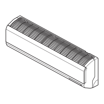
Installation Installation Read completely, then follow step by step. Selection of the best location There should not be any heat source or steam • near the unit. Front • There should not be any obstacles to prevent the air circulation. Left •... -
Page 8: Piping Method
Installation Piping Method ■ Preparing the indoor unit's piping and drain hose for 3. Tape the tubing, drain hose and the connecting cable. Be sure that the drain hose is located at the installation through the wall. ■ Remove the plastic tubing retainer(see illustration lowest side of the bundle. - Page 9 Installation ■ Tighten the flare nut with a wrench. ■ Bundle the piping and drain hose together by wrapping them with vinyl tape over the range with- in which they fit into the rear piping housing sec- Spanner (fixed) tion. Flare nut Connection Torque...
- Page 10 Installation 3. Insert the connecting cable into the indoor unit. Pipe Size[Torque] ■ Don't connect the cable to the indoor unit. LIQUID ■ Make a small loop with the cable for easy connec- Ø12.7[5.5kgf . m] Ø6.35[1.8kgf . m] tion later. Ø15.88[6.6kgf .
- Page 11 Installation ■ Bundle the piping and drain hose together by 10. Indoor unit installation ■ Remove the spacer. wrapping them with cloth tape over the range ■ Ensure that the hooks are properly seated on the within which they fit into the rear piping housing section.
- Page 12 Installation Installation Information. For left piping. Follow the instruction below. Good case • Press on the upper side of clamp and unfold the tubing to downward slowly. ※ Make the space between the tubing and the rear panel Bad case •...
-
Page 13: Drain Piping
Installation Drain Piping 1. To remove the front panel from the indoor unit, 2. To check the drainage. ■ Pour a glass of water on the evaporator. remove the front panel from the indoor unit ■ Ensure the water flows through the drain hose of cabinet. - Page 14 Installation Central controller Outdoor unit Indoor unit Terminal Block Indoor Outdoor unit 1(L) 2(N) SODU SODU IDU IDU INTERNET DRY1 DRY2 GND INDOOR POWER INPUT 2) Attach the Grille onto the cabinet. • Grasp lower the left and right side of the Grille and engage four tabs on the top inside edge of the chassis.
-
Page 15: Installation Of Wirelss Remote Controller
Installation Installation of wirelss remote controller How to insert the Batteries 1. Remove the battery cover by pulling it according to the arrow direction. 2. Insert new batteries making sure that the (+) and (-) of battery are installed correctly. 3. -
Page 16: Installation Of Wired Remote Controller
Installation Installation of Wired Remote Controller 1. Please fix tightly using provided screw after placing remote controller setup board on the place where you like to setup. - Please set it up not to bend because poor setup could take place if setup board bends. Please set up remote controller board fit to the reclamation box if there is a reclamation box. - Page 17 Installation 4. Please connect indoor unit and remote controller using connection cable. Please check if connector is normally connected. Indoor Unit side Connecting cable 5. Please use extension cable if the distance between wired remote controller and indoor unit is more than 10m.
-
Page 18: Name And Function Of Wired Remote Controller(Accessory)
Installation Name and function of wired remote controller(Accessory) 1. Operation indication screen 2. Set temperature button • It will set not room temperature but outlet air temperature. 3. Fan speed button • Fan Speed have 3 Steps. • Middle and Low step is same 4. -
Page 19: Installer Setting Mode
Installation Group Control Setting Installer setting mode is to set the detail function of the remote controller. If the installer setting mode is not set correctly, it can cause problems to the product, user injury or property damage. This must be set by an certificated installer, and any installation or change that is carried out by a non-certificated person should be responsible for the results. -
Page 20: Group Control Setting
Installation 1. Group Control 1 n Wired remote controller 1 + Indoor units LGAP Network System Slave Master Slave Signal Slave 12 V Display Error Message Only connect serial signal and GND lines between slave indoor unit Master 1. It is possible to 16 indoor units(Max) by one wired remote controller. Set only one indoor unit to Master, set the others to Slave. - Page 21 Installation 2. Group Control 2 LGAP Network System Slave Slave Slave Master Signal 12 V Donʼt connect serial 12V line Display Error Message Master Slave h It is possible to control N indoor units by wired remote controller M units. (M + N ≤ 17 Units) Set only one indoor unit to Master, set the others to Slave.
- Page 22 Installation 3. Group Control 3 n Mixture connection with indoor units and Fresh Air Intake Unit LGAP Network System Signal Master Slave Master Slave 12 V Display Error Message Master Master h In case of connecting with standard indoor unit and Fresh Intake Unit, separate Fresh Air Intake Unit with standard units.
- Page 23 Installation 4. 2 Remote Control n Wired remote controller 2 + Indoor unit 1 LGAP Network System Master Display Error Message Master Slave 1. It is possible to connect two wired remote controllers with one indoor unit. 2. Every types of indoor unit is possible to connect two remote controller. 3.
- Page 24 Installation 5. Accessories for group control setting It is possible to set group control by using below accessories. Indoor unit 2 EA +Wired remote controller Indoor unit 1 EA +Wired remote controller 2EA ❈ PZCWRCG3 cable used for connection ❈ PZCWRC2 cable used for connection S lave Mas te r PZC WRC 2...
Need help?
Do you have a question about the MULTI V and is the answer not in the manual?
Questions and answers