Advertisement
Quick Links
Advertisement

Related Manuals for Tevo LITTLE MONSTER


Summary of Contents for Tevo LITTLE MONSTER
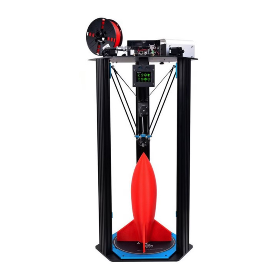
- Page 1 TEVO LITTLE MONSTER Page 1 of 22...
- Page 2 ASSEMBLY BAG B-3-1 M6 x 20mm Rubber Stand BAG A-2-2 M5 x 15mm - 12 Extrusion 4080 - 3 Base Plate Page 2 of 22...
- Page 3 BAG A-10 Pre-Assembled Page 3 of 22...
- Page 4 BAG A-2-2 M5 x 15mm - 12 Top Plate Page 4 of 22...
- Page 5 BAG A-8 M4 x 10mm - 12 Motor bracket M3 x 6mm - 12 20T Pulley Page 5 of 22...
- Page 6 Page 6 of 22...
- Page 7 BAG A-2-1 Pre-Assembled Page 7 of 22...
- Page 8 BAG B-3-2 M5 x 20mm Spacer Bed Frame Heat Bed BAG A-9-1 M3 x 6mm Brass Standoff Optical Endstop - 3 Page 8 of 22...
- Page 9 BAG A-7 M4 x 16mm - 12 Connecting Rod - 6 Page 9 of 22...
- Page 10 BAG A-1 M5 x 8mm - 4 Page 10 of 22...
- Page 11 BAG A-13 Extruder Belt Note: Pre-cut and insert PTFE tube into hotend making sure it is FULLY inserted. Page 11 of 22...
- Page 12 BAG A-3 M3 x 6mm Brass Standoff M3 x 6mm - 10 Page 12 of 22...
- Page 13 BAG A-4 M4 x 10mm Power Supply Box BAG A-5 Note: Connect touch-screen ribbon cable to Aux 1 of main control board. Page 13 of 22...
-
Page 14: Electrical Wiring
ELECTRICAL WIRING 1) Connect the 4-pins cable sockets from Power Supply box to Main Control Board box. 2) Connect the 2-pins cable sockets from Power Supply box to Heat Bed connector. 3) Connect the 2-pins white thermistor cable from Sbase TH2 to Heat Bed. Page 14 of 22... - Page 15 FIRST POWER ON & AUTO-CALIBRATION Bed will heat up to 80ºC. Perform Auto-Axis Calibration. Perform Auto Bed Leveling. System Auto Reset. Page 15 of 22...
-
Page 16: Touch Screen Operations
TOUCH SCREEN OPERATIONS MAIN MENU SUB-MENU Manual heat control of hotend & heat bed temperatures. Manual movements of all X,Y,Z axis Page 16 of 22... - Page 17 Manual homing of all axis Printing file selections Manual filament extrusion & retract Page 17 of 22...
- Page 18 Part cooling fan manual control Setup & Special functions Additional BLTouch functions Page 18 of 22...
-
Page 19: Repetier Host Setup
REPETIER HOST SETUP Page 19 of 22... - Page 20 Page 20 of 22...
- Page 21 Select "Slic3r" as slicer. Click "Configuration". Go to "File" and click "Load Config Bundle". Select and load "Monster.ini" from SD card. Rename print setting, filament, printer to Monster and save. Page 21 of 22...
- Page 22 Recommended starting and ending Gcode for printing. G30 Z2.0 indicate BLTouch trigger point is 2mm below nozzle tip. Please adjust this value according to the first layer print result. Increase this value will lower nozzle closer to bed. (Example: G30 Z2.0 to G30 Z2.2) Decrease this value will lift nozzle away from bed.
Need help?
Do you have a question about the LITTLE MONSTER and is the answer not in the manual?
Questions and answers