Table of Contents
Advertisement
2200Q2JE-HO-KHM-N_2015.02.
Ammonia Semi-Hermetic Motor
with
K-series Compressor
Instruction Manual
[N6KHM45]
This instruction manual mainly describes the assembly/disassembly way of the semi
hermetic motor with the K-series compressor. Refer and follow
to "Reciprocating
Compressor K-series Instruction manual" for the compressor section.
Before conducting the work of operation/inspection/maintenance of this product, read
this manual and sufficiently understand.
Specifications of this product and contents of this manual are subject to change
without prior notice due to technical improvements.
Advertisement
Table of Contents

Related Manuals for mycom K Series

Summary of Contents for mycom K Series
- Page 1 2200Q2JE-HO-KHM-N_2015.02. Ammonia Semi-Hermetic Motor with K-series Compressor Instruction Manual [N6KHM45] This instruction manual mainly describes the assembly/disassembly way of the semi hermetic motor with the K-series compressor. Refer and follow to "Reciprocating Compressor K-series Instruction manual" for the compressor section. Before conducting the work of operation/inspection/maintenance of this product, read this manual and sufficiently understand.
-
Page 2: Preface
2200Q2JE-HO-KHM-N_2015.02. Preface Preface Thank you for purchasing the K-series Ammonia Semi-hermetic Compressor (hereafter referred to as "this product") of MAYEKAWA Mfg. Co., Ltd. (hereafter referred to as "MAYEKAWA"). This model has an excellent feature of the K-series ammonia compressor that we developed on the basis of the wealth of accumulated technology of industrial reciprocating compressors. -
Page 3: Warranty And Disclaimer
2200Q2JE-HO-KHM-N_2015.02. Warranty and Disclaimer Warranty and Disclaimer Warranty If malfunctions or damages occur under proper usage and conditions following documents such as instruction manual or drawings of this product, or, if MAYEKAWA judges that malfunctions or damages are related to design or manufacture of the product, and if the malfunctions or damages are within the warranty period, we will repair or replace the product without any charges. -
Page 4: Important Information
2200Q2JE-HO-KHM-N_2015.02. Important Information Important Information Intended Use of this Product This product is a general purpose reciprocating compressor to be used for refrigeration, cold storage, or air conditioning. Do not use this product for any purposes other than the intended use or outside the scope of the specification. - Page 5 2200Q2JE-HO-KHM-N_2015.02. Important Information "Tag-out" is to prevent improper work of other people by attaching a tag plate that indicates "work in progress", for example. "Tag-out" is to place a tag that clearly indicates that it is prohibited to operate the energy cut-off device while the (driving) energy source is being shut down.
-
Page 6: About This Manual
2200Q2JE-HO-KHM-N_2015.02. Important Information About this Manual This product is subject to continuous development and improvement without prior notice. Accordingly, the details provided in this manual may partly differ from the actual condition. If any problem is found during work, please contact one of our sales or service establishments. For each sight of MAYEKAWA, refer to following URL. -
Page 7: Table Of Contents
2200Q2JE-HO-KHM-N_2015.02. Table of Contents Table of Contents Preface .......................... i Revision history ...................... i Warranty and Disclaimer ..................... ii Warranty ........................ ii Disclaimer of Warranty ..................ii Important Information ....................iii Intended Use of this Product ................iv Precautions for the Safe Use of this Product ............iv About this Manual .................... -
Page 8: Table Of Contents
2200Q2JE-HO-KHM-N_2015.02. Table of Contents Chapter 3 Installation Safety Precautions during Installation............3-1 Installation Work ..................3-1 3.2.1 Unpacking ......................3-1 3.2.2 Storage ....................... 3-1 3.2.3 Transportation ..................... 3-2 3.2.4 Preparation for Installation .................. 3-4 3.2.5 Installation ......................3-4 3.2.5.1 Placement ....................3-4 3.2.5.2 Piping ...................... -
Page 9: Chapter 1 Safety
2200Q2JE-HO-KHM-N_2015.02. Chapter 1 Safety Chapter 1 Safety Strict Requirements and Prohibitions 1.1.1 Strict Requirements (Do’s) 1.1.1.1 General Strictly observe any applicable laws and regulations. In an explosive atmosphere, never use this product. Each package unit using this product must be installed with necessary safety devices and protection systems. -
Page 10: Do's On Lock-Out/Tag-Out Procedures After Power Is Off
2200Q2JE-HO-KHM-N_2015.02. Chapter 1 Safety Before working on any problem encountered during operation, before setting up this product, before cleaning work, and before conducting maintenance or inspection work, be sure to check that the internal pressure of this product and the refrigeration/cold storage/air conditioning unit is at the atmospheric pressure. -
Page 11: Do's On The Response To Emergency Situations
2200Q2JE-HO-KHM-N_2015.02. Chapter 1 Safety 1.1.1.7 Do’s on the Response to Emergency Situations Develop an emergency action plan according to the applicable legal requirements and post it at a safe place. 1.1.1.8 Do’s on the Disposal of Waste Oil, Waste Liquid, Scraps, etc. ... -
Page 12: Residual Risks
2200Q2JE-HO-KHM-N_2015.02. Chapter 1 Safety Residual Risks The following information is provided assuming that this product will be operated, inspected, and maintained while it is used in a general refrigeration, cold storage, or air conditioning system. However, it is impossible for us to foresee all hazardous sources in the particular refrigeration, cold storage, or air conditioning system that the customer will actually use. - Page 13 2200Q2JE-HO-KHM-N_2015.02. Chapter 1 Safety Table 1-2 Hazardous Sources (continued) Actions to take During Actions to Take During Hazardous Area Predicted Hazard Cleaning, Inspection, or Operation Parts Replacement Contact with or Wearing a personal Wearing a personal Discharge (side) Stop Valve inhalation of protection gear...
-
Page 14: Safety Devices
2200Q2JE-HO-KHM-N_2015.02. Chapter 1 Safety Figure 1-1 Warning label pasting position (ex.: N6KHM45) Safety Devices For safe use of this product and for the devices for safety, protection and control that are required to protect this product, refer to the "Reciprocating Compressor K-series instruction manual" Section 1.4. The motor of this product is equipped with a thermostat that operates at 130°C, but not with any other protective devices. -
Page 15: Chapter 2 Product Specifications And Structure
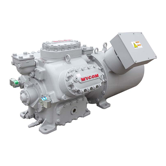
2200Q2JE-HO-KHM-N_2015.02. Chapter 2 Product Specifications and Structure Chapter 2 Product Specifications and Structure Overview of This Product This K-series ammonia semi-hermetic compressor that has newly joined K-series is a small size reciprocating model that is completely free from the leakage of its shaft seal part by docking semi-hermetic water cooled motor to allow this product to serving as a dedicated compressor to the use for ammonia refrigerant. -
Page 16: Product Specifications
2200Q2JE-HO-KHM-N_2015.02. Chapter 2 Product Specifications and Structure Product Specifications 2.3.1 Standard Specifications The standard specifications of the ammonia semi-hermetic compressor are shown in Table 2-1 and the standard specifications of the semi-hermetic motor are shown in Table 2-2. Table 2-1 Standard Specifications of the K-series Ammonia semi-hermetic Compressors Model Item N8KHM60... - Page 17 2200Q2JE-HO-KHM-N_2015.02. Chapter 2 Product Specifications and Structure Table 2-2 Standard Specifications of the K-series Semi-hermetic Motor Product Model Name Item N8KHM60 N4KHM30 N6KHM45 NHM60 Motor model name NHM30 NHM45 Motor type Three-phase induction motor Rating output Number of pole 200 / 200 / 220 Rating voltage 400 / 400 /440 Rating frequency...
-
Page 18: Service Limits
2200Q2JE-HO-KHM-N_2015.02. Chapter 2 Product Specifications and Structure 2.3.2 Service Limits Table 2-2 Service Limits for the K-series Compressor Item Unit Limit value Remarks Maximum discharge Design pressure of a crankcase 2.26 pressure and covers: Maximum suction High pressure part: 26MPa 0.69 pressure Low pressure part: 1.5MPa... -
Page 19: Outer Dimensions
2200Q2JE-HO-KHM-N_2015.02. Chapter 2 Product Specifications and Structure 2.3.3 Outer Dimensions Figure 2-2 Outer Dimensions of the K-series Ammonia Semi-hermetic Compressor Ammonia Semi-hermetic Motor with K-series Compressor 2.3 Product Specifications... -
Page 20: Structure Of Semi-Hermetic Motor
2200Q2JE-HO-KHM-N_2015.02. Chapter 2 Product Specifications and Structure Structure of Semi-hermetic Motor 2.4.1 Sectional View of the Motor Figure 2-3 Sectional View of the K-series Semi-hermetic Motor Ammonia Semi-hermetic Motor with K-series Compressor 2.4 Structure of Semi-hermetic Motor... -
Page 21: Parts Configuration Table
2200Q2JE-HO-KHM-N_2015.02. Chapter 2 Product Specifications and Structure 2.4.2 Parts Configuration Table Table 2-4 Parts Configuration Table of the K-series Semi-hermetic Motor Part Name Remarks Compressor Crankcase N4KHM,N6KHM,N8KHM,N62KHM Compressor Crankshaft 4K,6K,8K,62K Compressor Shaft Key M15×9.7×60 Compressor Oil Seal Retainer Gasket, Compressor Oil Seal Retainer Fastening Bolt, Compressor Oil Seal Retainer M8×35 Compressor Oil Seal... - Page 22 2200Q2JE-HO-KHM-N_2015.02. Chapter 2 Product Specifications and Structure Part Name Remarks Gasket, Motor End Cover Fastening Bolt, Motor End Cover M8×25 Motor Sealing Terminal Box Gasket, Motor Sealing Terminal Box Fastening Bolt, Motor Sealing Terminal Box Hexagon Head Cap Screw M12×35 Motor Terminal Block Gasket, Motor Terminal Block Fastening Bolt, Motor Terminal Block...
-
Page 23: Chapter 3 Installation
2200Q2JE-HO-KHM-N_2015.02. Chapter 3 Installation Chapter 3 Installation Safety Precautions during Installation The description in this Chapter 3 "Installation" assumes that this product is to be installed in a generic and commonly used refrigeration, cold storage, or air conditioning system. If the installation procedures described in this chapter are not directly applicable to the customer's specific refrigeration, cold storage, or air conditioning system, the customer is requested to prepare a separate work procedure document by paying sufficient attention to the... -
Page 24: Transportation
2200Q2JE-HO-KHM-N_2015.02. Chapter 3 Installation 3.2.3 Transportation Should this product being lifted drop, there is a high risk of death or severe injury. Provide sufficient protection such that no one can enter an area below this product being lifted up. For the mass of this product, refer to Table 2-1 in this manual Chapter 2 Section 2.3.1 "Standard Specifications". - Page 25 2200Q2JE-HO-KHM-N_2015.02. Chapter 3 Installation Example for Lifting Up this product: For slinging up this product, the use of belt slings or wire ropes (hooking wire) facilitates the lifting in an equalized load at each of the four eye bolts. If no hook is attached to each of the belt slings or wire ropes, hang the load by using each of the eye bolts and the eye (ring) of the lifting tools via a shackle.
-
Page 26: Preparation For Installation
2200Q2JE-HO-KHM-N_2015.02. Chapter 3 Installation 3.2.4 Preparation for Installation Installation space Prepare an installation space of this product where the operation, cleaning, maintenance, and inspection work can be easily performed. For performing overhaul of the compressor: Because the crankshaft must be taken out from the main body during an overhaul work, a sufficient space must be provided on the oil pump side, for a length corresponding to the full width of the crankshaft, as measured from the crankcase end. -
Page 27: Chapter 4 Operation Of Compressor And System ・・・・・・・・・・・・・4-1
2200Q2JE-HO-KHM-N_2015.02. Chapter 4 Operation of Compressor and System Chapter 4 Operation of Compressor and System For the following items description is required in this chapter, please refer to the "Reciprocating Compressor K-series Instruction Manual" Chapter 4. Requirements for the lubricating oil (refrigerating oil) of this product ... -
Page 28: Chapter 5 Maintenance And Inspection
2200Q2JE-HO-KHM-N_2015.02. Chapter 5 Maintenance and Inspection Chapter 5 Maintenance and Inspection Precautions for Maintenance and Inspection When reading this Section, also refer to Section 1.1 in this manual Chapter 1. When entering the machine room for maintenance services, ensure that sufficient ventilation has been started and measure the oxygen concentration so that there is no risk of oxygen deficiency. - Page 29 2200Q2JE-HO-KHM-N_2015.02. Chapter 5 Maintenance and Inspection In the disassembly/inspection workplace, secure a sufficient space for temporary storage of the removed parts and tools, replacement parts, and for the disassembling work as well as safety passages, and then put up necessary off-limit signs. ...
-
Page 30: Contents Of Maintenance And Inspection
2200Q2JE-HO-KHM-N_2015.02. Chapter 5 Maintenance and Inspection Contents of Maintenance and Inspection 5.2.1 Daily Management and Regular Inspection For the daily maintenance and regular inspection, refer to the "Reciprocating Compressor K-series instruction manual", Section 5.2 and exercise every corresponding item. Particularly for this product, properly control its cooling water in its flow rate, water quality and temperature, conduct regular inspection and cleaning of the strainer and water channels to maintain the cooling system in normal condition. -
Page 31: Overhauling The Entire Motor
2200Q2JE-HO-KHM-N_2015.02. Chapter 5 Maintenance and Inspection 5.2.3.2 Overhauling the Entire Motor Conduct the overhaul at intervals of 2 year or 16,000 hours, whichever earlier, after the commissioning. Besides the overhaul contents of the motor jacket, remove the motor end cover, motor bearing retainer, motor casing, motor rotor and compressor oil seal retainer to inspect the internal parts. -
Page 32: Disassembly
2200Q2JE-HO-KHM-N_2015.02. Chapter 5 Maintenance and Inspection Disassembly 5.3.1 Refrigerant Gas Recovery Since the semi-hermetic motor is integrated with the compressor, the ammonia refrigerant inside must be recovered before overhauling. There are a few methods of recovering the refrigerant. For example, one method is to operate the refrigerator, close the supply source valve, turn the gas into liquid, and recover the liquid at the receiver. -
Page 33: Motor Jacket Cover
2200Q2JE-HO-KHM-N_2015.02. Chapter 5 Maintenance and Inspection 5.3.3 Motor Jacket Cover The overhaul of motor jacket cover involves the overhauling items described in Section 5.3.1.1 and 5.3.1.2. When performing the work described in Section 5.3.1.1 (inspection and cleaning the inside of jacket) alone, remove the two jacket hoses for motor cooling and two tubes ( 8 mm) for motor bearing Φ... - Page 34 2200Q2JE-HO-KHM-N_2015.02. Chapter 5 Maintenance and Inspection g) Attach the jacking bolts in the threaded holes at four spots on the motor jacket cover flange surface. Gradually retract the jacket cover by turning a half turn at a time of each of the four jacking bolts (following picture to the left).
-
Page 35: Motor End Cover
2200Q2JE-HO-KHM-N_2015.02. Chapter 5 Maintenance and Inspection 5.3.4 Motor End Cover (approx. 2.3kg) The motor end cover shown in the picture right is fixed to the motor bearing retainer [614] with eight bolts [622]. To take it off, remove the bolts and pull the cover toward yourself. ... - Page 36 2200Q2JE-HO-KHM-N_2015.02. Chapter 5 Maintenance and Inspection 5.3.6 Motor Bearing Outer Race and Motor Oil Seal The outer race of motor bearing [613] is mounted in the motor bearing retainer [614]. As long as the bearing does not show any particular abnormality, there is no need of removing it. In case of replacing the motor bearing, remove the snap ring A [613-1] for the motor bearing (following picture to the left) and pull the bearing outer race toward yourself to take it off.
-
Page 37: Motor Casing
2200Q2JE-HO-KHM-N_2015.02. Chapter 5 Maintenance and Inspection 5.3.7 Motor Casing The motor casing and the motor rotor described on the next page are heavy items. To remove them, be sure to use a crane or other lifting device. a) Prepare the set-up to lift up the motor casing by using a crane or chain block and hooking the lifting tool. -
Page 38: Motor Rotor
2200Q2JE-HO-KHM-N_2015.02. Chapter 5 Maintenance and Inspection 5.3.8 Motor Rotor Table 5-4 Mass of the Motor Rotor a) Likewise the case of motor casing, prepare the set-up to lift up the motor rotor [607] by using Motor Model NHM30 NHM30 NHM30 a crane or chain block and hooking the lifting Mass (kg) -
Page 39: Compressor Oil Seal And Retainer
2200Q2JE-HO-KHM-N_2015.02. Chapter 5 Maintenance and Inspection 5.3.9 Compressor Oil Seal and Retainer a) The compressor oil seal retainer [26] (picture to the right) is located inside the motor spacer [600] and mounted to the crank case [1] of the compressor with six bolts [28]. It can be taken off by loosening and removing the bolts and pulling toward yourself. -
Page 40: Motor Spacer
2200Q2JE-HO-KHM-N_2015.02. Chapter 5 Maintenance and Inspection 5.3.10 Motor Spacer (NHM30/NHM43: 29 kg, NHM60: 37 kg) As long as no gas or oil leakage has been checked from the joint section of the motor spacer gasket [601] in a daily inspection or monthly regular inspection, there is no particular need to overhaul the motor spacer [600]. -
Page 41: Reassembly
2200Q2JE-HO-KHM-N_2015.02. Chapter 5 Maintenance and Inspection Reassembly When replacing a part, check if it is a correct one or not before using it for assembling. Start the reassembly work after completing the cleaning of assembly parts and tools. Most of the reassembly work will be performed in the reverse order of the disassembly work. -
Page 42: Compressor Oil Seal And Motor Oil Seal
2200Q2JE-HO-KHM-N_2015.02. Chapter 5 Maintenance and Inspection 5.4.1 Compressor Oil Seal and Motor Oil Seal When the replacement of compressor oil seal [32] and motor oil seal [617] is required, use the following procedure for the assembling. The size of oil seals for the compressor and motor is different, but the mounting method is the same. -
Page 43: Compressor Oil Seal Retainer
2200Q2JE-HO-KHM-N_2015.02. Chapter 5 Maintenance and Inspection 5.4.2 Compressor Oil Seal Retainer a) Apply oil on the gasket [27] and attach it to the oil seal retainer [26] while allowing the bolt holes to match the oil holes (picture to the right). b) Apply oil on the lip (in contact with shaft) of the oil seal and the sealing area of the compressor crank shaft. -
Page 44: Motor Rotor
2200Q2JE-HO-KHM-N_2015.02. Chapter 5 Maintenance and Inspection 5.4.3 Motor Rotor a) Motor rotor [607] is a heavy component. In the same way as in the disassembly, prepare the set-up to lift up the motor rotor by using a chain block and lifting tool (see Section 5.3.8). ... -
Page 45: Motor Casing
2200Q2JE-HO-KHM-N_2015.02. Chapter 5 Maintenance and Inspection 5.4.4 Motor Casing ● When mounting a motor casing, pay meticulous attention to avoid damaging the coil end of the motor casing with rotor fins. Damaged coil insulation coating may cause burn-out of the motor. a) Motor casing [603] is a heavy component. -
Page 46: Motor Bearing And Motor Oil Seal Retainer
2200Q2JE-HO-KHM-N_2015.02. Chapter 5 Maintenance and Inspection 5.4.5 Motor Bearing and Motor Oil Seal Retainer a) When the bearing has been removed for the replacement of motor bearing [613], mount the bearing in the motor bearing retainer [614]. After inserting the outer race that is in pair with the planetary ring of the bearing (following picture to the left), attach the snap ring A [613-1] for motor bearing in the groove in front side (following picture to the right). -
Page 47: Motor Bearing Retainer
2200Q2JE-HO-KHM-N_2015.02. Chapter 5 Maintenance and Inspection 5.4.6 Motor Bearing Retainer a) Apply oil on the planetary ring of the motor bearing [613] and the lip part (in contact with the shaft) of the motor oil seal [617]. b) Screw two stud bolts (safety bolts) into appropriate top bolt holes. -
Page 48: Motor Jacket Cover
2200Q2JE-HO-KHM-N_2015.02. Chapter 5 Maintenance and Inspection 5.4.8 Motor Jacket Cover Motor jacket cover [610] is a heavy component. In the same way as in the disassembly (see Section 5.3.3), prepare the set-up to lift up the jacket cover by using a chain block and the eye bolts (hanging bolts) provided at two spots on top of the jacket cover. -
Page 49: Oil Supply/Oil Return Piping To Motor Bearing
2200Q2JE-HO-KHM-N_2015.02. Chapter 5 Maintenance and Inspection 5.4.9 Oil Supply/Oil Return Piping to Motor Bearing a) For feeding and returning oil for the motor bearing, fix the two pipes ( 8 mm) connecting the motor Φ end cover [620] and motor spacer [600] (following picture). b) Screw in the nuts for the joint located at both ends of the pipe at each joint and tighten them. - Page 50 [N4KHM30] [N8KHM60]...
- Page 51 2200Q2JE-HO-KHM-N_2015.02. MAYEKAWA MFG. CO., LTD. 3-14-15 Botan Koto-ku, Tokyo 135-8482, JAPAN Phone : +81 (0)3-3642-8181 : http://www.mayekawa.com/...
Need help?
Do you have a question about the K Series and is the answer not in the manual?
Questions and answers