Table of Contents
Advertisement
Available languages
Available languages
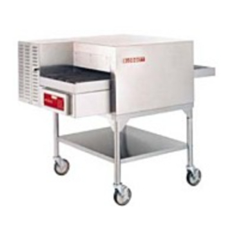
MT1828G AND MT1828E
CONVEYOR OVENS
INSTALLATION -- OPERATION -- MAINTENANCE
MT1828G ET MT1828E
FOURS À BANDE TRANSPORTEUSE
MANUEL D'INSTALLATION -- FONCTIONNEMENT -- ENTRETIEN
BLODGETT OVEN COMPANY
www.blodgettcorp.com
50 Lakeside Avenue, Box 586, Burlington, Vermont 05402 USA Telephone (800) 331-5842, (802) 860-3700 Fax: (802)864-0183
PN M9946 Rev D (6/01)
E 2000 --- G.S. Blodgett Corporation
Advertisement
Table of Contents

Subscribe to Our Youtube Channel
Related Manuals for Blodgett MT1828E


Summary of Contents for Blodgett MT1828E
- Page 1 FOURS À BANDE TRANSPORTEUSE MANUEL D’INSTALLATION -- FONCTIONNEMENT -- ENTRETIEN BLODGETT OVEN COMPANY www.blodgettcorp.com 50 Lakeside Avenue, Box 586, Burlington, Vermont 05402 USA Telephone (800) 331-5842, (802) 860-3700 Fax: (802)864-0183 PN M9946 Rev D (6/01) E 2000 --- G.S. Blodgett Corporation...
-
Page 2: For Your Safety
WARNING: IMPROPER INSTALLATION, ADJUSTMENT, ALTERATION, SERVICE OR MAINTENANCE CAN CAUSE PROPERTY DAMAGE, INJURY OR DEATH. READ THE INSTALLATION, OPERATING AND MAINTENANCE INSTRUCTIONS THOROUGHLY BEFORE INSTALLING OR SERVICING THIS EQUIPMENT AVERTISSEMENT: UNE INSTALLATION, UN AJUSTEMENT, UNE ALTÉRATION, UN SERVICE OU UN ENTRETIEN NON CONFORME AUX NORMES PEUT CAUSER DES DOMMAGES À... - Page 3 THE REPUTATION YOU CAN COUNT ON UNE RÉPUTATION SUR LAQUELLE VOUS POUVEZ COMPTER For over a century and a half, The Blodgett Oven Company has been building ovens and nothing but ovens. We’ve set the industry’s quality standard for all kinds of ovens for every foodservice operation regardless of size, application or budget.
- Page 4 Your Service Agency’s Address: Adresse de votre agence de service: Model/Modèl: Serial Number/Numéro de série: Your oven was installed by/ Installateur de votre four: Your oven’s installation was checked by/ Contrôleur de l’installation de votre four:...
-
Page 5: Table Of Contents
Introduction Oven Description and Specifications Oven Components ....Installation Delivery and Inspection ....Oven Location and Ventilation Oven Assembly . -
Page 6: Introduction
The result is a high quality product, cooked at a lower temperature in a shorter amount of time. Blodgett conveyor ovens represent the latest ad- vancement in energy efficiency, reliability, and ease of operation. Heat normally lost, is recircu-... -
Page 7: Oven Components
Conveyor Assembly -- conveyor belt and rack assembly that carries product through the oven. Control Box --- contains electrical wiring, cooling fan, drive motor and drive chain. Drive Motor --- provides power to move the con- veyor belt. Located inside the control box. Drive Chain --- connects the drive motor sprocket to the drive side conveyor belt support sprocket. -
Page 8: Installation
Installation Delivery and Inspection All Blodgett ovens are shipped in containers to prevent damage. Upon delivery of your new oven: Inspect the shipping container for external dam- age. Any evidence of damage should be noted on the delivery receipt which must be signed by the driver. -
Page 9: Oven Location And Ventilation
Blodgett oven, please contact your local distributor. If you do not have a local dis- tributor, please call the Blodgett Oven Company at 0011-802-860-3700. WARNING: Failure to properly vent the oven can be... -
Page 10: Oven Assembly
Installation Oven Assembly OVEN STAND WITH CASTERS NOTE: Install the locking casters on the front of the stand. 1. Attach each leg with casters to the stand frame with a lock washer and nut. DO NOT tighten completely. 2. Position the shelf between the legs with the smooth surface facing the top of the stand. -
Page 11: Stacking The Ovens (If Applicable)
STACKING THE OVENS (if applicable) Double Stacked 1. Assemble the bottom oven to the stand. 2. Rest the top oven on its back. Install the oven alignment pins (4) into the four holes provided on the bottom of the oven 3. -
Page 12: Conveyor Belt
Installation Oven Assembly CONVEYOR BELT 1. Slide the conveyor assembly (with pulley on end of shaft) through the left hand tunnel opening. The sprocket must be located inside the control panel after being pushed into the oven. Refer to Figure 6. 2. -
Page 13: Speed Control
3. Unless specified otherwise, conveyor travel is factory set for left to right operation when fac- ing the front of the oven. If a direction change is required, the polarity of the drive motor must be reversed. Turn the oven OFF and inter- SPEED CONTROL change the black and white motor leads at the... -
Page 14: Crumb Pans
Installation Oven Assembly CRUMB PANS 1. Install crumb pans under each end of the con- veyor. 2. Slide the product stop over the outer edge of the idle side crumb pan. Figure 9 OPTIONAL REMOTE COMPUTER CONTROL 1. Drill the mounting holes for the cooking com- puter support base. -
Page 15: Utility Connections
If you have any questions regarding the proper installation and/or operation of your Blodgett oven, please contact your local distributor. If you do not have a local dis- tributor, please call the Blodgett Oven Company at 0011-802-860-3700. -
Page 16: Gas Connection
Installation Gas Connection GAS PIPING A properly sized gas supply system is essential for maximum oven performance. Piping should be sized to provide a supply of gas sufficient to meet the maximum demand of all appliances on the line without loss of pressure at the equipment. Example: NOTE: BTU values in the following example are for natural gas. -
Page 17: Pressure Regulation And Testing
PRESSURE REGULATION AND TESTING Each oven has been adjusted at the factory to op- erate with the type of gas specified on the rating plate attached to the left side of the control panel. Each oven is supplied with a regulator to maintain the proper gas pressure. -
Page 18: Gas Hose Restraint
Local and National installation standards. Lo- cal installation codes and/or requirements may vary. If you have any questions regarding the prop- er installation and/or operation of your Blodgett oven, please contact your local distributor. If you do not have a local distributor, please call the Blodgett Oven Company at 0011-802-860-3700. -
Page 19: Electrical Connection
MT1828E U.S. and Canadian installations The MT1828E is available in either 1Φ or 3Φ mod- els. Single phase models require a 60Hz, 208/240VAC, 3 wire service consisting of L1, L2 and ground. Three phase models require a 60Hz, 208/240VAC, 4 wire service consisting of L1, L2, L3 and ground. - Page 20 Supply MT1828G 220/230/240 Supply MT1828E Single Phase U.S. and Canadian Installations Supply 208-240 Oven Supply MT1828E Three Phase Delta System Supply Oven MT1828E Three Phase Delta System Supply Oven MT1828E Three Phase WYE System Figure 13 208/240 Oven MT1828E Single Phase...
-
Page 21: Safety Tips
ACHIEVEMENT OF OPTIMUM PERFORMANCE AND LONG, TROUBLE-FREE SERVICE. Please take the time to read the following safety and operating instructions. They are the key to the successful operation of your Blodgett conveyor oven. SAFETY TIPS For your safety read before operating What to do if you smell gas: DO NOT try to light any appliance. -
Page 22: Cooking Computer
Operation Cooking Computer CONTROL DESCRIPTION 1. DIGITAL DISPLAY --- displays the time, tem- perature and controller related information. 2. OVEN ON/OFF --- controls power to the oven. 3. NUMERIC KEYS --- used to enter numbers in the programming mode. 4. CLEAR KEY --- clears the display if an error is made in the programming mode. - Page 23 OPERATION To turn the oven on: 1. Turn the manual gas valve to ON. (Gas models only) 2. Press and hold the ON/OFF key (2). The dis- play reads OFF when the oven is idle. 3. The STATUS LAMPS (9) light. The fans begin to run.
-
Page 24: Oven Adjustments For Cooking
The combination of belt time, oven temperature, and air flow are important for achieving quality re- sults from your Blodgett conveyor oven. Use the following guidelines to adjust the belt time and oven temperature of your unit. For questions re-... - Page 25 Oven Adjustments for Cooking Air Flow Plate Product Clearance Adjustment Plate Figure 15 Operation Block-Off Plate...
-
Page 26: Maintenance Cleaning
Maintenance Cleaning WARNING!! Always disconnect the power supply be- fore cleaning or servicing the oven. WARNING!! If a gas oven needs to be moved, the gas must be turned off and disconnected from the unit before removing the restraint. Re- connect the restraint after the oven has been returned to its original location. - Page 27 5. MT1828G --- Lubricate the combustion air blower motor with six drops of Anderal #465 If maintenance is required contact your local ser- vice company, a factory representative or the Blodgett Oven company. Maintenance WARNING!! Always disconnect the power supply be- fore cleaning or servicing the oven.
-
Page 28: Control Box Component Locations
Maintenance Control Box Component Locations MT1828G Cooling Fans Motor Drive Board Regulator Valve Burner Blower Assembly Figure 17... - Page 29 Cooling Fans Motor Drive Board Contactor Heating Element Maintenance Control Box Component Locations MT1828E Conveyor Motor Figure 18 Heating Elements...
-
Page 30: Troubleshooting Guide
*Denotes remedy is a difficult operation and should be performed by qualified personnel only. It is recommended, however, that All repairs and/or adjustments be done by your local Blodgett service agency and not by the owner/operator. Blodgett cannot as- sume responsibility for damage as a result of servicing done by unqualified personnel. - Page 31 *Denotes remedy is a difficult operation and should be performed by qualified personnel only. It is recommended, however, that All repairs and/or adjustments be done by your local Blodgett service agency and not by the owner/operator. Blodgett cannot as- sume responsibility for damage as a result of servicing done by unqualified personnel.
-
Page 32: Introduction
à celle obtenue dans un four traditionnel, cuit à une température inférieure dans un délai plus court. Les fours à bande transporteuse Blodgett sont des fours à gaz à chauffage direct qui utilisent des produits à combustion à haute température pour la cuisson. -
Page 33: Caractéristiques
240 VAC, 3Φ, 60Hz, 4 fils, 26 ampères Exportation et l’Australie 240 VAC, 1Φ, 50Hz, 3 fils, 45 ampères 208-240 VAC, 3Φ, 50Hz, 4 fils, 30 ampères 380/220 VAC, 3Φ, 50Hz, 5 fils, 18 ampères 415/240 VAC, 3Φ, 50Hz, 5 fils, 17 ampères Aucun Aucun Introduction MT1828E/AA... -
Page 34: Description Et Composantes Du Four
Introduction Description et Composantes du Four Montage à convoyeur: Ce sont la courroie du convoyeur et le montage à crémaillère qui portent l’aliment à travers le four. Boîtier de commande: contient les câblages élec- triques, ventilateur de refroidissement ou volets, mo- teur d’entraînement et courroie d’entraînement. -
Page 35: Installation
Tous les fours sont expédiés en conteneurs. A la réception de votre four Blodgett vous devez: Vérifier que les emballages ne sont pas abimés. Toute défection dans l’emballage doit être no- tée sur l’accusé de reception de la marchan- dise; celui-ci doit être signé par le chauffeur. -
Page 36: Implantation Et Aération Du Four
Les codes d’installation et/ou les exi- gences peuvent varier d’une localité à l’autre. Si vous avez des questions portant sur l’installation et/ou l’utilisation adéquate de votre four Blodgett, veuillez contacter votre distributeur local. Si aucun distributeur local n’est situé dans votre localité, veuillez appeler Blodgett Oven Company au 0011-802-860-3700. -
Page 37: Montage Du Four
BASE DE SUPPORT DU FOUR AVEC ROULETTES REMARQUE:Les roulettes freinées doivent être tour- nées vers le devant du chariot. 1. Fixez chaque pied doté de roulettes au cadre, à l’aide d’une rondelle de blocage et d’un boulon. NE serrez PAS complètement. 2. -
Page 38: Superposition Des Fours
Installation Montage du Four SUPERPOSITION DES FOURS (si applicable) Section Double 1. Attachez la partie inférieure du four au support. 2. Poser le four du haut sur le dos. Insérer les broches d’alignement (4) dans les quatre tr 3. Enlevez les quatre bouchons éjectables situés sur le dessus du four inférieur. -
Page 39: Le Convoyeur
LE CONVOYEUR 1. Glisser le corvoyeur (avec poulis d’engrenage à la fin) dans l’ouverture gauche. Le pignon doit se trouver à l’intérieur du panneau de commande après avoir été enfoncé dans le four. Reportez-vous à la Figure 24. Installation 2. Installer la ceinture à l’autours du moteur et la poulis d’engrenage du corvoyeur. - Page 40 Installation Montage du Four 3. Sauf indication contraire, le déplacement de la bande transporteuse est réglé à l’usine pour se faire de gauche à droite lorsqu’on re- garde le devant du four. Si un changement de sens s’avère nécessaire, la polarité du moteur d’entraînement doit être inversée.
-
Page 41: Plateaux Pour Miettes
PLATEAUX POUR MIETTES 1. Installez des plateaux pour miettes sous cha- que extrémité du convoyeur. 2. Glissez la barre d’arrêt des produits sur l’ex- trémité du côté libre du ramasse-miettes. Figure 27 Installation L’ORDINATEUR DE CUISSON DÉTACHÉ 1. Percer les trous de montage pour la base de support de l’ordinateur de cuisson. -
Page 42: Branchements De Service
Les codes d’installation et/ou les exi- gences peuvent varier d’une localité à l’autre. Si vous avez des questions portant sur l’installation et/ou l’utilisation adéquate de votre four Blodgett, veuillez contacter votre distributeur local. Si aucun distributeur local n’est situé dans votre localité, veuillez appeler Blodgett Oven Company au 0011-802-860-3700. -
Page 43: Branchement De Gaz
CONDUIT DE GAZ Un système d’alimentation en gaz de bon calibre est essentiel pour obtenir le meilleur rendement du four. Les conduits doivent être calibrés pour fournir suffisamment de gaz pour alimenter tous les appareils sur le conduit sans perte de pression à... - Page 44 Installation Branchement de Gaz RÉGLAGE ET TEST DE PRESSION Tous les fours sont réglés en usine en fonction du type de gaz spécifié sur la plaque signalétique. Cette plaque est fixée au côté gauche du panneau de commande. Pour maintenir la bonne pression de gaz, chaque four est livré...
- Page 45 Les codes d’installation et/ou les exi- gences peuvent varier d’une localité à l’autre. Si vous avez des questions portant sur l’installation et/ou l’utilisation adéquate de votre four Blodgett, veuillez contacter votre distributeur local. Si aucun distributeur local n’est situé dans votre localité, veuillez appeler Blodgett Oven Company au 0011-802-860-3700.
-
Page 46: Raccordement Électrique
MT1828E Installations aux États-Unis et au Canada Les fours MT1828E sont disponibles en 1Φ ou 3Φ (en option). Les modèles monophasés requiert 60 Hz, 208/240Vc.a., service de 3 fils composé de L1, L2 et Terre. Les modèles triphasés requiert 60 Hz, 208/240Vc.a., service de 4 fils composé... - Page 47 MT1828G 220/230/240 Alimentation MT1828E 1Ô Alimentation 208-240 Four Alimentation Alimentation Four 415/380 415/380 Alimentation Four Figure 31 Installation Raccordement Électrique 208/240 Four MT1828E 1Ô 208/240 Four MT1828E 3Ô DELTA 208/240 Four MT1828E 3Ô DELTA 415/ 240/ Four MT1828E 3Ô WYE...
-
Page 48: Utilisation
MALES DU SYSTEME ET D’EN OBTENIR UN SERVICE DURABLE ET SANS ENCOMBRES. Prenez le temps de lire attentivement les instruc- tions qui suivent. Vous y trouverez la clé du succès du four à transportbande Blodgett. CONSEILS DE SÉCURITÉ Pour la sécurité, lire avant d’utiliser l’ap- pareil Que faire s’il y a une odeur de gaz :... -
Page 49: Identification Des Commandes
IDENTIFICATION DES COMMANDES 1. AFFICHAGE - Indique la durée et la tempéra- ture, ainsi que d’autres informations relatives au fonctionnement du four. 2. MARCHE/ARRÊT --- Allume ou éteint le four. 3. CLAVIER NUMÉRIQUE --- Utiliser le clavier nu- mérique pour programmer l’heure et la température de cuisson désirée. - Page 50 Utilisation L’Ordinateur de Cuisson UTILISATION Pour allumer le four 1. Tourner la vanne de gaz sur MARCHE. (Modèles à gaz seulement) 2. Appuyer et maintenir momentanément la touche MARCHE/ARRÊT (2). L’affichage indique OFF lorsque le four est inactif. 3. Les témoins lumineux VENTILATEUR et CHAUFFAGE (9) s’allumeront.
-
Page 51: Réglages Du Four Pour La Cuisson
à con- voyeur Blodgett. Utilisez les lignes directrices qui suivent pour ajuster le temps de passage de la courroie et la température du four de votre unité. - Page 52 Utilisation Réglages du Four Pour la Cuisson Plaque de circulation d’air Plaque de dégagement des aliments Figure 33 Plaque de blocage...
-
Page 53: Entretien Nettoyage
MISE EN GARDE!! Débranchez toujours la source d’ali- mentation électrique avant de nettoyer ou d’entretenir le four. MISE EN GARDE!! Si le four doit être déplacé, l’arrivée de gaz doit être coupée et débranchée avant d’enlever la bride. Rebranchez la bride lorsque le four a été... - Page 54 #465 pétrole. Si un entretien est requis, contactez votre bureau de service local, un représentant du fabricant ou Blodgett Oven. MISE EN GARDE!! Débranchez toujours la source d’ali- mentation électrique avant de nettoyer ou d’entretenir le four.
-
Page 55: Emplacement Des Composants Du Boîtier De Commande
Entretien Emplacement des Composants du Boîtier de Commande MT1828G Ventilateurs de refroidissement Carte de L’entraînement moteur Valve régulateur de gas Assemblage de soufflante de brûleur Figure 35... - Page 56 Entretien Emplacement des Composants du Boîtier de Commande Ventilateurs de refroidissement Carte de L’entraînement moteur Élément de chauffage du contacteur MT1828E Moteur du convoyeur Figure 36 Éléments de chauffage...
-
Page 57: Guide De Dépannage
TOUT réglage et/ou TOUTE réparation à un agent commercial ou représentant local Blodgett. Blodgett ne saura être tenu responsable d’un dommage résultant d’une répara- tion ou d’un service d’entretien effectué par un personnel non qualifié. - Page 58 TOUT réglage et/ou TOUTE réparation à un agent commercial ou représentant local Blodgett. Blodgett ne saura être tenu responsable d’un dommage résultant d’une répara- tion ou d’un service d’entretien effectué par un personnel non qualifié.
- Page 59 INSERT WIRING DIAGRAM HERE PLACER SCHÉMA DE CÂBLAGE...
Need help?
Do you have a question about the MT1828E and is the answer not in the manual?
Questions and answers