Advertisement
Quick Links
Advertisement

Related Manuals for Easy ELC12 Series

Summary of Contents for Easy ELC12 Series
- Page 1 - 1 -...
-
Page 2: Brief Introduction
Ethernet network. Furthermore the visualization of the whole system is possible and easy to realize by a personal computer. U p d a t e d : March , 2 0 11 sales@xlogic-relay.com... - Page 3 How to connect hardware before Ethernet module running ? 1. Set ELC12-E-Ethernet module IP address.(refer to software first part) 2. Link the ELC12-E-Ethernet to the xLogic SuperRelay system (which must contain a ELC-12 CPU module) 3. Link the ELC12-E-Ethernet to internet by net wire, then use PC or other monitor device for monitoring or download & upload of users’...
- Page 4 Software part: Device IP factory setting The default IP adress of Ethernet module is:192.168.0.178 Network segment check of PC and Ethernet module’s Users need ensure that PC has Ethernet cards,and that the network settings of PC and Ethernet module’s must keep in the same network segment before establishing communication between PC and Ethernet module.
- Page 5 Step two: Select “ZnetCom2.exe” file, and start it with double-click the left key of your mouse. In order to enable your Ethernet module to link to Ethernet, you are required to connect your Ethernet module (ELC12-E-Ethernet-DC/AC) to your computer by net router. You are allowed to connect the Ethernet module to Ethernet directly by common net cable.
- Page 6 You are required to set as following way, otherwise the Ethernet module may fail to work , please take some time to study the below instruction carefully : Power on ELC12-E-Ethernet-AC/DC module and click to search Ethernet. At the same time the searching Windows will pop out as the follow figure .
- Page 7 Double-click the device in the list of equipment; or select equipment items, click the toolbar button or button in attributes Bar, as shown in the following Figure "Getting device information" dialog box. Double click module information Then the information of Ethernet module would show as follow. - 7 -...
- Page 8 Note: All the contents in the red frame region cannot be adjusted. That’s to say, you must select the items as follows in red circle. - 8 -...
- Page 9 Note: Baudrate can be set “4800” ,”9600”,”19200” and the corresponding communication port must be set the same baudrate ,just the COM3 in the ELC-12 CPU. The target port and target IP can be set up to 4 groups. Note: Just as above figure shows, parameters in “Target IP1,Target IP2, Target IP3, Target IP4” must be adjusted to be exactly same as those in your PCs which will use to communicate with ELC12-E-Ethernet module.
- Page 10 Save your settings The settings about ELC12-E-Ethernet can be saved in XML format by clicking button. Import exited settings Existing configuration of ELC12-E-Ethernet can be imported called by clicking button. Second part: Communication and monitor with xLogicSoft. Link ELC12-E-Ethernet to ELC-12 CPU module 2.
- Page 11 4. To search “PLC’s IP” by clicking “Search” button Port number and PLC’s IP pre-configure in Znetcom soft as below figure. Click "Connect to PLC" button, and then the Ethernet module and PC will be linked. After the Ethernet module and PC being linked, many features can come true, e.g. downloading user program into xLogic CPU module ,uploading program into PC and online monitor (monitor real time status of xLogic IO)can be done, herewith Ethernet module just plays a role of ELC-RS232/USB cable.
- Page 12 C. Monitor program run status: click Option 2: ELC12-E-Ethernet unit work under TCP serve mode, xLogicsoft software as Client. In addition, if more than one CPU module would be required in certain application/project system, then communication between those CPU modules has to be realized via Ethernet module, in this application, please note that each CPU module must require one Ethernet module to be linked to.
-
Page 13: Mounting Hole Layout
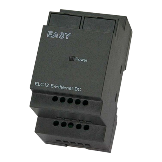
Mounting Hole Layout 1. ELC-12 CPU 2. ELC12-E-ETHERNET Model ELC12-E-Ethernet-DC ELC12-E-Ethernet-AC Supply Voltage DC 12-24V AC 110-240V - 13 -...
Need help?
Do you have a question about the ELC12 Series and is the answer not in the manual?
Questions and answers