Table of Contents
Advertisement
Advertisement
Table of Contents

Related Manuals for Easy xLogic

Summary of Contents for Easy xLogic
- Page 3 Content � Introduction � Getting started � Installation and wiring � Programming xLogic � xLogic Functions � Configuring � Applications � Software Technical data � 1 1 1 1...
- Page 4 DIN-rail and panel-mounted options are both are available, offering full flexibility to the various installation needs of your application. The xLogic SuperRelay is available in 120V/240V AC or 12V and 24V DC versions, making it the ideal solution for relay replacement, or simple control applications as building and parking lot...
- Page 5 Valid Valid range range this this manual manual Valid Valid range range of of this this manual manual The manual applies to devices of ELC series modules . For more information about SMS module or Ethernet module ,please refer to the SMS module or Ethernet module user's manual. Safety Safety Safety...
- Page 6 Additional support support Additional Additional support support We take pride in answering your question as soon as we can: Please consult our website at www.xLogic-relay.com for your closest point of contact or email us at sales@xlogic-relay.com 4 4 4 4...
-
Page 7: Table Of Contents
3.1 Connectors…………………………………………………………………………………………………………………………….33 3.2 Blocks and block numbers………………………………………………………………………………………………….34 3.3 From circuit diagram to xLogic program……………………………………………………………………………..36 3.4 The four golden rules for operating xLogic………………………………………………………………………….37 3.5 Overview of xLogic menus……………………………………………………………………………………….…………38 3.6 Writing and starting the circuit program…………………………………………………………………………..38 3.6.1 Selecting programming mode…………………………………………………………………………………………38 3.6.2 The first circuit program………………………………………………………………………………………………….40 3.6.3 Circuit program input……………………………………………………………………………………………………..40... - Page 8 5.2.6 Set backlight………………………………………………………………………………………………………………….…173 5.2.7 Set baud rate of CPU………………………………………………………………………………………………………174 5.2.8 Modification Methods of System Time…………………………………………………………………………..…175 6 6 6 6 .Application .Application .Application .Application………………………………………………………………………………………………………………………….177 6.1 Dual-function switch………………………………….…………………………………………………………………….177 6.1.1 Standard solution…………………………………………………………………………………………………………….178 6.1.2 The scheme of xLogic……………………………………………………………………………………………………….180 6.2 Automatic gate…………………………………………………………………………………………………………………..181 6 6 6 6...
- Page 9 6.4.2 The scheme of xLogic………………………………………………………………………………………………………186 6.5 Daylight lamp system……………………………………………………………………………………………………….187 6.5.1 Standard solution…………………………………………………………………………………………………..………188 6.5.2 The scheme of xLogic………………………………………………………………………………………………………188 6.6 Rainwater pump……………………………………………………………………………………………………………………189 6.6.1 Standard solution……………………………………………………………………………………………………………190 6.6.2 The scheme of xLogic………………………………………………………………………………………………………191 7 7 7 7 ..xLogic xLogic xLogic Software Software xLogic Software Software…………………..…………………….………………………………………………….…………………192 7 7 7 7 .1Connecting...
- Page 10 . Data adjustments can be done via the on-board keypad and LCD display, or with xLogic soft. It can be either DIN-rail or panel mounted, depending upon the needs of your application, and it is available in 120V/240V ac as...
- Page 11 CPU) CPU) * xLogic digital modules are available for opera tion with 12…24V DC, and 110.. .240 V AC, and are equipped with eight inputs and eight outputs. * xLogic analog modules are available for operation with 12…24 V DC and are equipped with six digital and two analog inputs.
- Page 12 ELC-USB). It is kind of communication cable with photoelectricity isolation through which PC with USB port only can be connected to xLogic main module, moreover, it has same features as ELC-RS232 module, so it is quite convenient for user whose computer has no standard serial port.
- Page 13 Module box to the Ethernet. The project down- and upload to and from the main modules and the communication between the main modules happens over the Ethernet network. Furthermore the visualization of the whole system is possible and easy to realize a personal computer.
- Page 14 Note Note xLogic Main Module may be equipped with expansion modules of the different voltage class, but expansion module must be supplied the correct power corresponding to its type. Each xLogic Main Module provides the following connections for the creation of the circuit program, regardless of the num ber of connected blocks: �...
- Page 15 Naming Naming Naming Naming Rules Rules Rules Rules of of ELC ELC Series Series Series Series Model name(main module): 1. Series name 2. Points of input and output 3. Supply power AC or DC 4. Digital/Analog D: digital DA: digital/analog L: with photoelectricity isolation 5.
- Page 16 Connection cable between ELC-12 CPU and ELC-HMI-FP (Faceplate) for long-distance application purpose, one and half meters standard length (customizable) Faceplate ( ELC-HMI’s installation unit), making it possible for ELC-HMI to be externally installed in the front door of cabinet for easy observation and operation ELC-HMI-FP while ELC-12 CPU is required to be installed inside.
- Page 17 485 converter,used to bring out the terminals of RS485 port built-in ELC-12 series CPU for connection with third party devices. Accessories ELC-RS232 RS232 communication module /download cable between PC and xLogic CPU units ELC-USB USB communication module /download cable between PC and xLogic CPU units ELC-Ethernet-DC/AC...
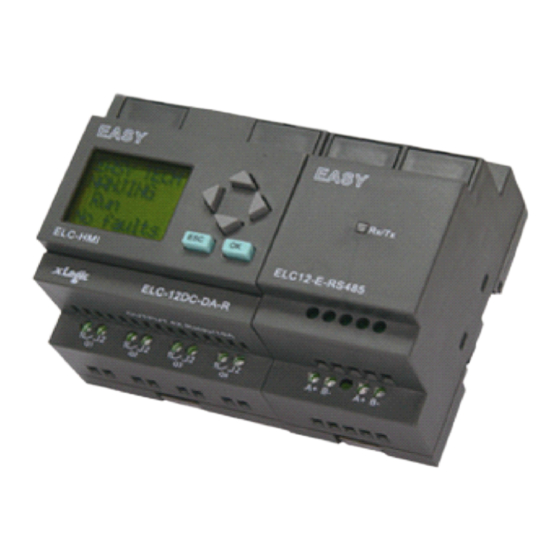
- Page 18 Structure Structure Structure Structure 1. ELC-18 Series CPU 1.Power supply 2. Input 3. Program/RS232 port 4. HMI/LCD panel 5. keypad 6.Expansion+RS485 port 7.Output 2. ELC-12 Series CPU 1. Power supply 2.Input 3. Program/RS232 port 4.Extension/RS485 port 5..HMI/LCD panel 6.keypad 7.Output Notes: 1.
- Page 19 3. ELC-E Series Expansion Module(only use with ELC-18 CPUs) 1. Power supply 2. Input 3. Connection cable 4. Extension port 5. Output ELC12-E Series Expansion Module (also apply to ELC-6 Series CPU ) 1.Power supply 2. Input 3..extension port (left) 4.expansion port(Right)( Program port for applied to ELC-6 CPU) 17 17 17 17...
- Page 20 Dimensions Dimensions Dimensions The xLogic installation dimensions are compliant with DIN 43880. xLogic can be snap-mounted to 35 mm DIN rails to EN 50022 or on the wall. xLogic width: � ELC-12 Series Main Module has a width of 72mm.
- Page 21 Removal Removal To remove xLogic: ..if you have installed only one xLogic Basic: 1. Insert a screwdriver into the eyelet at the bottom of the slide interlock and move the latch downward. 2. Swing the xLogic Basic off the DIN rail.
-
Page 22: Wall-Mounting
Wall-mounting For wall-mounting, first slide the mounting slides on the rear side of the devices towards the outside. You can now wall-mount xLogic by means of two mounting slides and two Ø M4 screws (tightening torque 0.8 to 1.2 Nm). -
Page 23: Mouting Elc-Hmi-Fp
ELC-HMI-FP ,Faceplate ( ELC-HMI’s installation unit), making it possible for ELC-HMI to be ELC-HMI-FP ELC-HMI-FP ELC-HMI-FP externally installed in the front door of cabinet for easy observation and operation while ELC-12 CPU is required to be installed inside. ELC-HMI-FP To prepare the mounting surface for the optional ELC-HMI-FP... - Page 24 1. Cut a 91 mm x 91 mm (tolerance: +0.5 mm) hole in the mounting surface. 2. Put the ELC-HMI into ELC-HMI-FP module. ELC-HMI-FP ELC-HMI-FP 3. Fit the ELC-HMI-FP ELC-HMI-FP (as the above figure ,not include the lock part) into the cutout you made in the mounting surface.
- Page 25 Wire the xLogic using a screwdriver with a 3-mm blade. You do not need wire ferrules for the terminals. You can use conductors with cross-sections of up to the following thicknesses: � 1 x 2.5 mm �...
- Page 26 The ELC-18AC and ELC-12AC versions of xLogic are suitable for operation with rated voltages of 110 V AC and 240 V AC. The ELC-18DC and ELC-12DC versions can be operated with a 12 or 24 VDC power supply.
- Page 27 Status 1 must be greater than 50ms, and when the switch status changes from 1 to 0, the time of Status 0 also must be greater than 50ms. Connecting xLogic xLogic is is is is shown shown in in in the following figures: 2.Connecting...
- Page 28 * * * * ELC-18AC ELC-18AC ELC-18AC ELC-18AC Series Series Series Series and and ELC-12AC ELC-12AC ELC-12AC ELC-12AC inputs inputs inputs inputs * * * * ELC-Analog ELC-Analog ELC-Analog Inputs Inputs (DC 0 0 0 0 … … … … 10V) 10V) 10V) ELC-Analog Inputs...
- Page 29 The above figure shows how to make a four-wire current measurement. Connect two-wire sensor to ELC-E-AI(I). Two-wire sensor wiring is as follows: 1. Connect the output of the sensor to the “I” terminal (0…20mA current measurement) of ELC-E-AI(I) module. 2. Connect the attached connector of the sensor to the +24V(L+) of power supply. 3.
- Page 30 Various loads such as lamp, fluorescent tube, motor, contact, etc., can be connected to the outputs of xLogic. The maximum ON output current that can be supplied by xLogic is 10A for the resistance load and 2A for the inductive load. The connection is in accordance with the...
- Page 31 * The “+” terminal of the output wiring must be connected with the DC positive voltage, and it must be connected with the “L+” terminal of the xLogic power ,a load must be connected with the “-” terminal of the DC negative voltage.
- Page 32 * The “-” terminal of the output wiring must be connected with the DC negative voltage, and it must be connected with the “M” terminal of the xLogic power ,a load must be connected with the “+” terminal of the DC positive voltage.
- Page 33 Actually, ELC-RS485 is just a convertor with photo isolation bringing out 3 wiring terminals from RS485 port (2x8pin) of CPU for your easy connection with other devices, If “RT1”, RT2” terminal are short connected, one 120R resistor will be connected between A/+ and B/- 2.2.4...
- Page 34 function others NULL 2. Expansion port/RS485 ( pin definition) 3------RS485 A 5------RS485 B 4------GND 6------GND 7------CANL 9------CANH 15------+5V 16------+5V Communication between CPU and expansion module will use 4.7,9,15 pin. ELC-RS485 module need when ELC-18 CPU communicate with the third party devices via RS485 bus ELC-12 CPUs...
- Page 35 1. Programming port/RS232 port(ELC-RS232 ,ELC-USB,ELC-Copier should be inserted in this port) Named COM1. When the programming port should be used as the standard RS232 port (D-shape 9 pin header) ,the ELC-RS232 cable needed. 2. Expansion port/RS485 ( pin definition(2X3 pin female figure) 1------RS485 A1 6------RS485 B1 2------RS485 A2...
-
Page 36: Programming Programming Programming Programming Xlogic Xlogic Xlogic Xlogic
● Lastly, you will enter this program directly in xLogic. It will take you only a few pages of this manual to store your first executable circuit program in the xLogic unit. With suitable hardware (switches etc.), you will then be able to carry out initial tests. -
Page 37: Blocks And Block Numbers
This chapter shows you how to use xLogic elements to create complex circuits and how blocks and I/O are interconnected. In the topic "From circuit diagram to xLogic Program" you will learn how to transform a conventional circuit into a xLogic circuit program. - Page 38 Display Display Display The figure below shows a typical view of the xLogic Display. As you can see, it can show only one block at a time. We have therefore introduced block numbers to help you check the circuit structure.
- Page 39 By using the xLogicSoft software to program xLogic , you can directly create a function chart of your circuit program. xLogic Soft also allows you to assign eight character names to up to 512 blocks, and to view these on the xLogic Display in parameter assignment mode.
- Page 40 The output of the AND block controls the relay at output Q1. The load E1 is connected to output Wiring Wiring Wiring Wiring example example example example The following figure shows you the wiring, based on a 220 V AC version of xlogic. 3.4 4 4 4 The The four four four four golden golden golden...
- Page 41 After you have designed a circuit, you want to write it to your xLogic. The small example below shows how to do this. 3.6 6 6 6 .1 .1 .1 .1 Selecting Selecting...
- Page 42 Switch xLogic to programming mode by pressing ESC. This will take you to the main menu of xLogic: The first character in the first line is the ">" cursor. Press to move the ">" cursor up Program.. and down. Move it to "Program..
- Page 43 Let us now take a look at the following parallel circuit consisting of two switches. Circuit diagram The corresponding circuit diagram Translated into a xLogic circuit program this means: Relay K1 is (at output Q1) is controlled by means of an OR block. Circuit program S1 is connected to the I1 and S2 to the I2 input connector of the OR block.
- Page 44 Select GF (basic functions) by pressing the key until GF appears, and confirm with OK. xLogic now shows the first block from the list of basic functions: The AND is the first block of the basic function list.
- Page 45 Press OK. I1 is now connected to the input of the OR block. The cursor jumps to the next input of the OR block. The display now shows: Your complete circuit program in xLogic up to now: Now you connect input I2 to the input of the OR block: 1. Switch to editing mode: Press OK...
- Page 46 Note Note xLogic has now saved your circuit program to nonvolatile memory. The circuit program remains in the xLogic memory until you explicitly delete it. You can save the actual values of special functions in the case of a power outage assuming that these functions support the "Retentive"...
- Page 47 Let us assume you want to name your circuit program "ABC": 1. Select " A": Press 2. Move to the next letter: Press 3. Select " B": Press 4. Move to the next letter: Press 5. Select " C": Press 6.
- Page 48 We shall use the first circuit program as a basis for the second, with some slight modifications. First of all take a look at the circuit diagram for the second circuit program: This is the circuit program layout in xLogic: 46 46 46 46...
-
Page 49: The Four Golden Rules For Operating Xlogic
(in RUN: Press ESC to enter the parameter assignment mode. Select the 'Stop' command, confirm with OK, then move the '>' cursor to 'Yes', and once again confirm with OK). For additional details, see the topic "The four golden rules for operating xLogic ". 2. On the main menu, select "Program"... - Page 50 Now you set the off-delay time T: 1. Move the cursor to Par, if it not already at this position: Press 2. Switch to editing mode: Press OK xLogic shows the parameters in the parameter assignment window: 48 48 48 48...
- Page 51 To change the time value: ● Press to position the cursor. ● Press to modify the value at the relevant position. ● Confirm your entries with OK. Setting Setting Setting Setting the the time time time time Set the time T = 12:00 minutes: 1.
- Page 52 This program branch for Q1 is now completed. xLogic shows you the output Q1. You can once again view the circuit program on the display. Use the keys to browse the circuit program; that is, press or to move from block to block, and to move between the inputs at a block.
- Page 53 The size of a circuit program in xLogic is limited by the memory space (memory used by the blocks). Up to 512 blocks can be used in xLogic. Indication Indication available available...
- Page 54 Inputs Inputs Inputs Input blocks represent the input terminals of xLogic. Up to 260 digital inputs are available to you. In your block configuration, you can assign an input block a new input terminal, if this terminal is not already used in the circuit program.
- Page 55 Outputs Outputs Output blocks represent the output terminals of xLogic. You can use up to 254 outputs. In your block configuration, you can assign an output block a new terminal, provided this terminal is not already used in your circuit program.
- Page 56 View View in in in in the the circuit circuit circuit circuit diagram diagram diagram diagram View View View View in in in in xLogic xLogic xLogic xLogic Name Name Name Name of of the the basic basic basic basic...
- Page 57 .2.1 .2.1 .2.1 AND (Symbol in xLogic) The output of an AND function is only 1 if all all inputs are 1, i.e. when they are closed. A block input that is not used (x) is assigned: x = 1.
- Page 58 (Symbol in xLogic) least least The output of an AND with edge evaluation is only 1 if all all inputs are 1 and at at least least one one input was 0 during the last cycle. The output is set to 1 for the duration of one cycle and must be reset to 0 for the duration of the next cycle before it can be set to 1 again.
- Page 59 4 4 4 4 .2.4 .2.4 .2.4 .2.4 NAND NAND NAND NAND with with with with edge edge edge edge evaluation evaluation evaluation evaluation The output of a NAND with edge evaluation is only 1 at at least least least least one one input is 0 and all all inputs were...
- Page 60 (Symbol in xLogic) The output of an OR is 1 if at at least least least least one one input is 1 hat, i.e. when it is closed. A block input that is not used (x) is assigned: x = 0.
- Page 61 Output 4 4 4 4 .2.7 .2.7 .2.7 .2.7 XOR (Symbol in xLogic) different The XOR (exclusive OR) output is 1 if the signal status of the inputs is different different different. A block input that is not used (x) is assigned: x = 0.
- Page 62 The output is 1 if the input is 0. The NOT block inverts the input status. Advantage of the NOT, for example: xLogic no longer requires break contacts. You simply use a make contact and convert it into a break contact with the help of the NOT function.
- Page 63 Because of slight tolerances in the characteristics of elec tronic components, the set time T may deviate. The xLogic has a maximum tolerance of ± 0.02 %. When 0.02 % of the time T is smaller than 0.02 seconds, the maximum deviation is 0.02 seconds.
-
Page 64: Second Circuit Program
Because you can not always process the range of values from 0 to 1000 as predetermined by xLogic, you can multi ply the digital values by a gain factor and then shift the zero of the range of values (offset). This allows you to output an analog value to the xLogic display, which is proportional to the actual process variable. - Page 65 –30 to +70℃, 0 to 10 V DC (i.e. 0 to 1000 in xLogic). Actual value = (internal value ∙gain) + offset, thus –30 = (0 ∙A) + B, i.e. offset B = –30 = (1000 ∙A) –30, i.e. gain A = 0.1...
-
Page 66: Special Special Special Functions Functions Functions List List
“0”; a logical “0” it converts into a logical “1”. The table also specifies whether the relevant function can be set retentivity (Rem). The following SFs are available: View View View View in in in in xLogic xLogic xLogic xLogic Name Name... - Page 67 Analog value monitoring Analog amplifier Analog multiplexer Pulse Width Modulator(PWM) Analog math Analog ramp PI controller Analog math error detection Miscellaneous Latching relay Pulse relay Message texts Softkey Shift register Data latchg relay Modbus Read Modbus Write Memory Write Memory Read 65 65 65 65...
-
Page 68: Outputs
The value of "T" can be set/modified in parameter mode. For information about how to modify,refer to chapter 5.2.2 please. For information on the validity and accuracy of the time base, refer to the xLogic time-base list as follows: Valid... - Page 69 display display in in in programming programming programming mode mode (example): (example): The display display in programming mode mode (example): (example): Valid Valid Valid Valid ranges ranges ranges ranges of of the the timebase, timebase, timebase, timebase, if if if if T T T T = = = = Actual Actual Actual Actual value...
- Page 70 The time Ta (the current time in xLogic) is triggered with the 0 to 1 transition at input Trg. If the status at input Trg stays 1 at least for the duration of the configured time T, the output is set to 1 when this time has expired (the on signal of the output follows the on signal of the input with delay).
- Page 71 Output Q is set to 1 momentarily with a 0 to 1 transition at input Trg. At the 1 to 0 transition at input Trg, xLogic retriggers the current time T, and the output remains set. The output Q is reset to 0 when T...
- Page 72 Connection Connection Description Description Connection Connection Description Description Input Trg You trigger the on delay with a positive edge (0 to 1 transition) at input Trg (Trigger). You trigger the off delay with a negative edge (1 to 0 transition). T T T T Parameter is the on delay time for the output (output signal transition...
- Page 73 The time T is reset if the status at input Trg is reset to 0 before this time has expired. The time T is triggered with the 1 to 0 transition at the output. If the status at input Trg remains 0 at least for the duration of a configured time T , the output is reset to 0 upon expiration of this time (output is off delayed to the input signal).
- Page 74 Description function Description Description Description of of the the function function function The current time Ta is triggered with a 0 to 1 signal transition at input Trg. Output Q is set to 1 when Ta reaches the time T. A further pulse at input Trg does not affect Ta. The output and the time Ta are only reset to 0 with a1 signal at input R.
- Page 75 Timing Timing Timing Timing diagram diagram diagram diagram Description Description function function Description Description of of the the function function With the input signal Trg = 1, output Q is set to 1. The signal also triggers the time Ta, while the output remains set.
- Page 76 The value of "TH","TL"can be set/modified in parameter mode. For information about how to modify, refer to chapter 5.2.2 please. Timing diagram Timing Timing Timing diagram diagram diagram = 0; N = 1 Description Description Description Description of of the the function function function...
-
Page 77: Nand
4 4 4 4 .4.7 .4.7 .4.7 .4.7 Asynchronous Asynchronous Asynchronous Asynchronous pulse pulse pulse pulse generator generator generator generator Description function Description Description Description of of function function function The pulse shape at the output can be modified via a configurable pulse/pause ratio. Connection Description Connection... - Page 78 The INV input can be used to invert the output signal. The input block INV only inverts the output signal if the block is enabled via EN. If retentivity is not set, output Q and the expired time are reset after a power failure. 4 4 4 4 .4.8 .4.8 .4.8...
- Page 79 Description Description Description Description of of the the function function function function With the 0 to 1 transition at input En, a random time (on delay time) between 0 s and T is set and triggered. If the status at input En is 1 at least for the duration of the on delay, the output is set to 1 when this on delay time has expired.
- Page 80 The off-delay time T, the prewarning time T! and the prewarning period T!L can be provided by the actual value of another already-programmed function: Analog comparator: Ax – Ay Analog trigger: Ax Analog amplifier: Ax Analog multiplexer: AQ Analog ramp: AQ Analog math: AQ PI controller:AQ Data latching relay: AQ...
- Page 81 View in parameter assignment mode (example): 4 4 4 4 .4.10 .4.10 .4.10 .4.10 Multiple Multiple Multiple Multiple function function function function switch switch switch switch Short Short description description Short Short description description Switch with two different functions: • Pulse switch with off delay •...
- Page 82 .4.11 Weekly Weekly timer timer Caution Caution Caution Caution Your xLogic must be equipped with an internal real-time clock if you are going to use this SFB. Short Short Short Short description description description description The output is controlled by means of a configurable on/off date. The function supports any combination of weekdays.
- Page 83 Connection Connection Connection Connection Description Description Description Description Parameter At the No1, No1, No1, No1, No2, No2, No2, No2, No3 (cam) parameters you set the on and off triggers for each cam of the weekly timer. The parameter units are the days and the time-of-day.
-
Page 84: Weekly Timer
To set the on-/off-times: 1. Move the cursor to one of the Cam parameters of the timer (e.g. No1). 2. Press OK OK. xLogic opens the Cam parameter assignment screen form. The cursor is positioned on the day of the week. 3. Press to select one or several days of the week. - Page 85 .4.12 Yearly Yearly timer timer Caution Caution Caution Caution Your xLogic must be equipped with an internal real-time clock if you are going to use this SFB. Short Short description description Short Short description description The output is controlled by means of a configurable on/off date...
-
Page 86: Yearly Timer
Connection Connection Description Description Connection Connection Description Description Parameter At the No No (cam) parameter you set the on and off trigger for the cam of the yearly timer. Output Q Q Q Q Q is set on when the configured cam is switched Parameter Parameter... - Page 87 Example Example Example Example 4 4 4 4 :Yearly mode on, Monthly mode off, Pulse on, On Time = 2008-03-15, Off Time = 2010-**-**: On March 15 of 2008, 2009, and 2010, the timer output switches on for one cycle. Example Example Example...
- Page 88 Example Example 7 7 7 7 :Yearly mode on, Monthly mode off, Pulse off, On Time = 2008-12-15, Off Time = Example Example 2010-01-07: On December 15 of 2008 and 2009, the timer output switches on and remains on until January 7 of the following year. When the timer output turns off on January 7, 2010 it does NOT turn on again the following December 15.
- Page 89 The output of an xLogic is to be set annually on March 1, reset on April 4, set again on July 7, and reset again on November 19. You need to configure two yearly timers with corresponding on-times. Then logically link the outputs by means of an OR block.
- Page 90 Place two yearly timer switch SFBs on your programming interface and configure the blocks as specified. Create a logical link of the blocks via a standard OR block. The OR output is 1 if at least one of the yearly timer switches is set. Note:The Yearly and Pulse settings are available only for the ELC-12&Upgraded ELC-18 series and the standard/economic ELC-18 with the hardware version number must be not less than "2.04".
- Page 91 4 4 4 4 .4.13 .4.13 .4.13 .4.13 Up/Down Up/Down Up/Down Up/Down counter counter counter counter Short Short description description Short Short description description An input pulse increments or decrements an internal value, depending on the parameter setting. The output is set or reset when a configured threshold is reached. The direction of count can be changed with a signal at input Dir Connection Connection...
-
Page 92: Up/Down Counter
Analog ramp: AQ Analog math: AQ PI controller:AQ Data latching relay: AQ Up/Down counter: Cnt The value of "On","Off"and "Cnt"can be set/modified in parameter mode. For information about how to modify ,refer to chapter 5.2.2 please. Timing Timing Timing Timing diagram diagram diagram diagram... - Page 93 MI at the counter for the duration of the time-to-go (MN). Input En En is the monitoring input. xLogic scans the on-time of this input. Input Ral A positive edge at input Ral (Reset all) resets both the hours counter (OT) and the output, and sets the configured value MI at the counter to for the duration of the time-to-go (MN).
- Page 94 The hours counter monitors input En. As long as the status at this input is 1, xLogic calculates the time expired and the time-to-go MN. xLogic displays these times when set to configuration mode. The output is set to 1 when the time-to-go is equal to zero.
-
Page 95: Hours Counter
The hours counter in the xLogic is generally retentive. However, if the values of the hours counter are lost after a power failure, then select the respective block in your circuit program. Right mouse click on the hours counter and select... - Page 96 The gate time G_T can be provided by the actual value of another already-programmed function: Analog comparator: Ax – Ay Analog trigger: Ax Analog amplifier: Ax Analog multiplexer: AQ Analog ramp: AQ PI controller:AQ Up/Down counter: Cnt Data latching relay: AQ Analog Math AQ The value of "On",...
-
Page 97: Pulse Relay
Connection Connection Connection Connection Description Description Description Description Input S S S S Set output Q with a signal at input S (Set). Input R R R R Reset output Q with a signal at input R (Reset). Output Q is reset if S and R are both set (reset has priority over set). - Page 98 Input Trg You switch output Q on or off with a signal at input Trg (Trigger) input. Input S S S S A one-shot at input S (Set) sets the output to logical 1. Input R R R R A one-shot at input R (Reset) resets the output to logical 0 Parameter Selection: Selection:...
- Page 99 You can press the keys to step through multiple active message texts. Example Example Example Example This is how two message texts could be shown: Display field of xLogic in RUN mode Input Input Input Input P P P P configuration configuration configuration...
- Page 100 Restrictions Restrictions Restrictions Restrictions Up to 64 message text functions are available for ELC-12 cpus and 32 message text functions are available for ELC-18 cpus. Particular Particular characteristics characteristics noted noted when when configuring configuring Particular Particular characteristics characteristics to to be be noted noted when...
- Page 101 The message text can be configured in the block properties dialog. You can enter up to 4 lines for each message text (the text display of the xLogic has 4 x 10 characters) and set the priority. You can move to the next line using the cursor keys or the mouse. Hit the [ENTER] key to confirm all your entries in the block properties dialog and to close the dialog.
- Page 102 B B B B .Blocks .Blocks .Blocks .Blocks...
- Page 103 C. Analog Analog Analog Analog input input input input value value value value of of ELC-12 ELC-12 ELC-12 ELC-12 CPU CPU and and extensions extensions extensions extensions D. Analog Analog Analog Analog output output output output value value value value of of CPU CPU and and extensions...
- Page 104 E. E. E. E. F F F F (digital (digital (digital (digital flag) flag) flag) flag) status status status status F. F. F. F. AF AF(analog (analog (analog (analog flag) flag) flag) flag) value value value value...
- Page 105 G. M M M M status status status status...
- Page 106 H. AM AM value value value value...
-
Page 107: Softkey
4 4 4 4 .4.19 .4.19 .4.19 .4.19 Softkey Softkey Softkey Softkey Short Short description description Short Short description description This SFB provides the action of a mechanical pushbutton or switch. Connection Connection Connection Connection Description Description Description Description Input En Output Q is set with a 0 to 1 signal transition at input En (Enable) and if, in addition, 'Status=On' has been confirmed in configuration mode. - Page 108 6. To change the start state: Press 7. Confirm your entries with OK View in parameter assignment mode (example): Here, you can set or reset the 'Switch' parameter (On/Off). When in RUN, xLogic shows the following display: Let us assume you want to set 'Switch' (Off).
-
Page 109: Shift Register
4 4 4 4 .4.20 .4.20 .4.20 .4.20 Shift Shift Shift Shift register register register register Short Short Short Short description description description description The shift register function can be used to read an input value and to shift the bits. The output value corresponds with the configured shift register bit. - Page 110 Setting Setting parameter parameter Setting Setting the the Par Par parameter parameter View in programming mode: Press This special function is not available in parameter assignment mode. Description Description Description Description of of the the function function function function The function reads the value of input In with a positive edge (0 to 1 transition) at input Trg (Trigger).
-
Page 111: Analog Comparator
4 4 4 4 .4.21 .4.21 .4.21 .4.21 Analog Analog Analog Analog comparator comparator comparator comparator Short Short Short Short description description description description The output is set and reset depending on the difference Ax - Ay and on two configurable thresholds. - Page 112 Timing Timing diagram diagram Timing Timing diagram diagram Q for Ax - Ay > 200, On = Off = 200 Description Description Description Description of of the the function function function function The function reads the value of the signal at the analog input Ax. This value is multiplied by the value of parameter A (gain).
- Page 113 Example Example Example Example In a heating control system, the supply Tv and return line temperatures Tr are to be compared, for example with a sensor at AI2. A control signal is to be triggered (for example "heater On") when the difference between the supply and return line temperatures is greater than 15 °C.
- Page 114 triggering signal at input Trg (=analog comparator output) is longer than the on-delay time. Using this method, you will obtain a virtual hysteresis and reduce the input response to short signals. Function block diagram Function Function Function block block block diagram diagram diagram 4 4 4 4 .4.22...
- Page 115 Analog math: AQ PI controller:AQ Data latching relay: AQ Up/Down counter: Cnt Applies only to the display of On, Off and Ax values in a message text. Does not apply to the comparison of On and Off values! (The compare function ignores the decimal point.) The value of "...
- Page 116 Note Note Note Note The decimal point setting must be identical in the min. and max. range. Setting Setting Setting Setting the the Par Par parameter parameter parameter parameter The gain and offset parameters are used to adapt the sensors to the relevant application. View in programming mode (example): View in parameter assignment mode (example): 4 4 4 4 .4.23...
- Page 117 Connection Connection Connection Connection Description Description Description Description Input Ax Input the analog signal to be amplified at input Ax. Use the analog inputs AI1...AI8, the analog outputs AQ1 and AQ2. AI1..AI8: 0 - 10 V corresponds with 0 - 1000 (internal value).
- Page 118 4 4 4 4 .4.24 .4.24 .4.24 .4.24 Analog Analog Analog Analog value value value value monitoring monitoring monitoring monitoring Short Short Short Short description description description description This special function saves the process variable of an analog input to memory, and sets the output when the output variable exceeds or drops below this stored value plus a configurable offset.
- Page 119 Timing Timing diagram diagram Timing Timing diagram diagram Description Description Description Description of of the the function function function function A 0 to 1 transition at input En saves the value of the signal at the analog input Ax. This saved process variable is referred to as Aen".
- Page 120 4 4 4 4 .4.25 .4.25 .4.25 .4.25 Analog Analog Analog Analog differential differential differential differential trigger trigger trigger trigger Short Short description description Short Short description description The output is set and reset depending on a configurable threshold and a differential value. Connection Description Connection...
- Page 121 Timing Timing Timing Timing diagram diagram diagram diagram B: B: Function Function Function Function with with with with positive positive positive positive difference difference difference difference Delta Delta Delta Delta Description Description Description Description of of the the function function function function The function fetches the analog signal at input Ax.
- Page 122 View in parameter assignment mode (example): 4 4 4 4 .4.26 .4.26 .4.26 .4.26 Analog Analog Analog Analog multiplexer multiplexer multiplexer multiplexer Short Short Description Description Short Short Description Description This special function displays 0 or one of 4 saved analog values on the analog output. Connection Connection Description...
- Page 123 Parameters Parameters Parameters Parameters V1 V1… … … … V4 The values for V1…V4 can be provided by the value of another already-programmed function: Analog comparator: Ax – Ay Analog trigger: Ax Analog amplifier: Ax Analog multiplexer: AQ Analog ramp: AQ Analog math: AQ PI controller:AQ Data latching relay: AQ...
- Page 124 This block cannot directly be found in the block list ,however, it is set as default by system of xLogic, hence system cover can be available if you follow the below procedures : use your mouse to left-click “Tools” menu->select “Edit Cover HMI” by left-click in xLogicsoft .
- Page 125 soft.
-
Page 126: Hmi Block
Note: Note: Note: Note: represents high pulse, represents low pulse. Description Description Description Description of of the the priority priority priority priority of of HMI HMI blocks: blocks: blocks: blocks: If several HMI blocks are placed in the program, the messages in the respective block would be displayed according to priority level (1 = lowest, 32 = highest). - Page 127 Parameter Parameter Parameter Parameter PT The periodic time PT can be provided by the actual value of another already-programmed function: Analog comparator: Ax – Ay Analog trigger: Ax Analog amplifier: Ax Analog multiplexer: AQ Analog ramp: AQ PI controller:AQ Analog math: AQ Data latching relay: AQ Up/Down counter: Cnt Parameter...
- Page 128 Q = 0, for PT – [(Ax – Min) / (Max – Min)] of time period PT. Note: Ax in this calculation refers to the actual value Ax as calculated using the Gain and Offset. Min and Max refer to the minimum and maximum values specified for the range Special Special feature.
-
Page 129: Analog Ramp
Analog Analog Ramp Ramp 4.7 Analog Analog Ramp Ramp S S S S hort hort hort hort Description: Description: Description: Description: The Analog Ramp instruction allows the output to be changed from the current level to le selected level at a specified rate. - Page 130 Parameter Parameter Parameter Parameter p p p p (number (number (number (number of of decimal decimal decimal decimal places) places) places) places) The level parameters Level1 and Level2 can be provided by the value of another already-programmed function: Analog comparator: Ax – Ay Analog trigger: Ax Analog amplifier: Ax Analog multiplexer: AQ...
- Page 131 4.8 Analog Analog Analog Analog Math Math Math Math Short Short Description Description Short Short Description Description The analog math block calculates the value AQ of an equation formed from the user-defined operands and operators. Connection Connection Connection Connection Description Description Description Description...
- Page 132 Data latching relay: AQ Up/Down counter: Cnt Parameter p applies to the display of V1, V2, V3, V4 and AQ in a message text. Description function Description Description Description of of the the function function function The analog math function combines the four operands and three operators to form an equation. The operator can be any one of the four standard operators: +, -, *, or /.
- Page 133 Use the keys to navigate between the operand value, operator, and operation priority. To change a value, use the keys to scroll through value choices for each value. Use the key to navigate from one screen to the previous screen when the cursor is on the V1..V4 line, and the key to navigate to the next screen from the PR1..PR3 line.
-
Page 134: Analog Math
block executes after the analog math error detection function block, the error is detected in the next scan cycle. Analog Analog Analog Analog math math math math error error error error detection detection detection detection logic logic logic logic table table table table... -
Page 135: F(Digital Flag
Flags are only used when xLogic works in a communication system. F is digital flag which is used to save /transfer signal 1 or 0(data format is Bit) and AF is analog flag which is used to save /transfer analog values (data format is Signed short) between the master and slave device. -
Page 136: Modbus Read
When there is a high level at En, the Modbus Read block will be activated and the xLogic SuperRelay can communicate with a peripheral device as a master via RS232 or RS485 interface. Furthermore, the output will be switched on when communication is established successfully. - Page 137 When you put Modbus read” or “ Modbus Write” function block in your program and make some configurations, the function that xLogic SuperRelay serves as master will be realized. The Property Property Property Property in in in in dialog dialog...
- Page 138 Read Input Registers Note: Please use “03” command to read AI/AO of xLogic 4.where to save the data read from Slave. Example: The following we'll take a example that one xLogic (Master) communicate with other xLoigc (Slave) via RS485. Example...
- Page 139 F is bit flag . It can be used to receive bit data from slave device. Example Example Example Example 2 2 2 2 : : : : Get AI value from Slave 2(xLogic with station No.2) and save the data to AQ11...
- Page 140 The number setting of Q,I,AQ are continuous .AQ12 can not be set as AQ 12 and should be set AQ 4 as above figure shows. The following table shows how to set. Note : this table also can be applied for the configuration of Modbus Write function block. Data format instruction...
-
Page 141: Modbus Write
When a high level in En, the Modbus Write block will be activated and the xLogic SuperRelay could communicate with peripheral as a master via RS232 or RS485 interface, further the output will be switched on when the communication is established successfully. Otherwise the output (Q pin) is keep “off”... - Page 142 1. Slave Address: 1 is default 2.Communication parameters:BPS is baud rate、Stopbits、Databits、Communication type: RS232、RS485 . Actually RS232 or RS485 are just interface of xLogic. Notes: RS485 interface is only applied to ELC-18 SERIES. 3. Command, register address and register count New feature for ELC-12 CPU :...
- Page 143 Example Example 1 1 1 1 Write the I2 bit status of Master xLogic to Slave xLogic with No.1 and control Q1 of Slave via RS485 port. the program of master can be made as follows: I1of master is used to control the communication .If I1 is high and the communication is...
- Page 144 established successfully, one alarm message (text message block) will be displayed on LCD. Then the Q1 of slave No.1 will be controlled by I2 of master. If I2 is high, Q1 of slave No.1 would be ON and if I2 is low, Q1 of slave would be OFF. Note: The Q1 must be free, it means the in the program of Slave No.1, the input pin of Q1 must be not linked to other blocks.
- Page 145 Data format instruction For the detail information about I,AI,Q,AQ, registers address of xLogic ,refer to the RTU protocol file. 4 4 4 4 .14 Data Data latching latching relay relay .14 Data Data latching latching relay relay Short description Short...
- Page 146 When I1 turn to HIGH, the value of AI2 will be saved to memory and return it to AQ1 as follows: When the I3 turn to HIGH, the value of this function block will be reset to 0. 4 4 4 4 .15 controller controller .15 PI...
- Page 147 Input R R R R Use the input R to reset the output AQ. As long as this input is set, the input A/M is disabled. The output AQ is set to 0. Input PV Analog value: process value, Influences the Output Parameter Sensor: Type of sensor being used Min.:...
- Page 148 A disturbance causes the PV to drop, as Dir is positioned upwards, AQ increases until PV corresponds again to SP. A disturbance causes the PV to drop, as Dir is positioned upwards, AQ decreases until PV corresponds again to SP. Dir is coordinated to the basic conduct of a control loop.
- Page 149 • If the updated value PV > SP, then the special function increases the value of AQ. • If the updated value PV < SP, then the special function reduces the value of AQ. With a disturbance, AQ continues to increase / decrease until the updated value PV again corresponds to SP.
- Page 150 Basic concepts of regulating In the example, the current for the electric heating is the manipulated variable. The changeable resistance is the actuator. The hand that operates the actuator is the control. The actual room temperature is the controlled variable or the process value. The desired room temperature is the command variable or the setpoint value.
- Page 151 The control device is formed from the actuator and the control. The control and controller together form the regulating device. The following picture gives an abstract portrayal of the situation described above. The comparing element uses the sensor to compare the command variable with the process value.
- Page 152 If the heat output is increased or reduced too quickly, then the control loop starts to sway. The room temperature fluctuates. It is either too hot or too cold. To prevent this, the person must carefully and slowly reduce or increase the heat output. Loop error The loop error is the difference between the command variable and the process value.
- Page 153 A proportional-action controller (P controller) changes the manipulated variable M proportional to the loop error. The P controller works immediately. By itself it cannot drive the loop error to zero. :Manipulated variable of the P controller at the time n :Gain of the P controller : Loop error at the time n The following picture shows a jump in process value and step response of the controller:...
-
Page 154: Pi Controller
: Sampling time, duration of a time slice : Integral time: by means of this time, the influence of the integral part is controlled on the manipulated variable, also known as integral-action time : Loop error at the time n : Loop error at the time n-1;... - Page 155 Controller parameters Portrayed in xLogic Possible value range in the xLogic Mn Manipulated variable Output of the PI controller block 0 to 1,000 at the time n In the xLogic, the parameter KC 0.00 to 99.99...
-
Page 156: Memory Write
Ts Sampling time, Fixed 500 ms duration of a time slice TI Integral time Parameter TI, if you set this 00:01 min to 99.59 min parameter to 99:59 min, then you switch off the I part of the controller. Refer to SP and PV "... - Page 157 Connection Connection Connection Connection Description Description Description Description Trg input Only when there is a low to high trigger at Trg pin, the Memory write Read block will be activated and the pre-configured record action will be performed. Each trigger ,only write once. Input R R R R Reset the Memory Write block and set the output to 0 via the R (Reset) input.Reset has priority over Trg...
- Page 158 B . Create ( This option shall be chosen, if no any file existed or existed file has different name from that pre-set in the “file name” in the Mini SD card inserted in ELC-MEMORY If such box has been ticked ,the file content will show the time when the data starts to be recorded.
- Page 159 Name Address: M1-M512 0….511 F. F. F. F. AI AI analog analog analog analog inputs inputs inputs inputs Name Address: AI1-AI8 0….7 AI11-AI14 8---15 AI21-AI24 16…23 ….. …… G..AQ AQ analog analog analog analog outputs outputs outputs outputs Name...
- Page 160 I. I. I. I. AM Name Address: AM1-AM512 0….511 EXAMPLE: EXAMPLE: EXAMPLE: EXAMPLE: Please refer the property dialog box of B003 , it can record the output status .The start address is from 0 and it must record the 20 outputs with continuous addresses. And the record file shows below: Per the program, every 6 seconds the record will do once , and the Q1,Q2,Q3,Q4,Q11 will be all...
-
Page 161: Memory Read
Only when there is a low to high trigger at Trg pin, the Memory Read block will be activated once and xLogic CPU will read correlative data (bit or short) to set pre-configured register from the file in the SD card of ELC-MEMORY module, at the same time the output will switch on if the read action had been done successfully. - Page 162 Description Description Description Description of of Memory Memory Memory Memory write write write write block block block block’ ’ ’ ’ s s s s property property property property dialog dialog dialog dialog box box : : : : File File File File name...
- Page 163 Name Address: F1-F64 0….63 WORD data can be used to set the register “AQ” and “AF” AQ analog analog analog analog outputs outputs outputs outputs Name Address: AQ1-AQ2 0….1 AQ11-AQ12 2---3 AQ21-AQ22 4…5 ….. …… AF analog analog analog analog flag flag flag flags s s s...
- Page 164 If the Memory Read block had been triggered , the Q1 of ELC-12 CPU will be set “1” . , , , , ..
-
Page 165: 5 5 5
The operation of the traditional LCD message screen is not easy to use for the end users. Regarding the above short comings of the traditional HMI module, we have adopted a new method to develop the xLogic, and offer to user a free, and easily LCD instruction. -
Page 166: Run/Stop
If xLogic has several alarm interfaces in the same period and it only displays the message with highest priority in the block, also you may go through all alarm messages by pressing key. Note: Note: Note: Note: The message text block would be treated as parameter page only when it has no input, otherwise, it may be regarded as alarm page. - Page 167 Set… … … … . 1. ”Press key to move the cursor to “Set 2. Then press OK OK key ,xLogic will display as follows: � � � � Clock Clock Clock Clock To set and modify date and time .Refer to chapter 5.2.5 for details.
-
Page 168: Set Parameter
2. Confirm by pressing OK OK key. Then xLogic displays the first parameter, so you can modify as you like. If there is no parameter to set/modify, you can press ESC key to return. 3. Select parameter you intend to modify. - Page 169 Note: Note: Note: Note: When xLogic is running, not only time value but also time unit(S,M,H) can be altered , but Besides alter time parameter at RUN time ,you can alter time base(s=second, m=minute ,h=hour). Current Current Current Current value...
-
Page 170: Set Password
A password contains less than or equal to 4 characters and each character is Arabian number from 0 to 9 .It is easy to specify, edit or remove the password directly on the xLogic in the “Password” menu of the function page: You should first select the FUNCTION PAGE. - Page 171 Note: Note: Note: Note: You can cancel a password newly-set via ESC key. In this instance, xLogic will return to main menu and not reserve that password. You also can use xLogicsoft xLogicsoft xLogicsoft xLogicsoft to set your password. You...
- Page 172 This action (removal) make password alert be prohibited, so your program can be reserved without password. If users input wrong password and press OK key, xLogic doesn’t enter edit page and return to main page. This process repeats again and again until you input the correct password.
- Page 173 expansion module must be different each other, otherwise the system(CPU+expasnions) would run abnormal. You shall first select the FUNCTION PAGE. (Read 5.2) 1. Press key to move the cursor to “Set address”: 2. Press OK key to confirm “Set adr”: 3.
- Page 174 means the swith position Address 2: Address 3: Address 4: Address 5: Address 6: Address 7: Address 8: The expansion port of CPU must be open when the using extensions . Following is tell you how to open the expansion port: You shall first select the FUNCTION PAGE.
- Page 175 5. Press key to select “on” Notes Notes Notes Notes: 1. The address setup of the extension module must be before powering on. Modification after powering off will be ineffective. 2. Freely connection , need not care the power type between CPU and extensions ,that means the AC type module also can be connected with the DC type module.
-
Page 176: Set Backlight
Click “ESC” to cancel and click “OK” to confirm 5 5 5 5 .2 .2 .2 .2.6 .6 .6 .6 Set Set backlight backlight backlight backlight The backlight of CPU can be set “ON” time as 10 sec or “ON” all the time. The setting way as follows: 1. - Page 177 5.2.7 5.2.7 5.2.7 5.2.7 Set Set baud baud baud baud rate rate rate rate of of CPU 1. Select “Set Bps” menu and click “OK” 2. Press key.”4800”, “9600”,”19200”,”38400” can be selected and the default is “9600” 3. Confirm your selection by pressing “OK” Note: The ELC-RS232 cable cannot support “38400”...
- Page 178 press OK key to return to: If you want to set the time further, please move the cursor to” Set Time” menu, then press OK key: Here you can set week day (From Monday to Sunday) and the clock. The method is similar to above.
-
Page 179: Application
Application Application In order to let users know the far going application field of xLogic, we present a set of application example. Each instance includes the circuit program of its original solution and the compare of solution in which xLogic has been applied. - Page 180 The xLogic system can replace the automatic stairway light switch or the pulse relay. xLogic also lets you create a simple automatic stairway light switch via the stairway light switch SFB. You can also implement both functions (off delay timer and pulse relay) in a single unit. What is more, you can incorporate extra functions without making any alterations to the wiring.
- Page 181 The wiring of a lighting system with xLogic is the same as standard corridor or stairway lighting systems. Only the automatic lighting timer/pulse relay is replaced. xLogic lets you quickly and easily combine all those functions in a single dual-function switch SFB, without additional wiring and expenditure.
- Page 182 � The lighting flicker before it gets off automatically. � You can integrate different central control functions: � Central control off � Central control on(emergency button) � Control all lighting or certain single circuitry by lighting control switch. � To control by integrated timer. 6 6 6 6 .2 .2 .2 .2 Automatic...
-
Page 183: Standard Solution
Required components: � K1 open contactor � K2 close contactor � S1(break contact) close limit switch � S2(break contact) open limit switch � B1(make contact) outdoor infrared action detector � B2(make contact) infrared action detector inside xLogic function block circuit program:... - Page 184 Motion detector During business hours, if someone enters store, the detector B1 will trigger electric motor to open the door, vice versa. At closing time, the detector B2 make electromotor keep running for an hour to make more time for customer to leave. Trigger Trigger Trigger...
- Page 185 6 6 6 6 .3 .3 .3 .3 Ventilation Ventilation Ventilation system system Ventilation system system Requirements Requirements for a a a a Ventilation Ventilation Ventilation system system Requirements Requirements for Ventilation system system A Ventilation system supplies fresh air into a room and exhausts the contaminated air. Let us look at the following sample system: •...
- Page 186 The use of xLogic reduces the amount of switchgear. Thus, you save installation time and space in the control cabinet. You may even be able to use as a smaller control cabinet. With xLogic you can also switch off of the fans sequentially after the system is switched off. The circuit...
- Page 187 You can invert output Q3 to use output messages at Q4. Relay Q4 only drops out if main power is lost or if there is a fault in the system. The output can then be used for a remote message. 6 6 6 6 .4 .4 .4 .4 Factory...
- Page 188 6.4.1 6.4.1 Standard Standard solution solution 6.4.1 6.4.1 Standard Standard solution solution There are many different control systems for operating automatic gates. The OPEN and CLOSE buttons initiate gate movements into the relevant direction, provided it is not already moving in the opposite direction.
- Page 189 A xLogic circuit provides a further feature compared to standard controls: The actuation of a safety bar interrupts the closing motion of the gate. Five seconds before the gate is opens or closes, a flashing light is activated and signals the start of the movement. It continues flashing until the gate has stopped.
-
Page 190: Standard Solution
� If window at one side has enough light, the light will be switched off automatically via lightness sensitivity switch. � The light would be switched off automatically at 8:00 p.m. � The light can be switched on and off manually at any time. 6.5.1 6.5.1 6.5.1... - Page 191 � While power consumption of load does not exceed output of switch’s voltage range, lamp can be directly connected to xLogic main module; however, if power consumption of load exceeds output of switch’s voltage range, then power contactor would be required.
-
Page 192: Standard Solution
The rain water is collected in the container and then pumped to service water ductwork through pumping station. So you can apply rain water as drinkable water. If the rain water in the container dried up, this system can supply drinkable water. Requirements Requirements Requirements... - Page 193 6 6 6 6 .6.2 .6.2 .6.2 scheme scheme ELC-18AC ELC-18AC .6.2 The The scheme scheme of of ELC-18AC ELC-18AC Components: � K1 main contactor � Y1 Solenoid valve � Pressure switch � S2(make contact) Bobber switch(water level) � S3—S4(break contact) Bobber switch(water level) Function block diagram:...
- Page 194 PC to xLogic � Setting the TOD � Online test: Display of status changes and process vari ables of xLogic in RUN mode: – Status of a digital I/O, shift register bits and cursor keys – The values of all analog I/Os –...
- Page 195 You can download demo versions of the software free of charge from the Internet address specified in the preface. Installing Installing Installing Installing xLogicsoft(xLogic): xLogicsoft(xLogic): xLogicsoft(xLogic): xLogicsoft(xLogic): 1 1 1 1 ..Double-click Double-click Double-click Setup.exe...
- Page 196 C:\Program Files\EASY\xLogicsoft xLogic_V2.0, C:\Program C:\Program C:\Program Files\EASY\xLogicsoft Files\EASY\xLogicsoft Files\EASY\xLogicsoft xLogic_V2.0, xLogic_V2.0, xLogic_V2.0, specify specify specify specify another another another another directory directory directory directory using using using...
- Page 197 7 7 7 7 .Click .Click .Click Install Install button button install. install. Program Program Program is is is is being being being installed. installed. installed....Click Install Install button button to...
- Page 198 The installation finished. You You can can start start the the xLogic xLogic program program immediately immediately or or later later by double-clicking double-clicking double-clicking double-clicking the the icon icon icon icon on on the the desktop.
- Page 199 Typical xLogic Applications Getting Started with xLogic Step 1: Inserting Connectors (Co) How many many many many inputs inputs inputs inputs and and outputs outputs outputs outputs are are needed needed needed needed to to solve solve solve solve this...
- Page 200 1. The tool must be selected if you want to place input blocks, output blocks, cursor keys, shift register bits, or constants (high, low) on the programming interface. 2. Then, the specific function blocks are selected using this Symbol bar: 3.
- Page 201 1. Select the tool if you want to place simple basic logic elements of Boolean algebra on the programming interface. 2. A specific function block is selected using the symbol bar. 3. The following symbol appears in the work area: Now, move the cursor to the required position.
- Page 202 Keeping the mouse button pressed, move the cursor until it is pointing at the pin that you want to connect to and release the mouse button. xLogic then connects the two pins together. This results in a connection between two block pins. Use the same...
- Page 203 Step Step Step Step 5: 5: Inserting Inserting Inserting Inserting Text Text Text Text Fields Fields Fields Fields Inserting Inserting Inserting Inserting text text text text fields fields fields fields makes makes makes makes the the program program program program easier easier easier easier to...
- Page 204 Step Step Step Step 6: 6: Moving Moving Moving Moving...
- Page 205 Objects Objects placed placed in in in the work work area area such such easy easy to to understand. understand. Objects Objects placed placed in the work work area area such such as function function function function blocks, blocks,...
- Page 206 1. Select function and right click using the right right right 3. Another address can be mouse button. Double-click Double-click Double-click Double-click assigned for each individual input the function and output block by means of left left using the left left block parameter assignment.
- Page 207 Various connection lines must be separated when the program is divided onto several pages. The connection lines can be easily separated using the selected cut tool. The interfaces are uniquely labeled by the page number, block number, and input pin. By clicking on one of the interface wildcards again using the cut tool, the separation is undone.
- Page 208 Step Step Step Step 10: 10: Program Program Program Program Testing Testing Testing Testing Once the programming and documentation is completed, the program is tested. You know that your program can run in, but you still have to check whether it functions as intended. You may also want to modify some parameters .You can experimentally change the input values, test the response to a power failure, and compare your calculations or expectations with the actual output...
- Page 209 1. Select the tool if you want to test your program. 2. Once the simulation is activated, a symbol bar for operator control and monitoring of inputs and outputs is called. A software switch is used to simulate a power failure in order to test the retentive features of the circuit behavior.
- Page 210 Tools->Select Tools->Select Tools->Select Hardware Hardware Hardware menu command, or you can use the tool. The xLogic unit must be connected with the PC cable for the transfer. All preparations have been made. The program can now be transferred.
- Page 211 Modbus Modbus Modbus Modbus Type: Type: Type: Type: RTU created in the PC with xLogicsoftware to a xLogic unit. PLC Address: Address: Address: Address: 1 1 1 1 Bps: Bps: Bps: Bps: 9600 9600...
- Page 212 3.A message is displayed in the status bar indicating that whether the data transfer was successful or not. On-line monitor/test Mutiple registers can be accessed individually. HMI also can be monitored/operated! (Only for ELC-12)
- Page 213 The password prompt is enabled at the end of the data transfer. The upload of a password protected program created in xLogic is only possible after the correct password is entered in xLogic.
- Page 214 Appendix Appendix Appendix Appendix A A A A Technical Technical data Technical Technical data data data General technical data A.1 General General General technical technical technical data data data Criterion Tested in accordance Values with ELC-18 ELC-18 Series Series Main Main ELC-18 ELC-18 Series...
- Page 215 Criterion Tested in accordance with Values Ambient mechanical conditions Protection mode IP20 Vibrations: IEC 60068-2-6 5 ... 9 Hz (constant amplitude 3.5 mm) 9 ... 150 Hz (constant acceleration 1 g) Shock IEC 60068-2-27 18 shocks (half-sine wave 15g/11 ms) Drop IEC 60068-2-31 Drop height 50 mm...
- Page 216 W x H x D (48*90*64 Programming cable PC cable, (RS232 or PC cable, (RS232 or USB) PC cable, (RS232 or USB) USB) xLogic <=> xLogic communication (RS485) xLogic <=> network (Ethernet) Third party device(HMI) Yes (modbus) Yes (modbus) Yes (modbus) <=>...
- Page 217 Programming cable PC cable, (RS232 or PC cable, (RS232 PC cable, (RS232 PC cable, (RS232 USB) or USB) or USB) or USB) xLogic <=> xLogic communication (RS485) xLogic <=> network (Ethernet) Third party device(HMI) Yes (modbus) Yes (modbus) Yes (modbus) Yes (modbus) <=>...
- Page 218 Programming cable cable, (RS232 PC cable, (RS232 cable, PC cable, (RS232 USB) or USB) (RS232 or USB) USB) xLogic <=> xLogic communication (RS485) xLogic <=> network (Ethernet) Third party Yes (modbus) Yes (modbus) Yes (modbus) Yes (modbus) device(HMI) <=> xLogic...
- Page 219 Extensions Extensions ELC12 ELC12 ELC12 ELC12 ELC12 ELC12 ELC12 ELC12 ELC12 ELC12 ELC12 ELC12 Extensions Extensions ELC12 ELC12 ELC12 ELC12 ELC12 ELC12 ELC12 ELC12 ELC12 ELC12 ELC12 ELC12 Units(IO) Units(IO) -8AC-R -8AC-R -8DC-DA-R -8DC-DA-R -8DC-DA-TN -8DC-DA-TN -8DC-DA-TP -8DC-DA-TP -8AC-DI -8AC-DI -8DC-DI -8DC-DI Units(IO)
- Page 220 Extensions Extensions Extensions Extensions ELC12 12- - - - E-PT E-PT E-PT E-PT ELC12 12- - - - E-AI(I) E-AI(I) E-AI(I) E-AI(I) ELC12 12- - - - E-AQ-V E-AQ-V E-AQ-V E-AQ-V ELC12 12- - - - E-AQ E-AQ E-AQ E-AQ Units Units Units...
- Page 221 (RS232 (RS232 or USB) or USB) (RS232 or USB) (RS232 USB) USB) USB) USB) xLogic <=> xLogic communication (RS485) xLogic <=> network (Ethernet) Third party device(HMI) Yes (modbus) Yes (modbus) Yes (modbus) Yes (modbus) Yes (modbus) Yes (modbus) <=> xLogic...
- Page 222 PC cable, (RS232 or (RS232 (RS232 or USB) or USB) (RS232 or USB) or USB) USB) USB) USB) xLogic <=> xLogic communication (RS485) xLogic <=> network (Ethernet) Third party device(HMI) Yes (modbus) Yes (modbus) Yes (modbus) Yes (modbus) Yes (modbus) Yes (modbus) <=>...
- Page 223 PC cable, (RS232 cable, cable, or USB) (RS232 or USB) USB) or USB) or USB) (RS232 (RS232 USB) USB) xLogic <=> xLogic communication (RS485) xLogic <=> network (Ethernet) Third party Yes (modbus) Yes (modbus) Yes (modbus) Yes (modbus) Yes (modbus) Yes (modbus) device(HMI) <=>...
- Page 224 Extensions Extensions Extensions Extensions Units Units Units Units(IO) (IO) (IO) (IO) ELC-E -E- - - - 16 16AC- ELC- ELC- ELC- ELC-E-16 E-16 E-16 E-16DC-D DC-D DC-D DC-D ELC-E -E- - - - 16 16DC-D DC-D DC-D DC-DA A A A ELC-E -E- - - - 16 16DC-D-T...
- Page 225 Switching capacity service life relay outputs A.3 Switching Switching Switching capacity capacity capacity and and service service service life life life of of the the relay relay relay outputs outputs outputs Ohmic Ohmic load load Ohmic Ohmic load load Figure A Switching capacity and service life of the contacts with ohmic load (heating) Inductive Inductive Inductive...
Need help?
Do you have a question about the xLogic and is the answer not in the manual?
Questions and answers