
Related Manuals for FERRI ZMLE Series

Summary of Contents for FERRI ZMLE Series
- Page 1 USE AND MAINTENANCE MANUAL SIDE SHREDDER Model Serial number ZMLE1400 ZMLE1600 EN-GB Rev. 2.0 ENGLISH Translation of Original Instructions...
-
Page 3: Table Of Contents
TABLE OF CONTENTS 1 GENERAL INFORMATION Purpose and contents of the manual 1.1.1 Who should read this manual..........................11 1.1.2 Updates to the manual ............................11 1.1.3 Conservation ................................. 11 1.1.4 Copyrights ................................11 Spare parts Machine versions 2 SAFETY RULES General safety rules 2.2 Safety rules concerning road traffic... - Page 4 TABLE OF CONTENTS 6 USE AND OPERATING RULES Controls Positioning of the machine during operation Starting 6.3.1 Preliminary checks ..............................67 6.3.2 Starting up the machine ............................67 Working mode 6.5 Stopping Mounting position changeover procedure 6.6.1 Moving the attachment from the right side to the left side..................71 6.6.2 Moving the attachment from the left side to the right side:..................
- Page 5 TABLE OF CONTENTS 12.3 Controls with distributor 12.3.1 Assembly procedure ............................120 ZMLE Rev. 2.0...
- Page 6 TABLE OF CONTENTS Page left intentionally blank ZMLE Rev. 2.0...
- Page 7 Dr. Sandro Ferri (Place and date) FERRI s.r.l. – Via Govoni, 30 – 44034 Tamara (Ferrara) – Italia - Tel. +39.0532.866 866 - Fax +39.0532.866 851 (to cut along the outlined line) To fill out by the Distributor with user’s details...
- Page 8 DECLARATION OF CONFORMITY The machine described in this manual complies with: European Directives 2006/42/EC Machinery directive Harmonised standards UNI EN 4254-1 2009 Agricultural machinery - Safety - Part 1: General requirements UNI EN 13524 2009 Highway Maintenance Machines - Safety Requirements Safety of machinery –...
- Page 9 PREFACE PRELIMINARY DECLARATION SAFETY RULES The safety instructions provided in this manual are preceded by a hazard symbol and a caution (CAUTION, WARNING and DANGER). These precautions are intended to protect personal safety and the safety of those working and/or present in the danger zone of the machine.
- Page 10 PREFACE PREFACE To operate safely it is necessary to: Observe the general use precautions for all mechanical equipment, which are described in Chapter 2; Always follow the use instructions contained in this manual. In the case of difficulties in the installation, use or maintenance of the machine, contact specialised technical personnel (Manufacturer, Dealers, Technical Assistants, etc);...
-
Page 11: General Information
If the manual is lost or becomes unreadable, request a new copy from the Manufacturer. 1.1.4 Copyrights The copyrights for this manual are the exclusive property of FERRI srl. The technical texts, drawings and illustrations in this manual may not be disclosed or transmitted to third parties, not even in part, without the prior written authorisation of FERRI srl. -
Page 12: Spare Parts
It is strongly recommended to use original “FERRI” spare parts to avoid altering the technical features of the machine. FERRI is not responsible for any damage or injuries to the machine, persons or things due to the use of non-original parts. -
Page 13: Machine Versions
GENERAL INFORMATION Machine versions During work, the machine version varies depending on the running direction and the position of the machine in relation to the tractor. Direction of movement Left machine Right machine Rear version Front version Back-face version ZMLE Rev. - Page 14 GENERAL INFORMATION Page left intentionally blank ZMLE Rev. 2.0...
-
Page 15: Safety Rules
Examine the safety decals applied to the machine and described in this manual. To work safely, clean them and, if they are not legible, replace them with new decals. FERRI declines all liability for damage caused by improper use of the machine. WARNING Carefully check the machine before each start-up. - Page 16 SAFETY RULES ► It is the owner's responsibility to provide operators or employees with all the instructions before they operate on the machine, according to the regulations of the destination country. ► Only the operator who is adequately trained and instructed on the safety rules can operate on the machine. DO NOT OPERATE on the machine if there are any persons and/or animals within the working range of the machine.
- Page 17 SAFETY RULES Do not, for any reason, get in between the tractor (or self-propelled machine) and the machine with the engine running and/or the power take-off engaged. DANGER Avoid contact with hot surfaces including: Oil tank; Pumps; Engines; WARNING Valves; Gearbox;...
- Page 18 Do not tamper with, remove or render inefficient the guards and/or safety devices of the machine. DANGER ► Use exclusively original FERRI spare parts. FERRI declines all responsibility in case of: ► Improper use of the machine or use by untrained personnel. ► Serious shortcomings in the required maintenance.
-
Page 19: Safety Rules Concerning Road Traffic
SAFETY RULES Safety rules concerning road traffic Whenever the public road network must be used, scrupulously respect the highway code. Pay particular attention to the speed limit. WARNING Observe the following rules when using the public road network with the machine coupled to the tractor (or self- propelled machine): ►... -
Page 20: Safety Rules During Use
SAFETY RULES Safety rules during use Always check the machine carefully before starting up, and particularly, verify the good working order of accident prevention equipment. WARNING Many objects such as cables, ropes, wires, stones, chains or debris may be expelled outside the machine at high speed following an impact with the flails. -
Page 21: Responsibility Of The Operator Or Owner
SAFETY RULES Safe operating speed depends on terrain condition, the type of material to cut, as well as its density and height. WARNING Use slow operating speeds if working on steep slopes, overhead constructions, ditches and when obstacles or debris on the ground must be avoided. WARNING Always keep the flail head close to the ground when the boom extensions are being opened, in order to ensure the machine is transversally stable regardless of the work... -
Page 22: Safety Rules Concerning The Hydraulic System
SAFETY RULES Safety rules concerning the hydraulic system Any intervention or maintenance on the hydraulic system has to be carried out by specifically instructed personnel. WARNING ► Replace any hydraulic hoses that are abraded, worn or cut and any metal pipes that are deformed. ►... -
Page 23: Fire-Prevention Methods
SAFETY RULES Fire-prevention methods ► Always keep a fire extinguisher of adequate capacity on board the vehicle and make sure that it is periodically recharged. The hand extinguisher is to be used by authorised personnel only. ► The personnel assigned to the vehicle must be trained in the firefighting techniques adopted. ►... -
Page 24: Protection And Equipment For The Operator
SAFETY RULES Protection and equipment for the operator Always wear safety footwear, overalls, safety gloves and, if necessary, earmuffs and a dust mask during use and machine maintenance, repair, handling and storage operations. In order to protect the operator from the violent expulsion of splinters, stones or other materials, install on the driver's cab - on the work side (1) or on the rear or front side (2) - a single pane (plexiglass or polycarbonate) 10mm thick that prevents the bodies expelled from the end tool from: ►... -
Page 25: Maintenance: Safety Rules
SAFETY RULES 2.6.1 Maintenance: safety rules ► When the operator leaves the driving position of the tractor (or self-propelled machine) he/she must: Lower the mower onto a horizontal surface. If there are supporting feet, position them and lower the machine onto the ground using the lift of the tractor (or self-propelled machine);... -
Page 26: Working Range Of The Machine
SAFETY RULES Working range of the machine ► Objects can be thrown out with sufficient force to severely injure people within the working range of the machine (at least 50 metres). Make sure that there are no persons near the machine when it is running. ►... -
Page 27: Safety Decals
SAFETY RULES Safety decals ► Keep safety decals clean and legible at all times. ► Replace all safety decals that are missing or illegible. ► Whenever changing parts of the machine on which a safety decal is mounted, remember to apply the decal again on the new part. - Page 28 SAFETY RULES DESCRIPTION OF THE DECALS Carry out regulation and maintenance operations only after reading the use and maintenance manual, with the machine stopped and the key removed. Check the direction of rotation and the number of revolutions (540 rpm) of the tractor p.t.o. before switching on the PTO shaft.
- Page 29 SAFETY RULES DESCRIPTION OF THE DECALS Use the required personal protection equipment. Keep at a distance from: PTO transmission shaft; Do not perform any maintenance and/or inspection operations when the power takeoff is switched on. Risk of crushing and cutting the hands. Do not put your hands near the moving parts of the machine.
- Page 30 SAFETY RULES DESCRIPTION OF THE DECALS Indicates the direction of rotation and the number of revolutions (1000 rpm) of the G I R I R. P. M. T O U R S D R E H E Z A H L tractor power takeoff.
-
Page 31: Replacing Safety Decals
SAFETY RULES 2.8.1 Replacing safety decals ► Make sure that the area of application is clean and dry. ► Determine the exact position before you remove the protective paper from the decal. ► Remove a small portion of the protective paper from the adhesive decal. ►... -
Page 32: Replacing "Iso" Decals With "Ansi" Decals
SAFETY RULES 2.8.2 Replacing “ISO” decals with “ANSI” decals If the machine is sold in Countries outside the European Community where the ANSI Z535.4 reference standard is in force, make sure that when the machine is delivered the decals required by said standard are applied on it. If it is necessary to replace the ISO decals (yellow background) with ANSI decals, the Manufacturer provides a kit (1) of replacement decals to be applied (by the Retailer or at the End Customer's premises) as illustrated in the figure. -
Page 33: Technical Characteristics
ZX16R The SHREDDERS of the ZMLE series, was designed, built and protected for use exclusively in the agricultural and road upkeeping sectors for cutting grass, reeds, bushes and shrubs with a diameter of up to 4 cm approx. (1.57 inches). -
Page 34: Proper And Improper Use Of The Machine
FERRI srl declines each and every objective liability deriving from failure to observe the regulations contained in this manual. -
Page 35: Machine Identification
TECHNICAL CHARACTERISTICS Machine identification There is an identification plate attached to the machine frame, which includes the main technical data such as: Data of the Manufacturer; Series number; Year of manufacture; Weight of the machine; Transmission power; Maximum hydraulic pressure. via GOVONI 30, 44030 TAMARA (FE) ITALY MOD. -
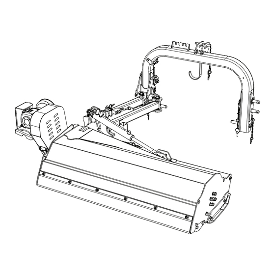
Page 36: Description Of The Parts
TECHNICAL CHARACTERISTICS Description of the parts 11 15 PTO shaft Lateral movement hydraulic jack Flail head orientation joint 3-point hitch Gearbox Boom support joint Pulleys Support foot Belts Lateral movement booms Rear guard Front guard Flail holder shaft Max pressure valve (optional) Flails Shredding flail head Support roller... -
Page 37: Technical Specifications
TECHNICAL CHARACTERISTICS Technical specifications TAB 1 Model ZMLE 1400 ZMLE 1600 Working width cm (in) 140 (55) 160 (63) Min. tractor width cm (in) 150 (59) 150 (59) Minimum/maximum tractor power HP (KW) 40/70 (30/52) 40/70 (30/52) Min. tractor weight Kg (lbs) 1600 (3527) 1700 (3748) PTO speed... -
Page 38: Noise Level
TECHNICAL CHARACTERISTICS Noise level The noise level produced is checked on all the models of machines produced by FERRI. The noise values indicated are emission levels and do not necessarily represent safe operational levels. The relationship between emission levels and exposure levels cannot be reliably used to establish whether further precautions are required or not. -
Page 39: Radius Of Work
TECHNICAL CHARACTERISTICS Radius of work The data relating to the width of cut covered by the machine are provided below. 3.6.1 Right coupling EXTERNAL RIGHT COUPLING INTERNAL RIGHT COUPLING TAB 2 ZMLE 1400 ZMLE 1600 2,39 2,59 7' 10" 8’ 6” 1,69 1,69 5’... -
Page 40: Left Coupling
TECHNICAL CHARACTERISTICS 3.6.2 Left coupling EXTERNAL LEFT COUPLING INTERNAL LEFT COUPLING TAB 2 ZMLE 1400 ZMLE 1600 1,21 1,41 3' 12" 4’ 8” 1,69 1,69 5’ 7” 5’ 7” 0,68 0,68 2' 3" 2’ 3” 0,74 0,94 2' 5” 3’ 1” 5' 11"... -
Page 41: Accessories
TECHNICAL CHARACTERISTICS Accessories 3.7.1 Flails Depending on the type of material to be cut, use the most appropriate flails. The following table lists the cutting flails that may be fitted to the machine and their respective characteristics. TYPE OF CUTTING FLAILS DESCRIPTION Multi-use “Y”... -
Page 42: Runners
TECHNICAL CHARACTERISTICS 3.7.2 Runners The runners (1) allow: Adjustment of the working height of the machine, in combination with the support roller (see Chapter 5); Prevent premature wearing of the cutting flails. ZMLE Rev. 2.0... -
Page 43: Controls With Distributor
TECHNICAL CHARACTERISTICS 3.7.3 Controls with distributor For tractors equipped with only one oil pressure tap or on specific demand by the customer, it is possible to fit a two lever control distributor (A) with flexible pipes, also envisaged with the float system for operating the hydraulic ram (1). - Page 44 TECHNICAL CHARACTERISTICS Page left intentionally blank ZMLE Rev. 2.0...
-
Page 45: Installation And Handling
TRANSPORT AND INSTALLATION INSTALLATION AND HANDLING Always wear safety footwear, overalls, safety gloves and, if necessary, earmuffs and a dust mask during use and during machine maintenance, repair, handling and storage operations. Lifting To lift the machine, use safety hooks and cables with a suitable lifting capacity, to be inserted only in the points indicated for lifting, identified by the decals applied on the machine. -
Page 46: Removal Of Packaging And Pre-Assembly
TRANSPORT AND INSTALLATION Removal of packaging and pre-assembly A special packaging is provided for machine transport, which requires some pre-assembly operations to be carried out before fitting the machine to the tractor. FOR SAFETY REASONS IT IS STRICTLY FORBIDDEN TO USE THE MACHINE IN CONDITIONS OTHER THAN THOSE RECOMMENDED. - Page 47 TRANSPORT AND INSTALLATION Remove the shaft, laid inside the machine frame and attached to it with metal ropes. Place it on a flat surface in a safe place so as to not hamper the assembly operations of the machine. Fasten the third point arc with a belt or chain of adequate capacity for lifting, before cutting the fastening metal wires applied.
- Page 48 TRANSPORT AND INSTALLATION Lift the machine with a lifting device/hoist of adequate capacity, removing it from the wooden box and lowering it slowly. With this type of hitch the machine tends to position itself horizontally, therefore lay it down carefully on the floor.
- Page 49 TRANSPORT AND INSTALLATION Proceed with the assembly of the machine. Open the booms of the machine using a lifting device and a suitable belt for lifting and attach both of them. Fix the booms in the hitch seat using the relative pin. Attach the three-point hitch of the machine.
- Page 50 TRANSPORT AND INSTALLATION Set the machine with right or left coupling. ► Right coupling: place the pin (2) on the right side of the three-point hitch. Insert the pin into the joint by means of a hoist (1). ► Insert the closing flange (5), the washer (4) and tighten the nut (3). 4.10 ZMLE Rev.
- Page 51 TRANSPORT AND INSTALLATION ► Fasten the hose support bracket (6) to the right hand side of the three-point hitch (7) passing the hoses (8) outside the arch. Tighten the screw (9) and the nut (10). 4.12 15) Lay the hydraulic hoses correctly passing them on the left boom and fixing them with the appropriate hose clamps, using as reference the distances provided in the figure.
- Page 52 Left coupling: the procedure is the same, bearing in mind that the hose support bracket (6) must be fastened to the three-point hitch so that the hoses pass inside the arch. 4.13 FERRI Srl declines all responsibility for damage caused by the incorrect assembly of the parts. CAUTION ZMLE Rev.
-
Page 53: Coupling To Tractor
TRANSPORT AND INSTALLATION Coupling to tractor Prior to coupling the machine to the tractor, make sure that: All the controls have been disabled; The tractor engine has been switched off; DANGER The parking brake has been applied; The ignition key has been removed from the dashboard; All moving parts have come to a complete stop. -
Page 54: Attaching Without A Quick Hitch
TRANSPORT AND INSTALLATION 4.3.1 Attaching without a Quick Hitch Move the 2 tractor hydraulic lifting device arms (1) towards the attachments of the machine so that (2) they overlap. Insert the lifting device arms into the attachments (2) and lock them with the safety (3) pins. Fit the third point stabiliser (4). -
Page 55: Hydraulic Connections For Lateral Movement
TRANSPORT AND INSTALLATION 4.3.3 Hydraulic connections for lateral movement Make sure that the hydraulic hoses are fitted and mounted correctly. If they are inverted this will cause movements opposite to those commanded. Connect the hydraulic hoses with quick hitch on the tractor after having checked that all attachments are clean and in optimum condition. -
Page 56: Fitting The Pto Shaft
TRANSPORT AND INSTALLATION Fitting the PTO shaft Before using the PTO shaft, carefully read the use and maintenance manual. PTO SHAFT SPECIFICATIONS No. Splines Fitting 1” 3/8 50 mm (2”) (MIN.) If the PTO shaft supplied with the machine is not being used, check that the cowlings of the machine and of the tractor are overlapped on the protection of the PTO shaft at least by the amount contemplated by the safety regulations in force (50 mm/1.97 in). - Page 57 TRANSPORT AND INSTALLATION Whenever the machine is being coupled to a tractor for the first time, you must observe the following instructions: ► In the condition of maximum steering, the PTO shaft must not be completely closed in order to avoid damage to the gearbox.
- Page 58 Be sure the coupling is locked in position. ► Always stop the power takeoff when lifting the tool or when the manoeuvring angles are too large. FERRI declines all responsibility for damage caused by incorrect assembly and use of the PTO transmission. CAUTION ZMLE Rev.
-
Page 59: Tractor Stability
TRANSPORT AND INSTALLATION Tractor stability Check the lifting capacity and the longitudinal stability of the tractor by means of the following formula. Add ballast at the front if necessary. To determine the total weight of the machine, add up the weight of all the components (see Chapter 3). 0,2 T 4.19 M x (s1+s2) ≤... -
Page 60: Detachment From The Tractor
TRANSPORT AND INSTALLATION Detachment from the tractor Proceed as follows to uncouple the machine from the tractor: Apply the tractor parking brake. Close the arms (for side shredders). Lower the machine support feet (if present) and lock them into place. Position the machine on the ground using the tractor hydraulic lifting device. -
Page 61: Adjustments
ADJUSTMENTS ADJUSTMENTS Always wear safety footwear, overalls, safety gloves and, if necessary, earmuffs and a dust mask during use and during machine maintenance, repair, handling and storage operations. Working speed adjustment Safe working speed depends on terrain condition, grass type to be cut, density, height of cut and the degree of chopping required. -
Page 62: Adjusting The Cutting Height
ADJUSTMENTS Adjusting the cutting height Position the tractor on flat ground in order to avoid lateral loading of the machine on the tie rods. Before adjusting, turn off the engine, put the hand brake on, disengage the power take-off and remove the ignition key. CAUTION Do not work or carry out maintenance operations or repairs under the machine or its components unless these are securely supported on blocks or supports, in order to... - Page 63 ADJUSTMENTS To perform adjustment of the runners (if present), proceed as follows on both sides of the flail head: Maintain the shredder in a horizontal position and lifted off the ground; Unscrew the screws (1) and the nut (3); Depending on the degree of finishing that you want to obtain, align one of the two holes (A,B) on the runner (2) with the hole on the frame;...
-
Page 64: Adjusting The Belt Tension
ADJUSTMENTS Adjusting the belt tension Position the tractor on flat ground in order to avoid lateral loading of the machine on the tie rods. Before adjusting, turn off the engine, put the hand brake on, disengage the power take-off and remove the ignition key. CAUTION Remove the protective casings from the belts (1 - 2);... -
Page 65: Use And Operating Rules
USE AND OPERATION USE AND OPERATING RULES Always wear safety footwear, overalls, safety gloves and, if necessary, earmuffs and a dust mask during use and during machine maintenance, repair, handling and storage operations. Controls Set the machine control levers inside the cab in an ergonomic position for the driver and fastened to a solid support on the tractor. -
Page 66: Positioning Of The Machine During Operation
USE AND OPERATION Positioning of the machine during operation To position the machine correctly during operation, proceed as follows: Make sure that there is sufficient space between the working range of the machine and other equipment and/ or things. Completely open tap (1) in position A to unblock the shredding flail head. In this way, using the controls in the cab, the operator can put the machine into working phase from the transport position with the flail head in a vertical position. -
Page 67: Starting
USE AND OPERATION Starting 6.3.1 Preliminary checks ► Make an overall visual inspection of the machine. ► Check the tightening of all the screws. ► Check the integrity of the guards. ► Check the level of oil in the transmission unit. ►... -
Page 68: Working Mode
USE AND OPERATION Working mode During use of the machine, there may be emission of dust. Use tractors with a cab with filters on the ventilation system, or use suitable systems to protect the airways, such as dust masks or masks with a filter. Operate the machine briefly and then check to see if the work performed is satisfactory. -
Page 69: Stopping
USE AND OPERATION Stopping Before stopping the tractor: Close the arms and lower the flail head to the ground; Disengage the rotor drive and wait till the rotor has completely stopped (approx. 30 sec.); Turn off the tractor, take the starting key out and apply the parking brake; If the ground is sloping, insert wedges to block the tractor wheels. -
Page 70: Mounting Position Changeover Procedure
USE AND OPERATION Mounting position changeover procedure Starting with the attachment mounted on the right hand side (A) of the three-point hitch (1) the attachment can be mounted on the left hand side (B) and vice versa. ZMLE Rev. 2.0... -
Page 71: Moving The Attachment From The Right Side To The Left Side
USE AND OPERATION 6.6.1 Moving the attachment from the right side to the left side Initial working position with the coupling on the right: The attachment is fastened to the right hand side of the three-point hitch (1) via the arms (2) and the joint (3). In the working position, the pins (4 and 5) are in the unlocked position. - Page 72 USE AND OPERATION To couple the attachment to the left hand side, proceed as follows: Place the head in a horizontal position. Insert the pin (7) in order to lock it horizontally. Insert the pin (6) in order to limit its leftwards movement. The locked position indicated in the figure refers only to the working position with the coupling on the left.
- Page 73 USE AND OPERATION Raise the machine slightly off the ground. Take the right support foot (8) and place it into the appropriate housing in the right arm (9). Leave the left foot (10) in its housing and in the raised position. Lower the machine and rest the head and the right foot (8) on solid level ground.
- Page 74 USE AND OPERATION Release the pin (11) by unscrewing the nut (12) using an open ended spanner (size 36) and remove the washer (13). Remove the closing flange (14) after having pushed the pin (11) by 20mm towards the inside of the three-point hitch.
- Page 75 USE AND OPERATION Disconnect the three-point hitch (1) from the joint (3) by lowering it slightly and moving the tractor forwards. The pin (11) should be removed from hole of the joint (3). Move the pin (11) from the right to the left coupling. Position the pin (11), making sure that the non-threaded part protrudes 15mm from the frame.
- Page 76 USE AND OPERATION Reverse the tractor towards the pin so that the joint (3) is aligned with the left side coupling. In order to couple the attachment to the machine, follow the procedure for removing it in reverse. There is a small hole in the head of the pin (11) that enables it to be rotated and inserted into the joint (3).
- Page 77 USE AND OPERATION Fasten the hose support bracket (15) to the left hand side of the three-point hitch (1) passing the hoses (18) inside the arch. Tighten the screw (17) and the nut (16). Connect the hydraulic hoses to the tractor. 6.13 Insert the pins (4 and 5) into the holes on the right hand side coupling of the three-point hitch (1).
-
Page 78: Moving The Attachment From The Left Side To The Right Side
USE AND OPERATION Raise the machine from the ground and place the right support foot into its housing on the three-point hitch in a raised position. Reinstall the PTO shaft. The attachment is now mounted in its working position with the coupling on the left. In this position, both the horizontal head-locking pin (7) and the leftward movement limit pin (6) must remain inserted. -
Page 79: Precautions For Transfers With The Attachment Mounted On The Left Side
USE AND OPERATION 6.6.3 Precautions for transfers with the attachment mounted on the left side Detach the shaft (19) from the PTO of the tractor and leave it connected to the gearbox. Reduce the shaft (19) to the minimum length and fasten it to the three-point hitch (1) using the relative support (20). -
Page 80: Transport Position
USE AND OPERATION Transport position 6.7.1 Transport position with coupling on the right For road transport it is necessary to: ► Place the machine as indicated in the following figure: ► Insert the following mechanical locks: floating device block (A) inserted; floating device block (B) inserted;... - Page 81 USE AND OPERATION 6.17 ZMLE Rev. 2.0...
-
Page 82: Transport Position With Coupling On The Left
USE AND OPERATION 6.7.2 Transport position with coupling on the left Detach the shaft (2) from the PTO (to allow the head to be lifted) and attach it to its support. WARNING For road transport it is necessary to: ► Place the machine as indicated in the following figure: ►... - Page 83 USE AND OPERATION 6.18 ZMLE Rev. 2.0...
- Page 84 USE AND OPERATION Page left intentionally blank ZMLE Rev. 2.0...
-
Page 85: Routine Maintenance
ROUTINE MAINTENANCE ROUTINE MAINTENANCE Always wear safety footwear, overalls, safety gloves and, if necessary, earmuffs and a dust mask during use and during machine maintenance, repair, handling and storage operations. General information The criteria for routine maintenance of the machine are provided below, based on the company’s experience and on advice received from our customers. -
Page 86: Checklist
ROUTINE MAINTENANCE Checklist The Checklist serves to schedule all the maintenance operations and to monitor the frequency with which they are performed in order to ensure the correct routine maintenance of the machine. The manufacturer recommends keeping the original document attached to the instruction manual, and creating personal copies for every authorised technician, to make a note of the interventions carried out on the machine. -
Page 87: Every 50 Working Hours Or Every Month
ROUTINE MAINTENANCE 7.2.2 Every 50 working hours or every month ► Check the tension and efficiency of the transmission belts (where fitted) ► Check the oil level of the tank or gearbox ► Visually check the machine to identify the presence of any breakages or damage ►... -
Page 88: Every 200 Working Hours
ROUTINE MAINTENANCE 7.2.3 Every 200 working hours ► Check the rotor flails are not worn ► Check the balancing of the rotor ► Check the conditions of the oil filter cartridge (outlet and inlet where fitted) ► Check the correct adjustment of the controls Intervention date Manager Intervention date Manager ZMLE... -
Page 89: Every 500 Working Hours Or Every Month
ROUTINE MAINTENANCE 7.2.4 Every 500 working hours or every month ► Replace the oil in the gearbox ► Replace the oil filter cartridge (outlet and inlet where fitted) ► Check the seal of the oil filling cap (if necessary replace) ►... -
Page 90: Oil Table
ROUTINE MAINTENANCE Oil table The following table lists the oils to be used for topping up the levels. TYPE CLASSIFICATION BLASIA 220 ISO VG 220 litres gallons 0,34 ZMLE 1400 OIL QUANTITY IN THE GEAR ZMLE 1600 0,34 ZMLE Rev. 2.0... -
Page 91: Greasing
ROUTINE MAINTENANCE Greasing LUBRICANT TYPE CLASSIFICATION AGIP GR MU EP/2 SAE90 ► Use a hand-held grease gun for all greasing. ► Wipe the grease nozzle with a clean dry cloth, to avoid injecting dirt and grit. ► Under particularly taxing work conditions, perform lubrication operations more frequently than the every 8 hours usually adopted. -
Page 92: State Of The Belts
ROUTINE MAINTENANCE State of the belts Check for correct belt tension every 50 hours. Replace the belts every 500 hours. CAUTION New belts If the belts are new, make the first check after 4 hours of work to check how they are settling and the degree of tension. -
Page 93: Fastening The Hydraulic Hose Couplings
ROUTINE MAINTENANCE Fastening the hydraulic hose couplings Check that the hydraulic hose couplings have been correctly fastened (TAB 2). TAB 2 Tightening torque Tightening torque Screw thread type MIN. N.m MAX. N.m 1” 1” 1/4 1” 1/2 Tightening torque table for the cylindrical screw thread GAS UNI ISO 228 1 83 - BSPP CAUTION TAB 3 Tightening torque... -
Page 94: Bolt Tightening
ROUTINE MAINTENANCE Bolt tightening Check that the bolts are correctly tightened (TAB 3). TAB 3 STANDARD DIN 10.9 12.9 new ► Pitch Pitch Pitch Pitch Pitch Pitch Pitch Ø ▼ M2.5 0,45 M3.5 1,25 1,25 1,75 1.008 1.041 1.004 1.098 1.204 1.317 1.181... - Page 95 ROUTINE MAINTENANCE SYMBOL MEANING Screw Hex head Large Fine The torque values reported in table 3 correspond to 80% of the yield stress limitIn each column two values are reported of which the first refers to a friction coefficient of 0.10 and the second to a coefficient of 0.14. For our applications it is advised to refer to the values corresponding to the coefficient of 0.14.
-
Page 96: Before Use Or Putting Into Service After A Long Peroid Of Inactivity
ROUTINE MAINTENANCE 7.8 Before use or putting into service after a long peroid of inactivity Before using the machine for the first time or after a long peroid of inactivity: ► Check that the machine is not damaged; ► Check that the mechanical parts are in good condition and free of rust; ►... -
Page 97: Parking Or Storage
ROUTINE MAINTENANCE 7.9 Parking or storage Whenever the machine will not be used for a long period of time, take the following measures to keep it in good condition and free of dust and rust. ► Detach the machine from the tractor (see Chapter 4). ►... - Page 98 ROUTINE MAINTENANCE Page left intentionally blank ZMLE Rev. 2.0...
-
Page 99: Extraordinary Maintenance
EXTRAORDINARY MAINTENANCE EXTRAORDINARY MAINTENANCE Always wear safety footwear, overalls, safety gloves and, if necessary, earmuffs and a dust mask during use and during machine maintenance, repair, handling and storage operations. Before carrying out any type of maintenance: Wait until all moving parts come to a complete stop; Lower the machine to ground level;... -
Page 100: Belt Replacement
EXTRAORDINARY MAINTENANCE Belt replacement For ZMLE: Remove the protective casings from the belts (1 - 2); Remove the guard (3); Loosen the 4 nuts (4) that lock the gearbox; Proceed on the tensioner (5); Move the pulley consequently reducing the belt tension; Remove the belts (6) from the respective pulley wheels and replace them with new ones;... -
Page 101: Pulley Replacement
EXTRAORDINARY MAINTENANCE Pulley replacement The pulleys are fixed to their relative shafts using a taper bush (1). To disassemble the pulley proceed as follows: Loosen the screws (2) with the appropriate wrench; Remove the screws (2) and insert them in the threaded holes (3) tightening uniformly; After a few turns of the screws the pulley should be extracted easily from the shaft. -
Page 102: Pipe Replacement
EXTRAORDINARY MAINTENANCE Pipe replacement Any intervention or maintenance on the hydraulic system has to be carried out by specifically instructed personnel. WARNING ► Before working on the hydraulic system, release all residual pressure, working with the engine off and using all the control levers. -
Page 103: Pin Replacement
EXTRAORDINARY MAINTENANCE Pin replacement Carry out this operation by means of a lifting device or hoist, to avoid parts that are not fixed from falling or causing a loss of balance. When replacing parts, clean and grease their housing. ZMLE Rev. -
Page 104: Rotor
The rotor shaft has already been electronically balanced: If a flail has to be replaced, change the whole set. Fitting non-original flails causes vibrations or the breakage of the rolling bearings. To replace damaged parts or flails, contact the specialised personnel of the FERRI Assistance Service or authorised dealers. -
Page 105: Guards
EXTRAORDINARY MAINTENANCE Guards Always check the general condition (integrity, fixing, etc.) of the guards. Guards which are deformed, damaged or not fixed correctly, do not guarantee the working safety for which they have been designed. IF THE INSTRUCTIONS ARE NOT OBSERVED, THE USER WILL BE CONSIDERED LIABLE DANGER FOR ANY AND ALL CIVIL AND/OR CRIMINAL DAMAGE THAT MAY BE CAUSED. -
Page 106: Flail Replacement
When replacing the flails, DO NOT REMOVE THE BALANCING WEIGHTS from their original position. WARNING If irregularities or strange noises are noticed after changing the flails, contact FERRI immediately. WARNING Replace bent or broken flails with new flails. For safety reasons, never attempt to straighten the flails or to perform welding on them because this can reduce their strength. -
Page 107: Trouble Shooting Chart
9.1 Trouble shooting chart The maintenance operations authorised by FERRI srl are the ones indicated in Chapter 7 – “ROUTINE MAINTENANCE”. The content of this chapter is not exhaustive. Instead, it aims to provide information on the most common problems in order to help specialised technicians to find the fault in question. - Page 108 Loose bolts nuts if necessary Have the frames repaired at Excessive machine Machine with cracks or initial signs authorised Ferri workshops. operating noise of breakage Check to see if there are any moving parts unbalanced and correct the defect Worn bearings...
- Page 109 Broken, worn or missing flails Replace the flails Check rotor balancing and have repairs Unbalanced flail holder shaft or replacements made in authorised Ferri workshops Worn flail holder shaft bearings Have it replaced in specialised workshops Identify the part responsible for the problem...
- Page 110 TROUBLE SHOOTING PROBLEMS PROBABLE CAUSE REMEDIES Excessive material to chop Reduce advance speed Get an authorised FERRI workshop to check the Hydraulic system requires checking state of the filter, the hydraulic pipes, the setting of the valves etc. Hydraulic oil overheating (over 80°C)
- Page 111 Check the condition of the joints, seals, Oil leakage onto the motor and hoses (especially for drainage). Replace if clogged or damaged Repair or replace the pump at authorised Ferri Pump worn-out or damaged workshops. Check the condition of the discharge filter and replace if necessary...
- Page 112 TROUBLE SHOOTING PROBLEMS PROBABLE CAUSE REMEDIES Adjust the number of tractor PTO rpm Manoeuvre speed not suitable Adjust the manoeuvre speed of the function Irregular arm involved by means of adjustable choke (if operation present). Otherwise, contact an authorised workshop Air present inside hydraulic circuit Bleed the air from inside the circuit Check motor operation.
-
Page 113: Scrapping And Disposal
SCRAPPING AND DISPOSAL 10 SCRAPPING AND DISPOSAL If the machine is to be scrapped, it must be disposed of in suitable waste disposal sites in accordance with the regulations in force. In the case of demolition of the machine, all parts that could constitute a hazard must be made safe. Recover any old oil and dispose of it in special oil disposal centres. - Page 114 SCRAPPING AND DISPOSAL Page left intentionally blank ZMLE Rev. 2.0...
-
Page 115: Warranty
At the moment of delivery, check that the machine and the disassembled accessories have not been damaged by transport or handling. Any complaints must be sent in writing to FERRI within 8 (eight) days of the date of receiving the machine, enclosing description of machine... - Page 116 WARRANTY Page left intentionally blank ZMLE Rev. 2.0...
-
Page 117: Optional Units
OPTIONAL UNITS 12 OPTIONAL UNITS Always wear safety footwear, overalls, safety gloves and, if necessary, earmuffs and a dust mask during use and during machine maintenance, repair, handling and storage operations. Before carrying out any type of maintenance: Wait until all moving parts come to a complete stop; Lower the machine to ground level;... -
Page 118: Adjustable Lateral Runners
OPTIONAL UNITS 12.1 Adjustable lateral runners The runners (1) protect against the rapid wear of knives. They are fitted laterally to the side of the shredder with the support of M12 screws (2), washers (3) and nuts (4) positioned in the way indicated in the figure. Height adjustment should be carried out simultaneously with the support roller (see Chapter 5). -
Page 119: Hydraulic Safety Device Kit
OPTIONAL UNITS 12.2 Hydraulic safety device kit If during work the machine comes into contact with a strong body, the shredder moves automatically by means of a maximum pressure valve (1) connected to the hydraulic jack (A), to prevent serious damage to the structure of the machine. - Page 120 OPTIONAL UNITS 12.3 Controls with distributor For tractors equipped with only one oil pressure tap or on specific demand by the customer, it is also possible to fit a hydraulic ram control distributor provided with a float system to control the shredder’s orientation. 12.3.1 Assembly procedure Screw or seal the plate (1) to the three-point coupling in the indicated position.
- Page 121 OPTIONAL UNITS Screw the reduction couplings (5) with the relative sealing washers. Disassembly the four quick hitches (4) from the hoses and install them on the supply hoses (6). Replace properly the two unused quick hitches. CAUTION 12.5 Screw the four reduction couplings to the distributor with the relative sealing washers. Connect the pipes (7) to the distributor as indicated in the figure.
- Page 122 OPTIONAL UNITS Page left intentionally blank ZMLE Rev. 2.0...
- Page 123 NOTES...
- Page 124 FERRI s.r.l. Via C. Govoni, 30 44030 Tamara (FE) - ITALY Tel/Phone: 39-0532.866866 Fax: +39-0532.866851 http://www.ferrisrl.it e-mail: info@ferrisrl.it FERRI FRANCE Plaine de FONTGRAVE 81800 RABASTENS Tél. 05 63 40 84 00 Fax 05 63 40 84 08 http://www.ferri-france.fr e-mail: contact@ferri-france.fr...
Need help?
Do you have a question about the ZMLE Series and is the answer not in the manual?
Questions and answers