Table of Contents
Advertisement
WARNING: Do Not Operate Before Reading Manual
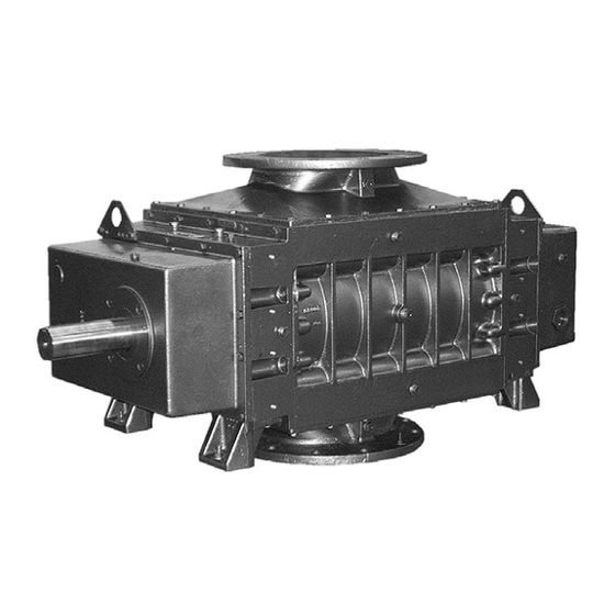
Mechanical Vacuum Boosters
OPERATOR'S MANUAL
Models
9012
9027
9016
9036
9020
31/35/90/92 Series - Vertical Flow
33/37/91/93 Series - Horizontal Flow
All rights reserved. Product information and specifications subject to change.
Tuthill Springfield
Tuthill
Mechanical Vacuum Boosters
Copyright © 2020 Tuthill Springfield
|
tuthillvacuumblower.com
Manual 2001 Rev B p/n 2001
|
800.825.6937
Advertisement
Table of Contents
Troubleshooting

Related Manuals for Tuthill M-D Pneumatics 9000 Series

Summary of Contents for Tuthill M-D Pneumatics 9000 Series
- Page 1 Mechanical Vacuum Boosters OPERATOR’S MANUAL Models 9012 9027 9016 9036 9020 31/35/90/92 Series - Vertical Flow 33/37/91/93 Series - Horizontal Flow Copyright © 2020 Tuthill Springfield All rights reserved. Product information and specifications subject to change. Tuthill Springfield tuthillvacuumblower.com 800.825.6937...
-
Page 2: Table Of Contents
TABLE OF CONTENTS SECTION PAGE 1. INTRODUCTION 1.1 APPLICABLE DOCUMENTATION 1.2 SCOPE OF MANUAL 2. CONVENTIONS AND DATA PLATE 2.1 GRAPHIC CONVENTIONS IN MANUAL 2.2 DATA PLATE 3. LIFTING 4. DESCRIPTION 4.1 FLOW DIRECTION BY ROTATION 4.2 SPECIFICATIONS 5. INSTALLATION 5.1 GENERAL 5.1.1 LOCATION 5.1.2 FOUNDATION... -
Page 3: Introduction
1. INTRODUCTION CONGRATULATIONS on your purchase of a new Mechanical Vacuum Booster from Tuthill Springfield. Please examine the booster for shipping damage, and if any damage is found, report it immediately to the carrier. If the booster is to be installed at a later date make sure it is stored in a clean, dry location and rotated regularly. -
Page 4: Data Plate
2.2 DATA PLATE MAWP YEAR Tuthill Vacuum & Blower Systems MAX RPM 4840 West Kearney Street Springfield, Missouri USA 65803 READ INSTRUCTION MANUAL BEFORE OPERATION OR BODILY HARM MAY RESULT... -
Page 5: Lifting
Refer to diagrams in this manual for proper rotation and orientation in inlet and discharge. Tuthill Springfield model 9000 mechanical vacuum boosters are positive displacement type units, whose pumping capacity is determined by size, operating speed, and differential pressure conditions. Vacuum boosters employ rotors rotating in opposite directions within a housing closed at the ends by end plates. -
Page 6: Flow Direction By Rotation
Consult your Tuthill Springfield sales professional if questions arise. 4.1 FLOW DIRECTION BY ROTATION... -
Page 7: Installation
NOTE Specially ordered blowers with nonstandard construction, or with rotor end clearances greater than shown within the Assembly Clearances table, will not have the operating limits specified here. Contact your Tuthill Springfield sales representative for specific information. NOTE Special attention must be paid when a vacuum booster has a higher than standard ambient suction temperature. - Page 8 WARNING The bare shaft booster can generate excessive noise. Methods to reduce the noise levels by installing inlet and outlet silencers will be required. Even with inlet and outlet silencers, hearing protection will be required. WARNING Customers are warned to provide adequate protection, warning and safety equipment necessary to protect personnel against hazards in the installation and operation of this equipment in the system or facility.
-
Page 9: Location
A booster may be driven by direct-coupling to the driver or by V-belt drive, to obtain other speeds within approved range. (See the Motor Drives section for more information.) Boosters from Tuthill Springfield are internally and externally treated after factory assembly and testing to protect against rusting in normal atmospheric conditions prior to installation. The maximum period of internal protection is considered to be up to 6 months under average conditions, provided closing plugs and seals are not removed. -
Page 10: Soft Foot
Repeat steps 4 and 5 on remaining feet. 5.2 SAFETY Tuthill Springfield recommends the use of relief valves to protect against excessive pressure or vacuum conditions. These valves should be tested at initial start-up to be sure they are properly adjusted to relieve at or below the maximum pressure differential rating of the booster. -
Page 11: Lubrication
5.3 LUBRICATION Every booster from Tuthill Springfield is factory tested; oil drained and shipped dry to its installation point. Both oil reservoirs must be filled to the proper level before operation. In addition to the splash lubrication, booster series incorporating pressure lubrication with a integral oil pump, pressure relief valve, filter and oil-to-coolant heat exchanger. -
Page 12: Filling Procedure
5.3.1 FILLING PROCEDURE See Figure 4. Recommended lubricants are shown on page 32. 1. Remove large hex head fill plug from back (non-drive) end cover. 2. SLOWLY pour oil through fill until oil appears in the oil sight glass. Bring oil level to center of sight glass. 3. -
Page 13: Hazards Associated With Breakdown Or Ignition Of Lubrication
PER 40 CAUTION Factory supplied filters are engineered to provide the proper restriction in the oil lubrication system. Using filters other than those available from Tuthill Springfield may result in lubrication problems and possibly unwarrantable damage to the booster. 5.3.6 OIL PRESSURE ADJUSTMENT... -
Page 14: Oil Cooler
5.3.7 OIL COOLER The supply line to the cooler can be connected to either hole. The fluid flowing through the heat exchanger should be sufficient to keep the oil temperature to the optimum operating range of 150-180 °F (65-80 °C). This temperature will insure proper lubrication of the bearings and seals. -
Page 15: Motor Drives
5.5 MOTOR DRIVES Two drive connections commonly used are direct drive and V-belt drive. 5.5.1 DIRECT COUPLED When installing the motor directly to the booster, align shafts to coupling in accordance with the coupling manufacturer’s instructions. Boosters shipped with motor directly coupled and mounted on a common base have been aligned prior to shipment and normally no further alignment is necessary. - Page 16 SETTING V-BELT TENSION Proper belt tension is essential to long booster life. The following diagrams and procedures are provided to aid in field adjusting V-belts Too Tight (when booster is so equipped) for maximum Too Tight performance. A visual inspection of the V-belt drive should yield the appearance shown in Slight Bow Too Loose...
-
Page 17: V-Belt Troubleshooting
5.5.3 V-BELT TROUBLESHOOTING PROBLEM POSSIBLE CAUSES SOLUTION Belts slip (sidewalls glazed) Not enough tension Replace belts; apply proper tension Shock load Apply proper tension Drive squeals Not enough arc of contact Increase center distance Heavy starting load Increase belt tension Broken cord caused by prying on sheave Replace set of belts and install correctly Overloaded drive... -
Page 18: Operation
6. OPERATION 6.1 GENERAL DANGER The booster is not intended to be used with explosive products or in explosive environments. WARNING Do not operate without guards in place. WARNING Maximum operating speed: Table 1 states the maximum operating speed in RPM (rotations per minute) and maximum temperature. Do not exceed these limits. -
Page 19: Start-Up Checklist
6.2 START-UP CHECKLIST We recommend that these startup procedures be followed in sequence and checked off ( ) in the boxes provided in any of the following cases: • During initial installation • After maintenance work has been performed • After any shutdown period •... -
Page 20: Stopping
WARNING Physical harm may occur if human body parts are in contact or exposed to the process vacuum. Assure that all connections are protected from human contact. WARNING If rated vacuum or pressure levels are exceeded, process fluids will migrate to other parts of the booster and system. -
Page 21: Shutdown
However, due to the wide variations in mineral content, pH, and chemical content of water that can be injected, Tuthill Springfield cannot be responsible for damage which may result should this build-up occur. Units should be inspected regularly to determine any problems. -
Page 22: Maintenance
7. MAINTENANCE 7.1 GENERAL Regular inspection of your vacuum booster and its installation, along with complete checks on operating conditions will pay dividends in added life and usefulness. Also, service the drive per manufacturer’s instructions and lubricate the coupling or check belt drive tension. By use of thermometers and gauges, make sure that booster operating temperature and pressure remain within allowed limits. -
Page 23: Spare Parts
Major repairs not covered in this book should be referred to the nearest Tuthill Springfield service representative. When ordering parts, give all booster nameplate information, as well as the item number and parts description as per the parts lists and assembly drawings for your particular model. -
Page 24: Long Term Storage
Tuthill Corporation on any unit being returned for any reason which has been handling or involved with hazardous gases or materials. This is for the protection of the employees of Tuthill Corporation who are required to perform service on this equipment. Failure to do so will result in service delays. -
Page 25: Disassembly And Assembly
8. DISASSEMBLY AND ASSEMBLY 8.1 DISASSEMBLY 1. Drain lubricant from free end cover (7) by removing magnetic drain plug (31) or (1 08). Disconnect or remove the external oil lines, oil filter, and heat exchanger if applicable. Port fittings (38) may also be removed. -
Page 26: End Plate And Rotor Disassembly
Be sure they are in place. It is recommended that the gear end rotor shaft bearings be purchased from Tuthill, as they are specially ground to locate the rotors with correct end clearance relative to the gear end plate. -
Page 27: Free End Assembly
housing (3) in place, being sure dowel pins are installed. Do not bolt at this time. 4. Lay two pieces of 1/8” thick shims on the end plate at the bottom of the housing, parallel to the two rotor shaft bores. Set each rotor into position in the housing, with the gear end (long shaft) up. Face keyways in the direction shown in Figure 8. -
Page 28: Adjusting Interlobe Clearance
8.2.4 ADJUSTING INTERLOBE CLEARANCE LONG FEELER GAUGE RECORD A-A READING HERE 18. The outer gear shell is fastened to the RECORD B-B inner hub with four cap screws and located READING HERE with two dowel pins. Adding or removing shims between the gear shell and the inner hub moves the gear shell axially. - Page 29 same tool used for sleeve and secure with both set screws. c. Press bearing (362) into bearing carrier (447). Lubricate journal and install on mounting bracket using four screws (321) alternately to draw the carrier into place. d. Press bearing (362) into bearing carrier (447). Lubricate journal and install on mounting bracket using four screws (321) alternately to draw the carrier into place.
-
Page 30: Troubleshooting
9. TROUBLESHOOTING Although Tuthill Springfield boosters are well designed and manufactured, problems may occur due to normal wear and the need for readjustment. The chart below lists symptoms that may occur along with probable causes and remedies. SYMPTOM PROBABLE CAUSE... -
Page 31: Assembly Clearances
10. ASSEMBLY CLEARANCES Values shown in inches and millimeters. GEAR END FREE END INTERLOBE TIP-DOWEL MODEL TIP-PORT .007 - .010 .010 - .015 .013 - .018 .009 - .013 .013 - .018 9012 .18 - .25 .25 - .38 .33 - .46 .23 - .33 .33 - .46 .007 - .010... -
Page 32: Recommended Lubricants
12. RECOMMENDED LUBRICANTS RECOMMENDED LUBRICANTS FOR Tuthill offers oils that are suitable for a wide range of operating temperatures that are based TUTHILL BLOWER AND VACUUM on model, operating speed and discharge BOOSTERS temperature of the product. Tuthill positive displacement blowers and... - Page 33 MD BLOWER & BOOSTER LUBRICANTS SPECIFICATIONS: PRODUCTS MD ONE MD PLUS MD MAX MD FG VISCOSITY INDEX @40°C, CST 99.1 231.7 340.9 99.3 @100°C, CST 14.4 27.6 37.2 13.9 FLASH POINT 510 (266) 480 (249) 491 (255) 515 (268) °F (°C) POUR POINT - 44 (-43) -49 (-45)
-
Page 34: Special Tool Drawings
13. SPECIAL TOOL DRAWINGS FIGURE 13 — FIGURE 14 — LABYRINTH SEAL INSTALLATION TOOL BEARING INSTALLATION TOOL ROD-M10P1.5 × 175MM LG 6.300 2.750 69.85 3.070 2.990 6.140 Ø 4.915 FIXTURE 5.980 4.910 2.250 PLATE 90° 124.841 57.15 124.714 4 HOLES 3/4”... -
Page 35: Parts Lists And Assembly Drawings
PARTS LIST FOR MODEL 9000 VACUUM BOOSTERS ITEM ITEM PART DESCRIPTION 90/91 92/93 31/33 35/37 PART DESCRIPTION 90/91 92/93 31/33 35/37 140 O-RING ROTOR 174 PIPE PLUG HOUSING 176 O-RING END PLATE 195 LIFTING LUG DRIVE END COVER 196 CAP SCREW*** FREE END COVER 197 SPACER —... - Page 39 PARTS LIST FOR MODEL 9000 BOOSTERS WITH SUBMERGED OIL PUMP ASSEMBLY ITEM PART DESCRIPTION 31/33 35/37 103 HOSE CLAMP 108 MAGNETIC PLUG LOCKWASHER 122 SET SCREW 125 MOUNTING BRACKET 136 LOCKWASHER 144 OIL PUMP 150 HOSE 166 BARBED CONNECTION 175 PIPE NIPPLE 258 ELBOW 273 BARBED CONNECTION 306 SHAFT SLEEVE...
- Page 40 ASSEMBLY DRAWING FOR MODEL 9000 BOOSTERS WITH SUBMERGED OIL PUMP ASSEMBLY...
- Page 41 NOTES:...
-
Page 42: Warranty - Blower Products
WARRANTY – BLOWER PRODUCTS Subject to the terms and conditions hereinafter set forth and set forth in General Terms of Sale, Tuthill Springfield (the Seller) warrants products and parts of its manufacture, when shipped, and its work (including installation and start-up) when performed, will be of good quality and will be free from defects in material and workmanship. -
Page 43: Operating Data Form / Product Registration
NOTES: IMPORTANT All blowers manufactured by Tuthill Springfield are date coded at time of shipment. In order to assure you of the full benefits of the product warranty, please complete, tear out and return the product registration card, or register online at tuthillvacuumblower.com. - Page 44 VACUUM & BLOWER SYSTEMS 4840 West Kearney Street TUTHILL CORPORATION Springfield, Missouri USA 65803-8702 O 417.865.8715 800.825.6937 F 417.865.2950 Manual 2001 Rev B p/n 2001 tuthillvacuumblower.com 1/20 Copyright © 2020 Tuthill Springfield All rights reserved. Product information and specifications subject to change.
Need help?
Do you have a question about the M-D Pneumatics 9000 Series and is the answer not in the manual?
Questions and answers