Advertisement
Quick Links
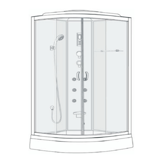
900 Quadrant Steam
This product is IPX4 rated, and so no part of the installation
Shower Cabin with 6 Body Jets
is allowed to be within bathroom Zones 0 or 1. Installation is
permitted within Zone 2
and outside of the bathroom zones as long as it is not in a
PLEASE READ THE GUIDE BEFORE COMMENCING INSTALLATION
position where it is likely to be sprayed with water.
Zone 0: The interior of the bathtub or shower basin.
Zone 1: The area around the bathtub or shower basin
up to a height of 2.25m above the floor
Zone 2: The area stretching to 0.6m outside the bath or
shower and above the bath or shower if over 2.25m
Please retain this document for future reference
Multiple person assembly
BUY IT DIRECT
Lowfields Way
Elland
Hx5 9DA
Advertisement

Related Manuals for Better Bathrooms 900 Quadrant Steam

Summary of Contents for Better Bathrooms 900 Quadrant Steam
- Page 1 900 Quadrant Steam This product is IPX4 rated, and so no part of the installation Shower Cabin with 6 Body Jets is allowed to be within bathroom Zones 0 or 1. Installation is permitted within Zone 2 and outside of the bathroom zones as long as it is not in a PLEASE READ THE GUIDE BEFORE COMMENCING INSTALLATION position where it is likely to be sprayed with water.
- Page 2 Information Parts (Electrical work to be carried out by a Qualified Electrician) > This installation is a multiple person installation > Ensure the glass is not chipped or cracked before installation > AC Power supply of 220V + 10% 50 Hz which should be connected to to an earthed 13amp fused spur switch, outside the bathroom.
- Page 3 Parts Tray Install ! Check for removal of any protective film/tape Waste Waste Pipe Before installatiing the tray, connect the waste pipe (X) and fixing ring to the waste body, once connected tighten the ring using the screw. Place the tray inc waste into the required location Once in position check the tray is level If levelling is required, adjust the legs on the tray Check the tray using a spirit level...
- Page 4 Install (Multiple person assembly) Install 1. Connect the top and bottom rails (1) to the fixed panels (2) 4. Push seal (N) onto the edge of the fixed panel (2) 2. Hold the rail (1) to the front face of the chrome profile (2) 5.
- Page 5 Install (Multiple person assembly) Install 8. You must seal the frame as shown below, along the length of the 9. Attach the top and bottom covers (M) to the end of the touching surfaces (Do not seal on the inside) central panel (5) 10.
- Page 6 Install (Multiple person assembly) Install 15. Remove assembly, drill holes using 5.2mm drill bit (supplied) 12. Place the panel assembly onto the tray and align frame with tray. 13. Place the steel plate (V) onto the back corner of the tray (Drill should not be on hammer setting) 14.
- Page 7 Install (Multiple person assembly) Install 17. Place the front frame and glass onto the tray and align on the 18. Seal the frame as shown, before connecting the front frame to the tray and with the back panels, drill frame using a 3mm drill bit. back panels and to the tray.
- Page 8 Install (Multiple person assembly) Install 19. Place the roof (6) onto the assembly and secure to the frame using 21. Secure the steam generator frame to the steel plate (V) using fixings provided nuts and bolts (G) 20. Connect flexi-tube from mixer to shower head connection, 22.
- Page 9 Install (Multiple person assembly) Install 23. To connect the mixer to the water supply, you will require 27. Seal the outside of the enclosure, along the front edge 2 x flexi connectors with 1/2" female nut (not supplied) where any touching surfaces meet. 24.
- Page 10 Install (Multiple person assembly) Install 30. Connect handset holder (K) to the left hand back panel 35. Fit fixed roller (J1) to top of each glass door, secure and fit tighten and secure using fixings (D), do not overtighten cover 31.
- Page 11 Install (Multiple person assembly) Cable Connections (Cont) 39. Offer the handle up to the pre-formed holes in the doors The clips are colour coded ie blue to blue, red to red. 40. Join the handles through the glass and secure using the They are also labelled with symbol indicators.
- Page 12 Layout diagram and symbols Control Panel Function Please note Telephone function requires connection to your landline cable connector CD function requires connection to a CD player with the CD player outside the enclosure SEPT 18 - V6BB...
- Page 13 Control Panel Function Control Panel Function Power Button Radio Station Storage Press the Power button to activate the control panel, the top When the radio is on and you have found the station required light will come on press the M button to store this station When the radio is on press and hold the M button, the radio will search for available stations, press M to store Top Light...
- Page 14 Control Panel Function Safety, Alarms and Error Messages Steam Function The control panel is installed with 4 malfunction messages Press the steam button to activate the steam, the symbol will appear on the display Issue Steam generator does not shut down when set temperature is reached Steam Adjustment Issue...
-
Page 15: Turn Off Water Supply
Aftercare Aftercare In the event that your product has a problem some maintenance may be required. Dripping head, hand shower or body jets when mixer OFF Fig 1 Fig 2 Some dripping may occur after the mixer is turned off, this is expected due to drainage. - Page 16 Aftercare Aftercare In the event that your product has a problem some maintenance may be required. Fig 2 Fig 1 Temperature control issue If the temperature control does not regulate the temperature once the product is installed this could be due to incorrect pressures. This could be due to debris in the thermostat, as the system was not flushed prior to connection of the water supply.
- Page 17 Aftercare Guarantee Certain parts included within this product are covered by a 12 month When using or cleaning the product, do not spray direclty for any period of time guarantee: at the drainage slots in the tray. Handset Thermostat Bulbs Doing this could cause excess water to fill the slot and spill over the tray.
- Page 18 This appliance should not be used by persons with a lack of experience, knowledge or without understanding in the use of the appliance in a safe way At Better Bathrooms we can accept your old WEEE when you and understands the hazards of improper use.
Need help?
Do you have a question about the 900 Quadrant Steam and is the answer not in the manual?
Questions and answers