Table of Contents
Advertisement
Chapter 1
Introduction
An Overview of Network 9000 Product Features...............................................11
C h a s s i s . . . . . . . . . . . . . . . . . . . . . . . . . . . . . . . . . . . . . . . . . . . . . . . . . . . . . . . . . . . . . . . . . . . . . . . . . . . . . . . . . . . . . . . . . 1 2
S l o t s a n d M o d u l e s . . . . . . . . . . . . . . . . . . . . . . . . . . . . . . . . . . . . . . . . . . . . . . . . . . . . . . . . . . . . . . . . . . . . . . . . . . . . . 1 2
P o w e r S u p p l i e s . . . . . . . . . . . . . . . . . . . . . . . . . . . . . . . . . . . . . . . . . . . . . . . . . . . . . . . . . . . . . . . . . . . . . . . . . . . . . . . . . 1 3
T h e M i d p l a n e . . . . . . . . . . . . . . . . . . . . . . . . . . . . . . . . . . . . . . . . . . . . . . . . . . . . . . . . . . . . . . . . . . . . . . . . . . . . . . . . . . 1 3
C o n t r o l S t o r a g e . . . . . . . . . . . . . . . . . . . . . . . . . . . . . . . . . . . . . . . . . . . . . . . . . . . . . . . . . . . . . . . . . . . . . . . . . . . . . . . . 1 3
Type 1 and Type 2 Communication Options . . . . . . . . . . . . . . . . . . . . . . . . . . . . . . . . . . . . . . . . . . . . . . . 1 4
Managing Network 9000 Products...............................................................14
C o n t r o l P o i n t . . . . . . . . . . . . . . . . . . . . . . . . . . . . . . . . . . . . . . . . . . . . . . . . . . . . . . . . . . . . . . . . . . . . . . . . . . . . . . . . . . . 1 4
S N M P . . . . . . . . . . . . . . . . . . . . . . . . . . . . . . . . . . . . . . . . . . . . . . . . . . . . . . . . . . . . . . . . . . . . . . . . . . . . . . . . . . . . . . . . . . . 1 5
The DECnet Network Control Program (NCP)............................................15
The DEC Terminal Server Manager (TSM) Utility......................................15
Managing Modules and Power Supplies with Common Commands........................16
Managing Links Midplane Ethernet Segments...............................................16
The Link Map . . . . . . . . . . . . . . . . . . . . . . . . . . . . . . . . . . . . . . . . . . . . . . . . . . . . . . . . . . . . . . . . . . . . . . . . . . . . . . . . . 1 8
Managing Initialization Records...............................................................19
Viewing Chassis Management Characteristics...............................................19
S u m m a r y . . . . . . . . . . . . . . . . . . . . . . . . . . . . . . . . . . . . . . . . . . . . . . . . . . . . . . . . . . . . . . . . . . . . . . . . . . . . . . . . . . . . . . . . . . . 1 9
Chapter 2
Logging on to the Command Interface of a Processor Module................................21
Using the CHASSIS CONSOLE SLOT command..............................................22
E n t e r i n g C o m m a n d s . . . . . . . . . . . . . . . . . . . . . . . . . . . . . . . . . . . . . . . . . . . . . . . . . . . . . . . . . . . . . . . . . . . . . . . . . . . . . . 2 3
Abbreviating Commands and Keywords . . . . . . . . . . . . . . . . . . . . . . . . . . . . . . . . . . . . . . . . . . . . . . . . . . 2 3
Specifying Slot Lists ..........................................................................23
4
Table of Contents
0020
Advertisement
Table of Contents

Subscribe to Our Youtube Channel
Related Manuals for Xyplex Network 9000


Summary of Contents for Xyplex Network 9000
-
Page 1: Table Of Contents
Introduction An Overview of Network 9000 Product Features..........11 C h a s s i s ..................1 2 S l o t s a n d M o d u l e s . - Page 2 Specifying Power Supply Numbers ............2 4 Editing the Command Line .
- Page 3 Inhibiting a Processor Module ............. . 1 0 6 Resetting or Inhibiting a Power Supply............106 [DEFINE SERVER] RESET CHASSIS HOLD..........108 Appendix A Network 9000 Type 1 and Type 2 Options Appendix B Status and Error Messages Glossary...
- Page 4 Figures A Six-Slot Network 9000 Chassis............11 A Fifteen-Slot Network 9000 Chassis.............12 Midplane Ethernet Segment Configuration 1 ......... . . 1 7 Midplane Ethernet Segment Segment Configuration 2 .
- Page 5 Tables Xyplex Login Prompts..............21 Editing Characters ............... . . 2 4 Network Identifiers .
-
Page 6: Preface
This manual describes how to use the Xyplex Network 9000 chassis management ™ commands to change and monitor certain characteristics of Network 9000 product modules and power supplies. It also explains the commands that display and monitor these characteristics. The Network 9000 chassis management commands manage the characteristics of products while they are operational, after they have loaded software and parameters. - Page 7 Symbol Means Press the New Line, Carriage Return <CR>, or Enter key on your terminal's keyboard. This is the Xyplex prompt at Secure and Nonprivileged ports. Xyplex> This is the Xyplex prompt at Privileged ports. Xyplex>> In examples, this manual uses This typeface to show your entry.
-
Page 8: An Overview Of Network 9000 Product Features
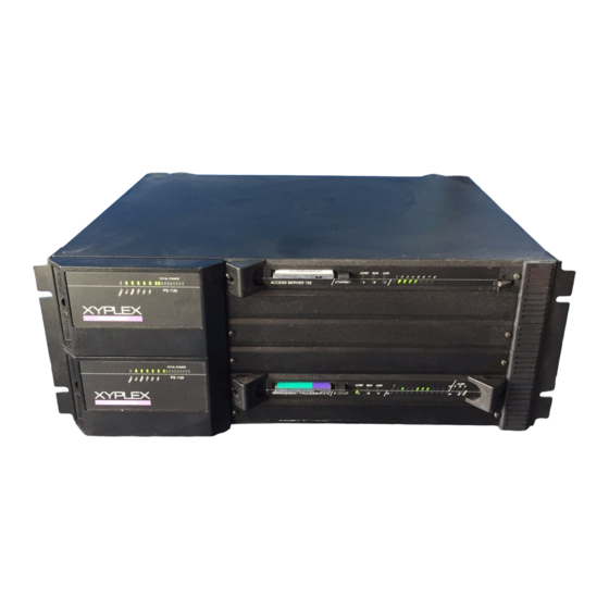
Figure 1-1 shows a Network 9000 chassis with six slots and compartments for two power supplies. Figure 1-2 shows a Network 9000 chassis with fifteen slots and compartments for five power supplies. -
Page 9: A Fifteen-Slot Network 9000 Chassis
10BASE-T Concentrator 201 consists of an I/O module only. The Network 9000 Intra-Networking Hub also offers an adaptor card, which allows you to use Xyplex MAXserver family products in a Network 9000 chassis. If you currently use MAXserver products, you can still use them as part of a Network 9000 Intra-Networking Hub. -
Page 10: C O N T R O L S T O R A G
Introduction Power Supplies The Network 9000 power supply system is designed so that you can add power supplies as your network needs grow. Some configurations permit you to configure power supplies for redundancy and "hot-swapping," to ensure a constant supply of power to the modules in the chassis. -
Page 11: Type 1 And Type 2 Communication Options
Managing Network 9000 Products Network managers can use a variety of software tools to manage Network 9000 products. Some of these tools are supplied by Xyplex. Other tools are supplied by vendors such as Digital Equipment Corporation, Sun Microsystems, Inc., etc. -
Page 12: The Decnet Network Control Program (Ncp)
DECnet software. You use the NCP utility at a VMS host to manage the operation of the Xyplex units . This utility is described in the documentation supplied by DEC. Refer to the Master Index supplied with your release of VMS software for more information. -
Page 13: Managing Modules And Power Supplies With Common Commands
The connection between a Network 9000 module and either a midplane Ethernet segment or an external network is called a l i n k. Different Network 9000 products have varying numbers of links, and you can change the link connections with a chassis management command. -
Page 14: Midplane Ethernet Segment Configuration 1
Introduction Network 9000 Chassis Midplane Ethernet Segments Concentrator Sales Concentrator Accounting Concentrator Manufacturing External LAN Bridge/Router Figure 1-3. Midplane Ethernet Segment Configuration 1 The LAN bridge/router has three Ethernet links, and in this example each one connects to a different midplane segment. The fourth link on the LAN bridge/router provides a connection to an external LAN. -
Page 15: The Link Map
The combination of links on a Network 9000 product to either midplane Ethernet segments or external networks is called a link map. Each Network 9000 product has a default link map which also supports optional connections. Chapter 3 describes the default link map of managed concentrators, terminal servers, LAN bridge/routers, and WAN bridge/routers in detail. -
Page 16: Managing Initialization Records
9000 module or PS/130 power supply. For example, from the Network 9000 module in slot 2, you can display the status of the Network 9000 module in slot 4 or a PS/130 power supply. The remaining chapters of this manual explains how to log on to a Network 9000 processor module and use the chassis management commands. -
Page 17: Entering Chassis Management Commands
Chapter 2 Entering Chassis Management Commands This chapter explains how to log on to the command interface of a processor module and enter the chassis management commands. This chapter includes the following sections: • Logging On to the Command Interface of a Processor Module •... -
Page 18: Logging On To The Command Interface Of A Processor Module
Return key until one of the Xyplex login prompts appears, shown in Table 2-1. Connection from the Network: If your terminal is connected to a Xyplex Type 1 or Type 2 product on the network, use the TELNET CONSOLE or REMOTE CONSOLE commands to log on to the command interface of the processor module. -
Page 19: Using The Chassis Console Slot Command
Type 2 module in the chassis, you can enter the following command: Xyplex>> chassis console slot 6 One of the Xyplex login prompts in Table 2-1 will appear on the screen. Enter a username or password, depending on the type of prompt which appears. 0020... -
Page 20: E N T E R I N G C O M M A N D
Xyplex>> The Privileged prompt includes a double carrot (>>) rather than a single carrot (>). Note: Xyplex recommends that you change the default Privilege password on all processor modules in the chassis to ensure the security of your network. The Software Management Guide for each product describes how to change the Privilege password. -
Page 21: Specifying Power Supply Numbers
Xyplex - 1919 - Slot x is empty The variable x indicates a slot number. This message can also appear if either a MAXserver family card or a Network 9000 Type 1 product exists in the slot. The SHOW/MONITOR [SERVER] CHASSIS SUMMARY command displays the status of each chassis slot. -
Page 22: Editing Characters
Entering Chassis Management Commands Table 2-2. Editing Characters Key Sequence Function <CTRL> <A> Alternates between insert character mode and overstrike character. Oversrike mode is the default. This function does not apply to hardcopy terminals. <CTRL> <B> Recalls the previous command. or up arrow key ↑... - Page 23 The following example shows how to use the command line recall and editing features. Suppose that you enter the following command, which contains a typographical error: Xyplex> shw parameter server The software will not accept SHW as a valid command. Instead of retyping the whole command line, however, you use the up-arrow key or <CTRL><B>...
-
Page 24: T E L N E T C O N S O L
Log on to a remote console port through the Internet The TELNET CONSOLE command allows you to log on to the console port (port 0) of a Network 9000 Type 1 or Type 2 product, or a MAXserver product, through Telnet. - Page 25 Xyplex> telnet console 117.29.10.30 Enter Username> 2. This example uses a domain name with the TELNET CONSOLE command: Xyplex> telnet console host.financesun.xyplex.com Enter Username> 3. This example uses a domain name with a Telnet port number: Xyplex> telnet console host financesun.xyplex.com:2000 0020...
-
Page 26: R E M O T E C O N S O L
LED on the processor module remains lit whenever a session is active on the console port. If you do not see the Xyplex login prompt when you connect to the console port, press the Return key once or twice until the prompt appears. After you have logged on to the console port, you can enter any Xyplex command that the product supports. - Page 27 2. This command uses the same node name as in example 1, and includes a maintenance password. Xyplex>> remote console node ts720 maint password "9c" 3. This command uses the Ethernet address of the remote server and a maintenance password.
-
Page 28: Chassis Console Slot
CHASSIS CONSOLE SLOT Connect to another processor module in the chassis The CHASSIS CONSOLE SLOT command establishes a connection to the Xyplex command interface on any Network 9000 Type 2 processor module in the chassis through the local management bus (LMB). Notes The console port in the target slot cannot have an active session. - Page 29 Entering Chassis Management Commands Enter a username and press the Return key. When you enter a valid username, the Xyplex> prompt appears and you can enter Xyplex commands. Xyplex> End of Chapter 0020...
-
Page 30: Managing The Operational Link Map
Chapter 3 Managing the Operational Link Map The operational link map determines the connections between the links on a Network 9000 module and either the midplane Ethernet segments or an external LAN or WAN. This chapter explains the default and optional connections on Type 2 modules and how to change them. -
Page 31: The Link Map For A Managed Concentrator 210
Figure 3-1 shows the network map for a managed concentrator with a model 202 10BASE-T Concentrator I/O module, which includes 24 ports, an AUI (LAN) link, and a FOIRL (fiber optic) link. Midplane Ethernet Segments in a Network 9000 Chassis Repeater Ports Twisted Pair 1 Twisted Pair 2... -
Page 32: A Show Chassis Slot Status Display For A Managed Concentrator
A. To change the connection to segment B or C, you can enter a command such as the following, which specifies segment B: Xyplex>> define chassis slot ethernet repeater 1 segment b Xyplex>> The link map looks like the one in Figure 3-3 after the change. -
Page 33: A Sample Link Map For A Managed Concentrator
Managing the Operational Link Map Midplane Ethernet Segments in Repeater Ports a Network 9000 Chassis Twisted Pair 1 Twisted Pair 2 Managed Concentrator Twisted Pair 24 FOIRL Figure 3-3. A Sample Link Map for a Managed Concentrator 0020... -
Page 34: The Link Map For A Terminal Server 720
A Terminal Server 720 has one Ethernet link which can connect to any one of the three midplane Ethernet segments. Figure 3-4 shows the link map for a Terminal Server 720 with the default and optional connections. Midplane Ethernet Segments in a Network 9000 Chassis Terminal Server Ethernet Link 1 Default... - Page 35 B: Xyplex>> define chassis slot ethernet 1 segment b XYPLEX - 1901-WARNING-This command will change the ethernet segment NOW! Press <Return> to modify parameter, any other key to abort. Xyplex>> The link map looks like the one in Figure 3-6 after the change.
-
Page 36: A Sample Link Map For A Terminal Server With A Lan Bridge/Router
Figure 3-6 shows the terminal server with the Ethernet link to segment B, and a LAN bridge/router with an Ethernet link to segment B. The LAN bridge/router provides access to the external LAN for the Ethernet link of the terminal server. Midplane Ethernet Segments in a Network 9000 Chassis External LAN Terminal Server Bridge/Router Figure 3-6. -
Page 37: The Link Map For A Lan Bridge/Router 410
Ethernet segments or to an external LAN. The fourth Ethernet link connects to an external LAN only. Figure 3-7 shows the link map for a LAN bridge/router 410 with the default and optional connections. Midplane Ethernet Segments in a Network 9000 Chassis External LANs Bridge/Router Ethernet Links E1-E4... - Page 38 LAN. For example, these commands connect Ethernet 2 to external LAN 2, and Ethernet 3 to external LAN 3: Xyplex>> define chassis slot link ethernet 2 external Xyplex>> define chassis slot link ethernet 3 external...
- Page 39 The LAN bridge/router connects link 2 to external 2, and link 3 to external 3. The link map looks like the one in Figure 3-9 after the change. Midplane Ethernet Segments in a Network 9000 Chassis External LANs Bridge/Router Ethernet Links E1-E4 Figure 3-9.
-
Page 40: The Link Map For A Wan Bridge/Router 460
Ethernet link can connect to any one of the midplane Ethernet segments or an external LAN. The WAN links connect to external WANs only. Figure 3-10 shows the link map for a WAN Bridge/Router 460 with the default and optional connections. Midplane Ethernet Segments in a Network 9000 Chassis External LAN Bridge/ Router WANs... - Page 41 Managing the Operational Link Map Figure 3-11 shows the Chassis Slot Status display for a WAN bridge/router in slot 5 with the default settings in the Link Mappings Section of the display. Slot 5 Status: Operational Firmware Version: 410000 Processor Module: BR/460 Proc Mod.
-
Page 42: A Sample Link Map For A Wan Bridge/Router 460 With A Lan Bridge/Router
The WAN bridge/router automatically associates the link with the correct external LAN. For example, this command connects Ethernet 1 to segment B: Xyplex>> define chassis slot link ethernet 1 segment b The software automatically connects the Ethernet link to segment B. The link map looks like the one in Figure 3-12 after the change. - Page 43 Change a connection in the link map The DEFINE [SERVER] CHASSIS SLOT command changes the link connection on a managed Network 9000 module, such as a managed concentrator, a terminal server, a LAN bridge/router, or a WAN bridge/router to either a midplane Ethernet segment or an external LAN.
- Page 44 (You cannot abbreviate this phrase to ETHERNET num to change segments on a managed concentrator.) Table 3-1 shows the network identifiers available for each Network 9000 Type 2 product. Table 3-1. Network Identifiers identifier...
- Page 45 Managing the Operational Link Map Table 3-2 shows the selections available for each Network 9000 Type product. Table 3-2. Network Selections selection Managed Terminal W A N Concentrators Servers Bridge/Routers Bridge/Routers SEGMENT A, SEGMENT A, SEGMENT A, B, or C...
- Page 46 2. The following command specifies a connection to midplane Ethernet segment B for the link on a terminal server. Xyplex>> define chassis slot link ethernet 1 segment B XYPLEX-1901-WARNING-This command will change the ethernet segment NOW! Press <Return> to modify parameter, any other key to abort.
- Page 47 4. The following command specifies an external connection for the Ethernet link on a WAN bridge/router. Xyplex>> define chassis slot link Ethernet 1 external Other valid versions of this command are the following: Xyplex>> define chassis slot ethernet 1 external Xyplex>>...
-
Page 48: Managing Initialization Parameters
Chapter 4 Managing Initialization Parameters The chassis management commands in this chapter provide an alternate way of changing parameters in initialization records if you do not do so through the initialization configuration menu. The Getting Started Guide for each product describes how to use the initialization configuration menu. -
Page 49: The Status Of The Initialization Record
Table 4-1 shows the default status for the initialization records on each Network 9000 product. Initialization records have values for all parameters, whether they are enabled or disabled. -
Page 50: Link Selection
A processor module uses this connection while loading and dumping over the network. The Link Selection in Figure 4-1 is Ethernet 1 Segment A, which is the default for the primary initialization record on all Network 9000 processor modules. -
Page 51: Enabling And Disabling Protocols
Segment A. Enabling and Disabling Protocols By default, a Network 9000 module obtains its software load image and parameters from a flash memory card. If a flash card is not present, the module requests the software load image and parameter file from the flash card of another module in the chassis, or one or more hosts on the network. - Page 52 XMOP as a software load image protocol in the primary initialization record for the terminal server in slot 2: Xyplex>> define chassis slot 2 load primary image protocol xmop disabled The syntax of the command that enables or disables dump protocols is the following:...
-
Page 53: Using The Card, Xmop, And Mop Protocols
The Xyplex Maintenance Operations Protocol (XMOP) looks for the files on the flash card of another Network 9000 processor module in the chassis, or a Xyplex loader on the network. The Software Installation Guide for Xyplex Loader Kits contains information about Xyplex loaders, Network 9000 flash memory cards, and XMOP. -
Page 54: Using The Bootp And Rarp Protocols
2: Xyplex>> define chassis slot 2 load primary software XPCSRV20 Using the BOOTP and RARP Protocols The Bootstrap Protocol (BOOTP) and the Reverse Address Resolution Protocol (RARP) look for the software load image and parameter file names on a UNIX host. - Page 55 Figure 4-1 shows 0.0.0.0 in this field, because that is the default. The following is an example of the command which specifies an Internet address in the primary initialization record of the terminal server in slot 2: Xyplex>> define chassis slot 2 load primary internet address 140.180.118.2 Internet Load Host The Internet load host specifies the Internet address of the host on the network where the software load image file resides.
-
Page 56: Resetting Initialization Parameters To Default Values
Internet Load File in the primary initialization record of the terminal server in slot 2: Xyplex>> define chassis slot 2 load primary internet file "/usr/xyplex/images/xpcsrv20.sys" Resetting Initialization Parameters To Default Values... -
Page 57: Define [Server] Chassis Slot Dump Protocol
TERTIARY The PRIMARY initialization record is the default. protocol One of the following protocols or the keyword ALL: Protocol Means XMOP Xyplex MOP Protocol Digital Equipment Corporation Maintenance Operations Protocol BOOTP Bootstrap protocol RARP UNIX Reverse Address Resolution Protocol All protocols ENABLED Enable the protocol on the processor modules in the slots you specify. - Page 58 5. Because PRIMARY is the default record type, the command line does not include it. Xyplex>> define chassis slot 5 dump protocol bootp enabled 2. This example disables MOP as a dump protocol for the secondary initialization record for the processor module in the local slot.
-
Page 59: Define [Server] Chassis Slot Load Internet Address
Managing Initialization Parameters DEFINE [SERVER] CHASSIS SLOT LOAD INTERNET ADDRESS Specify the Internet address of a processor module for DTFTP loading The DEFINE [SERVER] CHASSIS SLOT LOAD INTERNET ADDRESS command specifies the Internet address of the module or module set in the slot you specify for DTFTP loading. - Page 60 Managing Initialization Parameters Example This example specifies an Internet address for the processor module in slot 6. Xyplex>> define chassis slot 6 load internet address 150.169.70.133 Xyplex>> 0020...
-
Page 61: Define [Server] Chassis Slot Load Internet [Load] Gateway
The Internet address of the gateway. address Example This example specifies an Internet address for the gateway used by a LAN bridge/router in slot 6 to gain access to the load host. Xyplex>> define chassis slot 6 load internet gateway 150.122.30.164 Xyplex>> 0020... -
Page 62: Define [Server] Chassis Slot Load Internet [Load] File
Managing Initialization Parameters DEFINE [SERVER] CHASSIS SLOT LOAD INTERNET [LOAD] FILE Specify the software load image filename for DTFTP loading The DEFINE [SERVER] CHASSIS SLOT LOAD INTERNET [LOAD] FILE command specifies the pathname and name of the file that contains the software load image on the Internet host you specify for DTFTP loading. - Page 63 Enclose the pathname and filename in quotes. Example This example specifies the pathname and file name that contains the software load image for a bridge in slot 6. Xyplex>> define chassis slot 6 load internet file "/usr2/br/1.2/xprr2.sys" Xyplex>> 0020...
-
Page 64: Define [Server] Chassis Slot Load Internet [Load] Host
Managing Initialization Parameters DEFINE [SERVER] CHASSIS SLOT LOAD INTERNET [LOAD] HOST Specify the Internet address of the load host for DTFTP loading The DEFINE [SERVER] CHASSIS SLOT INTERNET [LOAD] HOST command specifies the Internet address of the host where the software load image resides. - Page 65 Managing Initialization Parameters Example This example specifies an internet address for the load host that contains the software load image for the terminal server in slot 6. Xyplex>> define chassis slot 6 load internet host 150.122.30.155 Xyplex>> 0020...
-
Page 66: Define [Server] Chassis Slot Load Protocol
Notes By default, a Network 9000 module attempts to obtain the software load image and parameter file from a flash card using the CARD protocol. If a card is not present, the module attempts to obtain these files using other protocols in this order: XMOP, MOP, BOOTP, RARP, DTFTP. - Page 67 4. (Enabling this protocol requires that you specify DTFTP information with the DEFINE CHASSIS SLOT LOAD INTERNET commands.) Xyplex>> define chassis slot 4 load primary image protocol dtftp enabled Xyplex>> 2. This example enables MOP as the protocol to use when loading the parameter file from the primary initialization record of the local router in slot 5.
- Page 68 3. This example disables the RARP protocol for use when loading the parameter file from the secondary initialization record of the terminal server in the local slot. Xyplex>> define chassis slot 4 load secondary parameters protocol rarp disabled Xyplex>> 0020...
-
Page 69: Define [Server] Chassis Slot Load Software
Managing Initialization Parameters DEFINE [SERVER] CHASSIS SLOT LOAD SOFTWARE Specify the CARD/XMOP/MOP file name of the software load image The DEFINE [SERVER] CHASSIS SLOT LOAD SOFTWARE command specifies the CARD/XMOP/MOP filename that contains the software load image. Notes You specify this filename if CARD, XMOP, or MOP is enabled as a load protocol for the software load image, and the load image name is different from the default. - Page 70 Managing Initialization Parameters Example This example specifies XPCSRV20 as the filename for the secondary initialization record on the terminal server in slot 4. Xyplex>> define chassis slot 4 load secondary software XPCSRV20 Xyplex>> 0020...
-
Page 71: Define [Server] Chassis Slot Loaddump Link
You cannot change the link selection with this command on managed concentrators. You can change the link selection through the initialization configuration menu, product-specific commands, or SNMP. See the manual Managing the Xyplex Ethernet Repeaters for more information about these product-specific commands. Privilege... - Page 72 Where sid is A, B, or C, and represents a midplane Ethernet segment. EXTERNAL Where EXTERNAL specifies an external LAN. When you specify EXTERNAL, the bridge or router automatically associates the Ethernet link with the correct external LAN. Table 4-6 shows the options available for each Network 9000 product. 0020...
- Page 73 Reinitialize the terminal server for this command to take effect. 2. The following command specifies the link selection for the secondary initialization record on a LAN bridge/router in slot 5 of the chassis. Xyplex>> define chassis slot 5 loaddump secondary link E1 segment b Xyplex>>...
-
Page 74: Define [Server] Chassis Slot Loaddump Enabled|Disabled
Managing Initialization Parameters DEFINE [SERVER] CHASSIS SLOT LOADDUMP ENABLED | DISABLED Enable or disable an initialization record The DEFINE [SERVER] CHASSIS SLOT LOADDUMP ENABLED | DISABLED command disables or enables an initialization record. Notes Not all initialization records are enabled by default on every product. Managed concentrators and terminal servers have only the primary initialization record enabled. - Page 75 I/O module first attempts to load or dump using information in the secondary initialization record. Xyplex>> define chassis slot 5 loaddump primary disabled Xyplex>> 2. The command in this example enables all initialization records for the managed concentrator in the local slot.
-
Page 76: Define [Server] Chassis Slot Loaddump Default
LAN bridge/routers , and WAN bridge/routers. The first sections of this chapter list the default settings for the initialization parameters of each Network 9000 product. Certain initialization records on some products are disabled by default. The secondary and tertiary initialization records on a managed concentrator or a terminal server, for example, are disabled by default. - Page 77 2 to its default settings. Because the secondary initialization record on a terminal server is disabled by default, this command also disables the initialization record. Xyplex>> define chassis slot 2 loaddump secondary default Xyplex>> The default settings for the secondary initialization record on a terminal...
- Page 78 Chassis Management Displays The chassis management commands in this chapter display and monitor characteristics of the chassis, the Network 9000 modules in chassis slots, the power supplies, and the initialization records. SHOW and LIST commands display current information about the modules and power supplies.
- Page 79 Chassis Management Displays • SHOW | MONITOR PARAMETER SERVER This display shows detailed information about a parameter server. • SHOW|MONITOR [SERVER] CHASSIS SLOT LMB COUNTERS This display shows diagnostic information about counters on the local management bus (LMB). These counters a mainly useful for troubleshooting, not normal status. 0020...
- Page 80 Syntax SHOW | MONITOR [SERVER] CHASSIS SUMMARY Display The following command produces the chassis summary display: Xyplex> show chassis summary Chassis Type: Network 9000 Rev 0 Base 802.x Address: 08-00-87-00-4F-A0 Backplane Serial #: 2324252627 Status: No Fault Number of Slots:...
- Page 81 The number of a chassis slot. Status A summary of the status of each Network 9000 module or module set, or Type 1 product in the slot. For more detailed information about the status of a module or module set, see the Show Chassis Slot Status display, described in this chapter.
- Page 82 Reset button once, or a user issued a RESET CHASSIS SLOT HOLD command for the module in this slot. Init Menu The Network 9000 processor module is running the initialization configuration menu. ROM Wait The processor module failed to obtain the software load image using the information in the enabled initialization records, although this information may be valid.
- Page 83 Chassis Management Displays Field Means Processor The hardware type and serial number of the Network 9000 processor Module module. If a Type 1 product is present in this slot, Unknown appears in this field. I/O Module The hardware type and serial number of the I/O module. If a MAXserver card is present in this slot, AC/119 or MX/101 appears in this field.
- Page 84 Chassis Management Displays SHOW/MONITOR [SERVER] CHASSIS POWER SUMMARY Display the summary information about power provided and power consumed The SHOW/MONITOR [SERVER] CHASSIS POWER SUMMARY command displays the total wattage that each PS/130 power supply in the chassis provides, the actual power consumed, and the estimated wattage that each slot in the chassis consumes.
- Page 85 Chassis Management Displays Field Means Hardware The hardware type of each power supply. Voltage levels The theoretical rating of the maximum power for each voltage level. The +5V +12V -12V total of these individual rated values may exceed the maximum rated total of the power supply.
- Page 86 One or more power supply numbers between 1-5, or the keyword ALL to indicate all PS/130 power supplies. Display This sample display shows the status for power supply number 2. Xyplex> show chassis power supply 2 status Power Supply 2 Type: PS/130 Serial #: 1234567890...
- Page 87 Chassis Management Displays Field Means Power Supply: The number of the power supply shown in this display. Status: The current state of the power supply. Possible states are these: Required This power supply must be available to support the modules in the chassis.
- Page 88 Chassis Management Displays Field Means Power The fields in this section show the maximum, actual, and available power generated at each voltage level on this power supply. The values in these fields represent the following information: Maximum: This is a theoretical rating of the maximum power for each voltage level.
- Page 89 One or more chassis slot numbers in the range of 1-15, or the keyword ALL to indicate all chassis slots. The local slot is the default. Display This sample display shows the status for a LAN bridge/router in slot 3. Xyplex> show chassis slot 3 status Slot 3 Status: Operational Firmware Version:...
- Page 90 The Network 9000 processor module is receiving the software load image. Parameters The processor module has requested the parameter file from Requested a parameter server. Parameter The Network 9000 processor module is loading its parameter Loading file. Dump The Network 9000 processor module has requested dump Requested service from a dump server.
- Page 91 If the module in the slot returns the status Not Responding, wait 30 seconds and enter the Slot Status command for the module in this slot again. If the module still returns the status Not Responding, contact your Xyplex representative. Processor...
- Page 92 Chassis Management Displays Field Means I/O Module The serial number on the I/O module. Serial # SCM Version The version of the Single Chip Microcontroller (SCM). Uptime The amount of time that has elapsed since the processor module was last reset.
- Page 93 Chassis Management Displays LIST/MONITOR [SERVER] CHASSIS SLOT LOADDUMP CHARACTERISTICS Display initialization record information The LIST/MONITOR [SERVER] CHASSIS SLOT LOADDUMP CHARACTERISTICS command displays the initialization parameters in the initialization records you specify. Privilege List/Nonprivileged Monitor/Privileged Level Syntax LIST|MONITOR [SERVER] CHASSIS SLOT [list | ALL] LOADDUMP [record|ALL] CHARACTERISTICS Where Means...
- Page 94 Chassis Management Displays Xyplex> list chassis slot 3 loaddump primary characteristics Primary Record: Enabled Link Selection Ethernet 1 Segment A Internet Load Address 140.179.80.133 Internet Load Host 140.179.119.3 Internet Load Gateway 0.0.0.0 Internet Load File /usr/xyplex/images/xpcsrv20.sys Software: XPCSRV20 Image Load Protocols Enabled: Card, XMOP, MOP, BOOTP, RARP, DTFTP...
- Page 95 Privilege Show/Nonprivileged Monitor/Privileged Level Syntax SHOW | MONITOR PARAMETER SERVER Display This sample display shows a parameter server for a terminal server: Xyplex> show parameter server Check Timer: Parameter Server Limit: Retransmit Timer: Parameter Servers: Retransmit Limit: Rejected Servers: Chassis Parameter Status:...
- Page 96 Chassis Management Displays Field Means Chassis A status that indicates whether or not this host is sending parameters to a Parameter module in the chassis. Current indicates that all parameters are up-to- Status date. Other status messages indicate that a parameter update is being attempted or is in progress.
- Page 97 Chassis Management Displays Field Means Default This message indicates that the processor module is using a set of default Parameters parameters. Used Name The name of the currently used parameter server. Address The address of the currently used parameter server. The current version number of the parameter file on the parameter Version server.
- Page 98 Show/Nonprivileged Monitor/Privileged Level Syntax SHOW|MONITOR [SERVER] CHASSIS SLOT LMB COUNTERS Display The following is a sample LMB counters display: Xyplex> show chassis slot lmb counters Local Management Bus Counters Messages Sent : Messages Received: Transmit Errors: Receive Errors: Xmit/Rcv Conflicts:...
- Page 99 Chassis Management Displays Field Means Xmit/Rcv. The number of I/O conflicts which occurred because the processor module Conflicts attempted to send and receive messages simultaneously. Invalid The number of times the processor module did not transmit a message Transmit because it was running diagnostics, or was in an invalid state for some State other reason.
- Page 100 Chassis Management Displays Field Means Receive The number of times the processor module did not receive an entire Fragment fragment of a message. Errors Abnormal The number of times the processor module was in an idle state, while the Receive End Single Chip Microcontroller (SCM) was in a receive state.
- Page 101 Network 9000 processor module in the chassis: [DEFINE SERVER] RESET CHASSIS device [# ] [HOLD] This command allows you to reset or inhibit (HOLD) a Network 9000 Type 2 processor module or a redundant PS/130 power supply from a remote location, because you do not have to physically press the Reset button on a processor module or turn off the power supply.
-
Page 102: A Chassis Summary Display For A Six-Slot Chassis With Two Power Supplies
The status of the module can indicate certain activities that you would not want to interrupt. Figure 6-1 is a sample Chassis Summary display for a six-slot chassis. Chassis Type: Network 9000 Rev 0 Base 802.x Address: 08-00-87-00-4F-A0 Backplane Serial #: 2324252627... - Page 103 When the process is complete, the user interface displays a welcome message, such as the one in this example, and prompts you to log on: Welcome to the Xyplex Terminal Server Enter Username> The log-on banner and prompt on your system may be different.
- Page 104 Resetting or Inhibiting Processor Modules and Power Supplies The RESET CHASSIS POWER SUPPLY HOLD command is equivalent to turning off the power supply. Doing this shuts off the power supply until you issue a RESET CHASSIS POWER SUPPLY command. You can only inhibit a redundant power supply. If you specify a required power supply, the command resets the processor on the power supply, but does not inhibit it.
-
Page 105: A Sample Power Supply Status Display
Inhibiting a Power Supply The following command holds power supply 2, which is Redundant. Xyplex>> reset chassis power supply 2 hold Power supply 2 is now inhibited, and is no longer providing power to modules in the chassis. Because it was redundant, one or more other power supplies in the chassis are now providing more power to compensate for the loss of power supply 2. - Page 106 Resetting or Inhibiting Processor Modules and Power Supplies [DEFINE SERVER] RESET CHASSIS [HOLD] Reset or inhibit a processor module or power supply The [DEFINE SERVER] RESET CHASSIS [HOLD] command resets or inhibits (holds) a processor module or a PS/130 power supply. Notes When you reset a processor module, it runs diagnostic programs, and reloads software and parameters.
- Page 107 After a short time, system initialization messages appear on the screen to indicate that the reset has occurred. 3. This example inhibits a redundant power supply 4. Xyplex>> reset chassis power supply 4 hold This command resets the power supply in slot 4. Xyplex>> reset chassis power supply 4 Power supply 4 can now provide power to modules in the chassis.
- Page 108 Type 1 and Type 2 Options Network 9000 Type 1 Options The following are Network 9000 Type 1 options. In addition to the products listed here, all MAXserver family products are Type 1 options. Type 1 options do not support chassis management commands, and connect to midplane Ethernet segment A only.
- Page 109 Network 9000 Type 1 and Type 2 Products Network 9000 Type 2 Options The following are Network 9000 Type 2 products which support chassis management commands, and can connect to midplane Ethernet segment A, B, or C. Ethernet Concentrators 210 Management Processor...
- Page 110 You attempted to change a link to either a midplane Ethernet segment or an external connection that was not valid for that link with a DEFINE CHASSIS SLOT command. See Chapter 3 for the valid link connections on each Network 9000 Type 2 product. 1915...
- Page 111 Slot x is empty The slot you specified in the command line does not contain a module, or it contains either a Network 9000 Type 1 product or a MAXserver family card. The variable x indicates a chassis slot number.
- Page 112 Messages 1931, 1932, 1933, and 1934 appear when a request to update parameters in the initialization record of a target slot fails for some reason. The problem may exist in the control of the target slot. If these messages continue to appear, contact your Xyplex representative.
- Page 113 I/O modules, and compartments for power supplies and the AC input module. Two types of Network 9000 chassis are available: a six-slot chassis with compartments for two power supplies and a fifteen-slot chassis with compartments for five power supplies.
- Page 114 If it is enabled, the processor module can use it to obtain initialization parameters. I/O module An I/O module is a Network 9000 component that provides links to the network and cabling. Terminal servers, LAN bridge/routers, WAN bridge/routers, and managed concentrators consist of a processor module and an I/O module. Unmanaged 10BASE-T concentrators consist of an I/O module only.
- Page 115 The midplane is a hardware component in the middle of the Network 9000 chassis. It connects the processor module and the I/O module of a Network 9000 product. Independent I/O modules also plug into the midplane. The midplane supports three internal Ethernet segments, four Token Ring Segments, and two FDDI segments.
- Page 116 A power supply is a component of the Network 9000 chassis which supplies power to the modules in the chassis. The Network 9000 chassis supports two types of power supplies: model PS/130 managed power supplies and model PS/120 unmanaged power supplies.
- Page 117 Ethernet segment A only. type 2 option A type 2 option consists of a Network 9000 module or module set. Type 2 options support chassis management commands and have l i n k s that can connect to midplane Ethernet segment A, B, or C.
Need help?
Do you have a question about the Network 9000 and is the answer not in the manual?
Questions and answers