Table of Contents
Advertisement
Quick Links
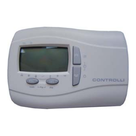
OmniaPRO Room Temperature Sensor
Models
Room temperature sensor with display and connecting cable
STA60L
with JST (2 m) connector
Room temperature and humidity sensor with display and
STA61L
connecting cable with JST (2 m) connector
APPLICATION AND USE
STA60L/61L sensors are respectively temperature and tem-
perature/humidity sensors which can be used combined with
W560 and OmniaPRO controllers.
TECHNICAL CHARACTERISTICS
Frontal protection:
Housing:
max. overall dimensions:
Analogue input
Room temperature
- operation
- storage
Room humidity
- operation and storage
Consumption
Supply
USER'S INTERFACE
The device is provided with a user's interface composed by:
•
4 buttons on the frontal panel (Fig. 1)
•
a 4-digit number display to visualize hours and labels of
menu, parameters and alarms
•
a 2-digit and a half number display + a temperature/humi-
dity visualization symbol (Fig. 2).
Fig. 1
Fig. 2
FUNCTIONS AND ICONS
The functions of the buttons and the meaning of the icons pre-
sent on the display are referred to the functions of the cotroller
W560; in case the sensor is used with WPRO controllers, fun-
ctions could be different.
In the following table you can see a description of the functions
associated to the icons of the display.
1st Issue
ISO 9001
Description
IP30
white ABS plastic;
137x96.5x31.3mm Lxhxb
(wall mounting)
1 NTC configurable (on board)
1 NTC/ 4...20mA / remote D.I.
configurable
-5T60°C
-10T70°C
10...90%RH
1W max
12Vdc from controller
03/12
CONTROLLI S.p.A.
16010 SANT'OLCESE Genova - Italy
Tel.: +39 01073061
E-mail: info@controlli.eu
Icon
ON
Heating mode
Cooling mode
Stand-by
<IMG INFO>
Dehumidifi cation
Economy
Alarm
<IMG INFO>
25,7
18,95
Time slot
Menu
IMG INFO
The display allows also to identify the operation mode of the
controller and the state of zone valve and circulating pump
through an arrow which indicates one of the following symbols
visible on the device:
Icon
1
Fax: +39 0107306870/871
Web: www.controlli.eu
STA60L/61L
Blinking ON
Remote heating mode
Remote cooling mode
Remote stand-by
Manual dehumidifi cation on
Confi gurable from parameter
Alarm paid off
Time slot operation enabled
/
Description
zone valve
water zone pump
mixing zone valve
economy + dynamic set point
Heat request
cool request
Heat integration
DBL362e
Advertisement
Table of Contents

Summary of Contents for Controlli OmniaPRO STA60L
- Page 1 In the following table you can see a description of the functions associated to the icons of the display. 1st Issue 03/12 DBL362e CONTROLLI S.p.A. 16010 SANT’OLCESE Genova - Italy Tel.: +39 01073061 Fax: +39 0107306870/871 ISO 9001 E-mail: info@controlli.eu...
- Page 2 MECHANICAL MOUNTING WIRING CONNECTIONS The sensors are designed for wall mounting. Operate on the connection when the device is not electrically Open the front panel of the device separating it from the bot- supplied. Operation must be carried on by qualifi ed personnel. tom, levering with a screwdriver or a similar tool (fi...
- Page 3 OVERALL DIMENSIONS (mm) CONDITIONS OF USE - PERMITTED USE For safety reasons the instrument must be installed and used in accordance with the instructions supplied. Users must not be able to access parts with dangerous voltage levels under normal operating conditions. The device must be suitably protected from water and dust according to the specifi...

Need help?
Do you have a question about the OmniaPRO STA60L and is the answer not in the manual?
Questions and answers