Table of Contents
Advertisement
Quick Links
Advertisement
Chapters
Table of Contents
Troubleshooting

Related Manuals for AccuWeb MICRO 4000 NET

Summary of Contents for AccuWeb MICRO 4000 NET
- Page 1 Artisan Technology Group is your source for quality new and certified-used/pre-owned equipment SERVICE CENTER REPAIRS WE BUY USED EQUIPMENT • FAST SHIPPING AND DELIVERY Experienced engineers and technicians on staff Sell your excess, underutilized, and idle used equipment at our full-service, in-house repair center We also offer credit for buy-backs and trade-ins •...
- Page 2 P.O. Box 7816 Madison, Wisconsin 53707-7816 Instruction Manual ® NET Web Guide Control System MICRO 4000 Software Versions: M4K 23.xx DLG 21.xx RMT03 GP21.xx RMT03 AR21.xx Document P/N 990040-230 (Rev. 1) Artisan Technology Group - Quality Instrumentation ... Guaranteed | (888) 88-SOURCE | www.artisantg.com...
- Page 3 Artisan Technology Group - Quality Instrumentation ... Guaranteed | (888) 88-SOURCE | www.artisantg.com...
-
Page 4: Table Of Contents
Maintenance ..........................80 Appendix 1 / Parameter Summary ..................81 Appendix 2 / Line Guide Test Pattern ..................82 ® AccuWeb Linear Actuators......................83 Introduction ..........................84 Setup ............................84 Artisan Technology Group - Quality Instrumentation ... Guaranteed | (888) 88-SOURCE | www.artisantg.com... - Page 5 Important! Make sure the first two digits of the software version numbers shown on the cover of this manual match the first two digits of the version numbers displayed by your controller, digital line guide or remote station. If they do not match contact AccuWeb to obtain the correct manual. ®...
-
Page 6: Micro 4000 ® Net Web Guide Control System
® MICRO 4000 NET Web Guide Control System ® MICRO 4000 NET Web Guide Control System Artisan Technology Group - Quality Instrumentation ... Guaranteed | (888) 88-SOURCE | www.artisantg.com... -
Page 7: Introduction
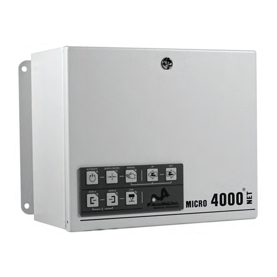
Introduction The MICRO 4000 NET Web Guide Control System is a microprocessor-based control system for medium to large-sized web guides. It is compatible with AccuWeb’s dynamically compensated ultrasonic and infrared edge detectors, digital line guide, remote stations, and all linear actuators. - Page 8 • Auxiliary analog and digital I/O • Input voltage: 90-132 VAC or 180-264 VAC, 50/60 Hz, single-phase 3. MICRO 4000 NET PWM Motor Drive • Fast, accurate response to web movement • Drives brush or brushless DC motors up to 746 watts (1.0 HP) 4.
- Page 9 6. Fieldbus Interface (optional) • Links the MICRO 4000 NET system with a remote PLC or computer through a fieldbus network • Compatible with most fieldbus protocols, including DeviceNet, Profibus, ControlNet, Modbus Plus, Modbus/TCP, and Ethernet TCP/IP • Provides control of operating mode, guide point position, and other functions •...
-
Page 10: Installation
Installation The MICRO 4000 NET system has been tested, calibrated, and run at the factory in a closed-loop configuration. After installation, most systems may be started up and operated without further adjustment. Refer to the connection and wiring diagrams on page 137 for cable installation information. - Page 11 c) Connect the cable to the terminal block located inside the enclosure. d) Make sure the circuit board is free of metallic debris such as screws, lockwashers, and wire strands. e) If any of the cables have been removed, shortened, or modified in any way, make sure the connections agree with the appropriate connection and wiring diagrams located on page 137.
- Page 12 e) Press the EDGE A, EDGE B, or LINE button to select the sensor under test. Press the AUTOMATIC button. g) Slowly move the sensor left or right and observe how the guide reacts. The guide should move the web so that it follows (or chases) the movement of the sensor. Edge detector: The guide should move the web so that the edge of the web is always aligned with the edge detector’s guide point.
-
Page 13: Operation
Operation The MICRO 4000 NET may be configured for a wide variety of applications, but most configurations share the same basic operating procedure: 1) Press the SERVO-CENTER button and wait for the web guide to drive to the center of travel. -
Page 14: Troubleshooting
Troubleshooting The following checklist has been provided to assist in the analysis and repair of potential trouble situations with the MICRO 4000 NET system. If a situation occurs that is not described in this list, contact AccuWeb for assistance. Problem... - Page 15 INHIBIT input polarity is set wrong. Set parameter 19 to the correct value. Refer to page 17 for more information about setting controller parameters. New software was installed during routine maintenance. Non-volatile memory contains invalid data or has malfunctioned. Reset all parameters to their default values: Caution: This procedure will erase all previously entered parameter settings! Be sure to record all current settings on page 39 before performing this step.
- Page 16 Excessive web curl. If web flutter or curl exists, change parameters 6 and 18 to higher values. Refer to page 17 for more information about setting controller parameters. All actuators. End-of-travel mode is incorrect. Set parameter 2 to the correct value. Refer to page 17 for more information about setting controller parameters.
- Page 17 Manual-mode speed setting is incorrect. Change the value of parameter 8. Refer to page 17 for more information about setting controller parameters. ® MICRO 4000 NET Web Guide Control System Artisan Technology Group - Quality Instrumentation ... Guaranteed | (888) 88-SOURCE | www.artisantg.com...
-
Page 18: Appendix 1 / Motor Drive Calibration
Appendix 1 / Motor Drive Calibration Note: The PWM motor drive module is not easily accessible, however user adjustment is typically not necessary and is not recommended. PWM Motor Drive The PWM motor drive converts the system command voltage into a drive voltage for the actuator motor. -
Page 19: Micro 4000 ® Net Controller
® MICRO 4000 NET Controller ® MICRO 4000 NET Controller Artisan Technology Group - Quality Instrumentation ... Guaranteed | (888) 88-SOURCE | www.artisantg.com... -
Page 20: Introduction
Fieldbus Interface card. This card is described on page 102. • Has several analog inputs and outputs that may be used for interfacing to voltage-output sensors, PLCs and other MICRO 4000 NET controllers. A setup procedure for these ports is described on page 50. •... -
Page 21: End-Of-Travel Mode
End-of-Travel Mode No feedback. This mode is used when the system has no motor drive output. Actuators with potentiometer feedback (MT, SF, HL, HF, HT, and UHT). These actuators use a potentiometer to sense actuator position and have adjustable end-of-travel and servo-center limits. Caution: To prevent jamming of the actuator make sure the end-of- travel limits are set correctly. -
Page 22: Maximum Deadband
Maximum Deadband The maximum deadband is a zone around the sensor guide point where the motor drive is turned off. The higher the Maximum Deadband value Range: 0 to 100 is set, the farther the web edge or line must move away from the guide point before the motor drive is turned on. -
Page 23: Input A Type
Input A Type Sensor A is not installed. Sensor A is an ultrasonic or IR edge detector connected to the Edge Detector A input. This is the default setting. Note: Set parameter 55 to select sensor type. Sensor A is a digital line guide connected to the Serial I/O interface. Sensor A is an external analog device connected to Analog Input 1. -
Page 24: Edge Detector A Transmit Level
Edge Detector A Transmit Level 1 6 a a. b b b This parameter displays edge detector A’s transmit levels. Digits aa display the beam number and digits bbb display the transmit level. Use the DATA buttons to select the desired beam. Edge Detector B Transmit Level 1 7 a a. -
Page 25: Edge Detector A Blocked Level
Edge Detector A Blocked Level This parameter determines the blocked signal level for edge detector A and is automatically set by the edge detector calibration procedure. The Range: 0 to 255 default value is 0. This parameter value should not be changed manually. Edge Detector B Blocked Level This parameter determines the blocked signal level for edge detector B and is automatically set by the edge detector calibration procedure. -
Page 26: Power-Up Mode
Password This parameter is used for enabling optional software features. To purchase and install optional features, contact AccuWeb for assistance. Range: 0 to 255 Note: To see which features are enabled, set parameter 29 to 1. The displayed data value indicates which feature is enabled: 0 = none, 1 = oscillation, 2 = web width monitor, 4 = integrator. - Page 27 LED Indicator Mode The front-panel switchpad LEDs and edge detector null indicator LEDs are enabled. In this mode one or both null LEDs may be operational depending on which edge detector is selected by the switchpad, fieldbus, or Discrete Isolated Inputs. If Edge A is selected, then edge detector A’s null LED indicates the position of web edge A and detector B’s null LED is off.
- Page 28 Analog Output 1 The output voltage is 0.0 volts. This is the default setting. The output voltage is proportional to the motor drive command signal. The output voltage range is –10 to +10 volts. The output voltage is proportional to the signal read by Input A, Input B, Input C or the centerline combination of Inputs A and B.
- Page 29 This option is used for controlling a servo-valve. The output voltage reacts to positive web error only. The output voltage range is 0 to +10 volts. This option is used for controlling a servo-valve. The output voltage reacts to negative web error only. The output voltage range is 0 to +10 volts.
- Page 30 Same function as option 11, except the output voltage range is 0 to +10 volts. The output voltage is proportional to the guide point value. The output voltage range is -10 to +10 volts. Same function as option 13, except the output voltage range is 0 to +10 volts.
- Page 31 The range of Analog Input 1 is 0 to +5 volts. The range of Analog Input 1 is 0 to +10 volts. The range of Analog Input 1 is -10 to +10 volts. Analog Input 2 Range (actuator position signal) If parameter 2 is set to 1, then the range of Analog Input 2 is automatically set to 0 to +5 volts.
- Page 32 Edge-Loss and Line-Loss Detection Edge-loss and line-loss detection are disabled. This is the default setting. Edge-loss and line-loss detection are enabled. The actuator will stop and the NO FAULT output will turn off when any active sensor enters the edge-loss or line-loss state. The edge-loss or line-loss state occurs when an edge detector becomes completely blocked or unblocked, or the digital line guide loses the line or edge it is following.
- Page 33 Servo Gain and Speed Limit Source Servo Gain is controlled by parameter 5. Auto-Mode Speed Limit is controlled by parameter 7. This is the default setting. Servo Gain and Auto-Mode Speed Limit are controlled by the optional Fieldbus Interface (page 102). Servo Gain is controlled by Analog Input 1.
- Page 34 Switchpad Type Select this option if the input selection buttons on the front-panel switchpad are labeled EDGE A, CENTERLINE, and EDGE B. The EDGE A button selects Input A. The EDGE B button selects Input B. The CENTERLINE button selects Inputs A and B. This switchpad does not allow the selection of Input C.
- Page 35 Activating the AUXILIARY input will set Offset 1 to the current web position. This is typically done only during job set-up, when the system is in Manual or Servo-Center mode. Note: To reset Offset 1 to its default value, select parameter 60, then press the EXIT key.
- Page 36 Sensor A Type Sensor A is an ultrasonic edge detector. This is the default setting. Sensor A is an IR edge detector. Sensor A is a Hi-Temp ultrasonic edge detector. Sensor B Type Sensor B is an ultrasonic edge detector. This is the default setting. Sensor B is an IR edge detector.
- Page 37 The AUXILIARY output is on when Sensor B is nulled. The AUXILIARY output is on when the system is nulled. This option is used only for configuring the resolver’s AUXILIARY output in resolving-centerline systems. The AUXILIARY output must be connected to the guide’s AUXILIARY input. Centerline Configuration When Centerline mode is selected, the system will calculate Input A + Input B.
- Page 38 Note: This mode is available only if the integrator option is installed. Contact AccuWeb for availability. This mode is used for dampening the response of the slave guide in chaser-slave systems. The chaser sensors are connected to Integrator Input 1 and 2 and the slave sensors are connected to Input A, B, and C.
- Page 39 Analog Input 1 (scaled by parameters 43 and 44). Analog Input 2 (scaled by parameters 45 and 46). Integrator Input 1 Polarity Integrator Input 1 is not inverted. This is the default setting. Integrator Input 1 is inverted. Integrator Input 2 Polarity Integrator Input 2 is not inverted.
- Page 40 Integrator Input Offset The integrator input is not offset. This is the default setting. This option offsets the integrator input using Offset 1. This option offsets the integrator input using Offset 2. INHIBIT and AUXILIARY Input Configuration This parameter swaps the function of the INHIBIT and AUXILIARY inputs. This is useful when your application requires either a non-isolated AUXILIARY input, or an opto-isolated INHIBIT input.
- Page 41 Sensor B Transducer Orientation This parameter reverses the order of the transducer beams in Sensor B. This is the default setting. Beam 1 is located at the end of the transducer closest to the pigtail wiring. Beam 1 is located at the end of the transducer farthest from the pigtail wiring.
-
Page 42: Appendix 1 / Parameter Summary
Appendix 1 / Parameter Summary Parameter Description Range Default Setting Notes see note 1 Software version End-of-travel mode Input A polarity 0, 1 Input B polarity 0, 1 Servo gain 0-255 Maximum deadband 0-100 Auto-mode speed limit 0-120 Manual-mode speed 0-120 In end-of-travel limit 0-255... - Page 43 Sensor A gap Sensor B gap Analog output 1 0-18 Analog output 2 (servo-amplifier) 0-18 Analog offset Analog input 1 range Analog input 2 range (actuator) Analog input 1 scale factor (coarse) 0–25599 Analog input 1 scale factor (fine) 0-25599 Analog input 2 scale factor (coarse) 0–25599 Analog input 2 scale factor (fine)
- Page 44 Contact AccuWeb for availability. These parameters function only if the oscillation option is installed. Contact AccuWeb for availability. Option 2 is available only if the integrator option is installed. Contact AccuWeb for availability. ® MICRO 4000 NET Controller...
-
Page 45: Appendix 2 / Error Codes
Appendix 2 / Error Codes The MICRO 4000 NET contains several internal diagnostic routines that verify correct operation and identify specific problems if they occur. Any problem with the system will turn off the No Fault output and display a flashing ‘99’ error code on the numeric display. -
Page 46: Appendix 3 / Oscillation Function (Optional)
Appendix 3 / Oscillation Function (Optional) This optional software feature allows the user to perform web oscillation electronically, thus replacing the mechanical hardware normally required for this function. Web oscillation is primarily used for processing materials that need oscillation to reduce gauge-band build-up on re-wind rolls. -
Page 47: Oscillation Total Travel
The oscillation function is configured by the following parameters. Refer to page 17 for more information about setting controller parameters. Oscillation Mode The oscillation function is off. This is the default setting. The oscillation function is on. The oscillation function is on and the oscillation speed can be varied from the minimum speed (parameter 53) to the maximum speed (parameter 33) by using the Analog Input 1. -
Page 48: Appendix 4 / Inhibit Input
Appendix 4 / Inhibit Input The INHIBIT input allows the actuator to be turned off (inhibited) by a customer-supplied control signal. There are four customer-selectable INHIBIT operating modes. These modes are controlled by parameter 19. Refer to page 17 for more information about setting controller parameters. The INHIBIT input requires an isolated contact closure. -
Page 49: Appendix 5 / Discrete Isolated Inputs
Appendix 5 / Discrete Isolated Inputs The discrete isolated inputs allow the MICRO 4000 NET system to be remotely controlled by the customer's PLC. There are eight control inputs: SERVO-CENTER, EDGE A, EDGE B, LINE / CENTERLINE, MANUAL, IN, OUT, and AUXILIARY. All inputs are opto-isolated. - Page 50 Discrete Isolated Inputs (DC COMMON is connector J9 terminal 9) AUXILIARY Switchpad Connector Input Input Type Action performed when input is activated J9 terminal Function (Param 51) (Param 52) selects Select Automatic mode (guide the web using position AUTO feedback from sensors selected by the EDGE A, EDGE mode B, or LINE / CENTERLINE inputs).
-
Page 51: Appendix 6 / Discrete Isolated Outputs
Appendix 6 / Discrete Isolated Outputs The discrete isolated outputs allow the MICRO 4000 NET system status to be remotely monitored by a customer's PLC. There are five status outputs: IN LIMIT, OUT LIMIT, SERVO-CENTER LIMIT, AUTO MODE, and NO FAULT. All outputs are opto-isolated. - Page 52 Operation: Discrete Isolated Outputs (DC COMMON is connector J10 terminal 7) Connector Output Description J10 terminal This output is on when the actuator has reached the In limit and is off IN LIMIT during normal operation. This output does not function if a MX-series actuator is installed.
-
Page 53: Appendix 7 / Analog Inputs And Outputs
Appendix 7 / Analog Inputs and Outputs This appendix describes how to configure the MICRO 4000 NET controller’s analog inputs and outputs. The MICRO 4000 NET controller has two analog inputs and two analog outputs: Terminal Terminal Description Number Name... - Page 54 Example # 1: Input a sensor signal from another MICRO 4000 NET controller: In this example controller # 1’s analog input is configured to receive a sensor signal from controller # 2. • Find the model number of controller # 2’s sensor in Table 1 and enter the corresponding parameter values into controller # 1.
- Page 55 Example # 1: [continued] For sensors not listed in Table 1 use the following formula: Analog Input Scale Factor = 100 × W • If the sensor signal is connected to Analog Input 1, then enter the result into parameters 43 and 44. If the sensor signal is connected to Analog Input 2, then enter the result into parameters 45 and 46.
- Page 56 Example # 2: Input a voltage from a third-party sensor: Calculate the Analog Input Scale Factor using the formula below. Analog Input Scale Factor = 100 × F ÷ S • If the sensor is connected to Analog Input 1, then enter the result into parameters 43 and 44.
- Page 57 P = Potentiometer scale factor (volts-per-inch). • If the potentiometer is part of an AccuWeb actuator assembly and is connected to the controller’s +5V REF and SIG GND terminals, then refer to Table 4 for the specific potentiometer scale factor value.
-
Page 58: Pointsource™, Widearray™, And Hi-Temp Edge Detectors
PointSource™, WideArray™, and Hi-Temp Edge Detectors PointSource™, WideArray™, and Hi-Temp Edge Detectors Artisan Technology Group - Quality Instrumentation ... Guaranteed | (888) 88-SOURCE | www.artisantg.com... -
Page 59: Introduction
Introduction The MICRO 4000 NET and MICRO 1000 controllers are compatible with AccuWeb’s entire range of PointSource and WideArray ultrasonic and infrared edge detectors, and the MICRO 4000 NET is also compatible with the Hi-Temp ultrasonic edge detector. Refer to page 57 for a list of standard models. -
Page 60: Setup
0.43 [11] In the table above, x indicates don’t care or not used. The Hi-Temp edge detector is compatible only with the MICRO 4000 NET controller. PointSource™, WideArray™, and Hi-Temp Edge Detectors Artisan Technology Group - Quality Instrumentation ... Guaranteed | (888) 88-SOURCE | www.artisantg.com... -
Page 61: Calibration
Calibration The compensated ultrasonic, infrared (IR), and Hi-Temp edge detectors may be calibrated to guide materials that are between 15% and 100% opaque to the detectors’ sensing beam. During the calibration procedure the microprocessor records the signal level twice: once with the sensing beam unblocked, and then a second time with the sensing beam blocked by the material. -
Page 62: Maintenance
Maintenance Ultrasonic Edge Detectors: The ultrasonic edge detectors require no periodic maintenance. If a loss of unblocked signal level is noticed, cleaning of the transducer faces may be required. Clean the transducer faces with a clean cloth dampened with water or a mild soap solution. DO NOT use harsh solvents as this may damage the transducer. -
Page 63: Accubeam 3 Digital Line Guide Sensor
® AccuBeam 3 Digital Line Guide Sensor AccuBeam 3 Digital Line Guide Sensor Artisan Technology Group - Quality Instrumentation ... Guaranteed | (888) 88-SOURCE | www.artisantg.com... -
Page 64: Introduction
17 for more information about setting controller parameters. The Digital Line Guide is compatible with the following controllers and remote station: MICRO 4000 NET or MICRO 1000 Controllers The Digital Line Guide requires an interface cable to connect to these controllers. Cables are available in standard lengths of 12’... -
Page 65: Installation
Installation The Digital Line Guide can be mounted in a variety of ways. Refer to the application drawings and connection drawings on page 137 for installation information. Note: The Digital Line Guide must be mounted 1.00” [25.4mm] above the web surface, and its sight-point scribe marks must be aligned with the roll center-line as shown in the application drawing. -
Page 66: Operation
Operation This section describes the Digital Line Guide’s front panel keys and display, and outlines a basic operating procedure. Display: • The 2-line LCD display is divided into four fields as shown: PARAMETER VALUE GRAPHIC DISPLAY CONTRAST PARAMETER field: Name of the currently selected parameter. VALUE field: Value of the currently selected parameter. - Page 67 6) Verify that the web pattern is visible in the sensor’s graphic display and that the guide point indicator (a dot) is located under the line or edge you want to track. If the pattern or guide point indicator is not visible, perform the auto-calibration routine described on page 65. 7) Press the AUTOMATIC button.
-
Page 68: Calibration
Calibration Digital Line Guide Calibration Procedure: This procedure automatically finds the optimum values for all line and edge tracking parameters. These parameters can also be examined and manually set as described in the Operation section of this manual (page 63). The parameters are described in more detail in the Parameters section of this manual (page 71). - Page 69 Example # 1 - Tracking a line: 1) Suppose you have a series of dark lines printed on white paper, as shown below. The wide lines are 0.050” [1.3mm] wide, the narrow lines are 0.025” [0.6mm] wide, and the lanes between the lines are 0.100”...
- Page 70 Profile’s memory. For the material used in this example the parameters will be set to the following values: a) Pattern is set to Lt-Dk-Lt (Light-Dark-Light) because the registration line is darker than the surrounding background. b) Scan Direction is set to R-to-L (Right-to-Left) so that the sensor will evaluate objects in its field of view beginning with those on the far right.
- Page 71 Example # 2 - Tracking an edge: 1) Suppose you have a narrow black line and a wide yellow stripe printed on silver metallized film, as shown below: Scan direction (Left-to-Right) Left edge of web Right edge of web Sensor’s field of view 0.625”...
- Page 72 a) Pattern is set to Lt-Dk (Light-Dark) because the metallized area to the left of the edge is lighter than the yellow stripe to the right of it. b) Scan Direction is set to L-to-R (Left-to-Right) so that the sensor will evaluate objects in its field of view beginning with those on the far left.
- Page 73 Min/Max Parameters - Glossary: In order to understand the purpose and function of the Min/Max width parameters, it is necessary to define the various parts of standard Line and Edge patterns: Line Patterns Sensor’s field of view (0.625” [15.9mm] wide) Registration line Left edge of web or edge Right edge of web or edge...
-
Page 74: Parameters
Parameters The AccuBeam 3 Digital Line Guide can track lines and edges printed on many different types of materials. There are twelve tracking parameters that can be adjusted to configure the sensor for a particular pattern and background material. These parameters include: LED Color, LED Angle, Filter, Threshold, Pattern, Scan Direction, Min/Max Left, Min/Max Center, and Min/Max Right. - Page 75 Calibrate C a l i b r a t e This parameter initiates the auto-calibration procedure. This procedure automatically finds the optimum values for all line and edge tracking parameters. Complete instructions for using the auto-calibration procedure may be found on page 65. LED Color (Tracking Parameter) This parameter selects the color of the light source.
- Page 76 Pattern (Tracking Parameter) P a t t e r n L t - D k - L t Light-Dark-Light: This setting will cause the sensor to track a dark line printed on a light background. This is the default value. P a t t e r n D k - L t - D k Dark-Light-Dark: This setting will cause the sensor to track...
- Page 77 Maximum Center (Tracking Parameter) M a x C e n t e r 2 5 5 This parameter specifies the maximum acceptable width of the registration line. This parameter is not used when Range: 0 to 255 half-pixels tracking an edge. The default value is 255. Note: A setting of 255 disables this Min/Max rule.
- Page 78 Backlight B a c k l i g h t This parameter controls the LCD display backlight. The default value is on. B a c k l i g h t O F F Start-Up S t a r t - U p This parameter determines which parameter will be displayed first when the Digital Line Guide is powered-up.
- Page 79 Hidden H i d d e n 2 0 0 0 F This parameter can be configured to hide unused parameters. If a parameter is Hidden it cannot be selected Range: 0 to FFFFF or displayed. The value of this parameter is a bit-field and is displayed in hexadecimal (hex) format.
- Page 80 Bit definitions: Bit number 19 18 17 16 15 14 13 12 11 10 Hex digit fifth fourth third second first Hexadecimal (hex) conversion: Bit-field Hex digit Example: Offset, Backlight, Hidden, Read-Only, and Start-up parameters are hidden Bit settings Hex digits AccuBeam 3 Digital Line Guide Sensor Artisan Technology Group - Quality Instrumentation ...
-
Page 81: Keypad Lock
Keypad Lock The Digital Line Guide’s keypad can be Locked or Unlocked to control access to the parameters. This feature is typically used to prevent accidental or unauthorized changes to stored values and to simplify the menu by hiding unused parameters. When the keypad is Locked, the Hidden and Read-Only parameters are activated. -
Page 82: Troubleshooting
Troubleshooting The following checklist has been provided to assist in the analysis and repair of potential trouble situations with the Digital Line Guide. If a situation occurs that is not described in this list, contact AccuWeb for assistance. Problem Solution The display does not display any characters. -
Page 83: Maintenance
Maintenance For best performance, clean the optical window on the underside of the unit if it becomes dusty or dirty. Use a clean, soft (non-abrasive) cloth dampened with a mild soap solution or a cleaning solution suitable for camera lenses. AccuBeam 3 Digital Line Guide Sensor Artisan Technology Group - Quality Instrumentation ... -
Page 84: Appendix 1 / Parameter Summary
Appendix 1 / Parameter Summary Parameter Range Default Profile 1 Profile 2 Profile 3 Profile 4 Profile 5 Job Profile 1-25 ± 16.300 Offset 0.000 Calibrate Blue LED Color Blue Green Diff LED Angle Refl Diff Side Filter 4, 8, 16 Threshold 1 to 127 Lt-Dk-Lt... -
Page 85: Appendix 2 / Line Guide Test Pattern
Appendix 2 / Line Guide Test Pattern Use this test pattern to verify the proper installation and operation of the Digital Line Guide: Test pattern Web direction Sensor cable location AccuBeam 3 Digital Line Guide Sensor Artisan Technology Group - Quality Instrumentation ... Guaranteed | (888) 88-SOURCE | www.artisantg.com... -
Page 86: Accuweb Linear Actuators
® AccuWeb Linear Actuators ® AccuWeb Linear Actuators Artisan Technology Group - Quality Instrumentation ... Guaranteed | (888) 88-SOURCE | www.artisantg.com... -
Page 87: Introduction
Introduction AccuWeb linear actuators are available with a wide variety of motor technologies, power ratings, stroke lengths, and end-of-travel sensor options: • Motor technologies include brush and brushless DC motors. Power ratings span the range of 20 to 746 watts (1.0 HP). -
Page 88: Maintenance
7) Retract and extend the actuator 20 times to distribute grease along the lead screw. 8) Reinstall the actuator and make sure the actuator shuts off before it reaches a mechanical stop. ® AccuWeb Linear Actuators Artisan Technology Group - Quality Instrumentation ... Guaranteed | (888) 88-SOURCE | www.artisantg.com... - Page 89 15) Press the SERVO-CENTER button and verify that the actuator drives to the correct position and stops. Refer to the previous table for the exposed length of the thrust tube. 16) Reinstall the actuator in the machine. ® AccuWeb Linear Actuators Artisan Technology Group - Quality Instrumentation ... Guaranteed | (888) 88-SOURCE | www.artisantg.com...
- Page 90 5) Retract and extend the actuator 20 times to distribute grease along the lead screw. 6) Reinstall the actuator into the PDG and make sure the actuator shuts off before it reaches a mechanical stop. ® AccuWeb Linear Actuators Artisan Technology Group - Quality Instrumentation ... Guaranteed | (888) 88-SOURCE | www.artisantg.com...
-
Page 91: Remote Station - Guide Point Adjust
Remote Station - Guide Point Adjust Remote Station - Guide Point Adjust Artisan Technology Group - Quality Instrumentation ... Guaranteed | (888) 88-SOURCE | www.artisantg.com... -
Page 92: Introduction
The Guide Point Adjust Remote Station is compatible with the following controllers: MICRO 4000 NET or MICRO 1000 Controllers The Guide Point Adjust Remote Station requires an interface cable to connect to these controllers. Cables are available in standard lengths of 12’ [3.6m], 25’ [7.6m], 50’ [15.2 m], 75’... -
Page 93: Operation
Operation This section describes the operation of the Remote Station front panel keys and display. Display: • The 2-line LCD display is divided into three fields as shown: PARAMETER VALUE POSITION PARAMETER field: Name of the currently selected parameter. VALUE field: Value of the currently selected parameter. POSITION field: Current web position. -
Page 94: Parameters
Parameters This section provides a basic procedure for setting the Remote Station parameters and also describes each parameter in detail. The Operation section of this manual (page 90) describes the operation of the Remote Station front panel keys and display. Job Profile J o b P r o f i l e... - Page 95 Display Units U n i t s E N G L I S H This parameter specifies the units of measurement for all dimensional values. In ENGLISH mode all dimensional values are displayed in inches. In METRIC mode all U n i t s M E T R I C dimensional values are displayed in millimeters.
- Page 96 Hidden H i d d e n This parameter can be configured to hide unused parameters. If a parameter is Hidden it cannot be selected Range: 0 to FFFFF or displayed. The value of this parameter is a bit-field and is displayed in hexadecimal (hex) format.
- Page 97 Bit definitions: Bit number 19 18 17 16 15 14 13 12 11 10 Hex digit fifth fourth third second first Hexadecimal (hex) conversion: Bit-field Hex digit Example: Offset 2, Backlight, Hidden, Read-Only, and Start-up parameters are hidden Bit settings Hex digits Remote Station - Guide Point Adjust Artisan Technology Group - Quality Instrumentation ...
-
Page 98: Keypad Lock
Keypad Lock The Remote Station’s keypad can be Locked or Unlocked to control access to the parameters. This feature is typically used to prevent accidental or unauthorized changes to stored values and to simplify the menu by hiding unused parameters. When the keypad is Locked, the Hidden and Read-Only parameters are activated. -
Page 99: Troubleshooting
Troubleshooting The following checklist has been provided to assist in the analysis and repair of potential trouble situations with the Remote Station. If a situation occurs that is not described in this list, contact AccuWeb for assistance. Problem Solution The display does not display any characters. -
Page 100: Remote Station - Auxiliary
Remote Station - Auxiliary Remote Station – Auxiliary Artisan Technology Group - Quality Instrumentation ... Guaranteed | (888) 88-SOURCE | www.artisantg.com... -
Page 101: Introduction
The Auxiliary Remote Station is compatible with the following controllers, sensor, and remote stations: MICRO 4000 NET or MICRO 1000 Controllers The Auxiliary Remote Station requires an interface cable to connect to these controllers. Cables are available in standard lengths of 12’ [3.6m], 25’ [7.6m], 50’ [15.2 m], 75’... -
Page 102: Operation
Operation The Auxiliary Remote Station duplicates the front-panel display and keypad of the other installed remote station or digital line guide. At power-up, a software identification message is displayed for several seconds: R e m o t e S t a t i o n R M T 0 3 A R x x . -
Page 103: Keypad Lock
Keypad Lock The Remote Station’s keypad can be Locked or Unlocked to control access to the parameters. This feature is typically used to prevent accidental or unauthorized changes to stored values and to simplify the menu by hiding unused parameters. When the keypad is Locked, the Hidden and Read-Only parameters are activated. -
Page 104: Troubleshooting
Troubleshooting The following checklist has been provided to assist in the analysis and repair of potential trouble situations with the Remote Station. If a situation occurs that is not described in this list, contact AccuWeb for assistance. Problem Solution The display does not display any characters. -
Page 105: Fieldbus Interface
Fieldbus Interface Fieldbus Interface Artisan Technology Group - Quality Instrumentation ... Guaranteed | (888) 88-SOURCE | www.artisantg.com... -
Page 106: Introduction
When receiving commands from multiple sources, the MICRO 4000 NET obeys the last command received. The Fieldbus Interface card is compatible only with the MICRO 4000 NET Controller. It is not compatible with the MICRO 1000 Controller. -
Page 107: Programming Information
Programming Information The Fieldbus Interface card allows a PLC host to control the MICRO 4000 NET controller. The controller is configured by parameters described on page 17. Some of these parameters may be written by the host to change the system configuration or mode of operation, and all of the parameters may be read by the host to monitor the system status (Note: This feature is limited in this version of software due to program memory constraints). - Page 108 Output Array data format - overview: Output Array – data sent from host to MICRO 4000 NET Word Byte Function Input C Servo Auto Manual Input A Input B Operating Center Centerline Mode Command Auxiliary Null not used Input Indicator...
- Page 109 Output Array data format – detailed description: Output Array bytes 0 and 1 Operating Mode Command Switchpad Byte Function Value Type Action Performed (Param 51) 0 or 1 No change. Select Automatic mode (guide the web using position Auto feedback from sensors selected by the Input A, B, C, or Centerline command bits).
- Page 110 Output Array bytes 0 and 1 Operating Mode Command - continued Switchpad Byte Function Value Type Action Performed (Param 51) Select Input B. Note: To select Centerline mode, set the Input A and B command bits to 0 and the Centerline command bit to 1. Select Input B.
- Page 111 Output Array bytes 0 and 1 Operating Mode Command - continued Switchpad Byte Function Value Type Action Performed (Param 51) not used none not used none not used none not used none not used none not used none Activate the AUXILIARY input. Auxiliary This option is enabled by setting parameter 52.
- Page 112 Output Array bytes 2 and 3 Guide Point Offset Byte Value Action Performed Low byte Sets the guide point to the position indicated by this 16-bit value. 0-255 [0-FFh] High byte Refer to Table 1 on page 114 for the range of allowed values. 0-255 [0-FFh] Output Array bytes 4 and 5 Servo Gain...
- Page 113 Input Array data format – overview: Input Array – data sent from MICRO 4000 NET to host Word Byte Function Actuator Servo In Limit Out Limit No Fault Status Center Input C Operating Servo Auto Manual Input A Input B...
- Page 114 Input Array data format – detailed description: Input Array byte 0 Actuator Status Function Value Status Indicated The actuator has retracted to the In limit position. In Limit The actuator is not at the In limit position. The actuator has extended to the Out limit position. Out Limit The actuator is not at the Out limit position.
- Page 115 Input Array byte 1 Operating Mode Status Function Value Status Indicated Parameter 51 (Switchpad Mode) is set to 0 or 1: Not defined. Auto Parameter 51 (Switchpad Mode) is set to 2: The unit is in Automatic mode. This mode not selected. The unit is in Servo-Center mode.
- Page 116 Input Array byte 1 Operating Mode Status – continued Function Value Status Indicated Parameter 51 (Switchpad Mode) is set to 0: Centerline mode is selected. Input C Parameter 51 (Switchpad Mode) is set to 1: Input C is selected. Centerline Parameter 51 (Switchpad Mode) is set to 2: Input C is selected and the unit is in Automatic mode.
- Page 117 Table 1: Guide Point Offset and Web Position ranges Guide Point Offset Web Position Sensor Model Range Range Sensor Number inches Value Value inches Value Value Type [mm] decimal decimal [mm] decimal decimal 0.064 16352 16416 0.255 16256 16511 1.5x3U 4043-XX [1.63] [3FE0] [4020]...
- Page 118 • The midpoint value for all sensors is 16384 [4000h]. • The Guide Point Offset columns indicate the minimum and maximum values that can be sent to the controller to move the guide point. The controller automatically limits any value that is outside this range (i.e.
-
Page 119: Troubleshooting
Troubleshooting The following checklist has been provided to assist in the analysis and repair of potential trouble situations with the fieldbus interface. If a situation occurs that is not described in this list, contact AccuWeb for assistance. Problem Solution Host is not communicating with the device (DeviceNet) Check items 1-6 and 10 in the table below. -
Page 120: Appendix 1 / Devicenet Interface
The protocol is implemented on many different products from various manufacturers, from smart sensors to operator interfaces and AccuWeb web guides. The media for the fieldbus is a shielded copper cable composed of one twisted pair and two wires for the external power supply. - Page 121 The module is equipped with four status LEDs mounted at the front of the card and one watchdog LED mounted in the middle of the card, used for debugging purposes. The function of the LEDs is described in the figure and tables below. Of the four status LEDs, two of them indicate network and module status, and the other two are reserved for future use.
- Page 122 Fieldbus Interface Artisan Technology Group - Quality Instrumentation ... Guaranteed | (888) 88-SOURCE | www.artisantg.com...
-
Page 123: Appendix 2 / Profibus Interface
Appendix 2 / Profibus Interface Product Specifications: • Card size (H x W x D): 3.38” [86mm] x 2.13” [54mm] x 0.59” [15mm] • Power requirements: None – provided by network • Operating environment: Maximum ambient temperature 120 deg F [48.9 deg C] Humidity 0-90% non-condensing Mounting holes for stand-offs on... - Page 124 The module is equipped with four status LEDs mounted at the front of the card and one watchdog LED mounted in the middle of the card, used for debugging purposes. The function of the LEDs is described in the figure and tables below. Of the four status LEDs, one indicates network status, two indicate module status, and one is reserved for future use.
- Page 125 Fieldbus Interface Artisan Technology Group - Quality Instrumentation ... Guaranteed | (888) 88-SOURCE | www.artisantg.com...
-
Page 126: Appendix 3 / Controlnet Interface
Appendix 3 / ControlNet Interface Product Specifications: • Card size (H x W x D): 3.38” [86mm] x 2.13” [54mm] x 0.59” [15mm] • Power requirements: None - provided by network • Operating environment: Maximum ambient temperature 120 deg F [48.9 deg C] Humidity 0-90% non-condensing Mounting holes for stand-offs on... - Page 127 The module is equipped with four status LEDs mounted at the front of the card. The function of the LEDs is described in the figure and tables below. Of the four status LEDs, two of them indicate module status, and the other two indicate channel status. Module status Channel A Channel B...
- Page 128 Fieldbus Interface Artisan Technology Group - Quality Instrumentation ... Guaranteed | (888) 88-SOURCE | www.artisantg.com...
-
Page 129: Appendix 4 / Modbus Plus Interface
Appendix 4 / Modbus Plus Interface Product Specifications: • Card size (H x W x D): 3.38” [86mm] x 2.13” [54mm] x 0.59” [15mm] • Power requirements: None – provided by network • Operating environment: Maximum ambient temperature 120 deg F [48.9 deg C] Humidity 0-90% non-condensing Mounting holes for stand-offs on... - Page 130 The module is equipped with four status LEDs mounted at the front of the card and one watchdog LED mounted in the middle of the card, used for debugging purposes. The function of the LEDs is described in the figure and tables below. Of the four status LEDs, three of them indicate network and module status, and one is reserved for future use.
- Page 131 NET) must use register 41025. If the MICRO 4000 NET is located on a Modbus Plus network using a NOM module, do not forget to include the slot number on the NOM module along with the node address of the MICRO 4000 NET unit, in hex format, in the first routing path address.
- Page 132 Fieldbus Interface Artisan Technology Group - Quality Instrumentation ... Guaranteed | (888) 88-SOURCE | www.artisantg.com...
-
Page 133: Appendix 5 / Ethernet Tcp/Ip And Modbus/Tcp Interface
Appendix 5 / Ethernet TCP/IP and Modbus/TCP Interface Product Specifications: • Card size (H x W x D): 3.38” [86mm] x 2.13” [54mm] x 0.59” [15mm] • Power requirements: None – provided by network • Operating environment: Maximum ambient temperature 120 deg F [48.9 deg C] Humidity 0-90% non-condensing... - Page 134 The module is equipped with four status LEDs mounted at the front of the card and one watchdog LED mounted in the middle of the card, used for debugging purposes. The function of the LEDs is described in the figure and tables below. The four status LEDs indicate network and module status.
- Page 135 IP address of the card. After changing the IP address of the card, set the DIP switches to 0 and cycle power to the MICRO 4000 NET. The card’s FLASH memory will now load the new IP address from FLASH memory.
- Page 136 Fieldbus Interface Artisan Technology Group - Quality Instrumentation ... Guaranteed | (888) 88-SOURCE | www.artisantg.com...
-
Page 137: Service / Return Authorization
Please have the system model number and serial number available prior to your call or include it in your correspondence. Field service is available to assist in installation and/or troubleshooting. Contact AccuWeb for price and availability. Important: Before returning equipment to AccuWeb please verify that all mechanical and electronic components are secured for shipping. -
Page 138: Restocking Policy
Restocking Policy The following is our restocking policy: Restocking Charge: The exchange or return of parts and/or equipment will be subject to inspection in seller’s plant. a) All returned parts will include a restocking charge. The only exception will be when the exchange is required because of mistakes by the seller. -
Page 139: Warranty Policy
(1) year from date of delivery. On web guide systems installed by the buyer, AccuWeb, Inc. will replace or repair, at its option, any defective parts returned to AccuWeb, Inc., freight and customs duties prepaid, at no charge to the buyer. -
Page 140: Installation Drawings
1. Application drawing # AC-6554 This drawing shows the enclosure mounting hole pattern. 2. Connection diagram #EB-8544 This drawing shows the connections inside the MICRO 4000 NET enclosure. 3. Connection diagram #EB-9849 This drawing shows how to configure the PWM motor drive’s power supply 4. - Page 141 Artisan Technology Group - Quality Instrumentation ... Guaranteed | (888) 88-SOURCE | www.artisantg.com...
- Page 142 Artisan Technology Group - Quality Instrumentation ... Guaranteed | (888) 88-SOURCE | www.artisantg.com...
- Page 143 Artisan Technology Group - Quality Instrumentation ... Guaranteed | (888) 88-SOURCE | www.artisantg.com...
- Page 144 Artisan Technology Group - Quality Instrumentation ... Guaranteed | (888) 88-SOURCE | www.artisantg.com...
- Page 145 Artisan Technology Group - Quality Instrumentation ... Guaranteed | (888) 88-SOURCE | www.artisantg.com...
- Page 146 Artisan Technology Group - Quality Instrumentation ... Guaranteed | (888) 88-SOURCE | www.artisantg.com...
- Page 147 Artisan Technology Group - Quality Instrumentation ... Guaranteed | (888) 88-SOURCE | www.artisantg.com...
- Page 148 Artisan Technology Group - Quality Instrumentation ... Guaranteed | (888) 88-SOURCE | www.artisantg.com...
- Page 149 Artisan Technology Group - Quality Instrumentation ... Guaranteed | (888) 88-SOURCE | www.artisantg.com...
- Page 150 Artisan Technology Group - Quality Instrumentation ... Guaranteed | (888) 88-SOURCE | www.artisantg.com...
- Page 151 Artisan Technology Group - Quality Instrumentation ... Guaranteed | (888) 88-SOURCE | www.artisantg.com...
- Page 152 Artisan Technology Group - Quality Instrumentation ... Guaranteed | (888) 88-SOURCE | www.artisantg.com...
- Page 153 Artisan Technology Group - Quality Instrumentation ... Guaranteed | (888) 88-SOURCE | www.artisantg.com...
- Page 154 Artisan Technology Group - Quality Instrumentation ... Guaranteed | (888) 88-SOURCE | www.artisantg.com...
- Page 155 Artisan Technology Group is your source for quality new and certified-used/pre-owned equipment SERVICE CENTER REPAIRS WE BUY USED EQUIPMENT • FAST SHIPPING AND DELIVERY Experienced engineers and technicians on staff Sell your excess, underutilized, and idle used equipment at our full-service, in-house repair center We also offer credit for buy-backs and trade-ins •...
Need help?
Do you have a question about the MICRO 4000 NET and is the answer not in the manual?
Questions and answers