Advertisement
Quick Links
Instruction Manual
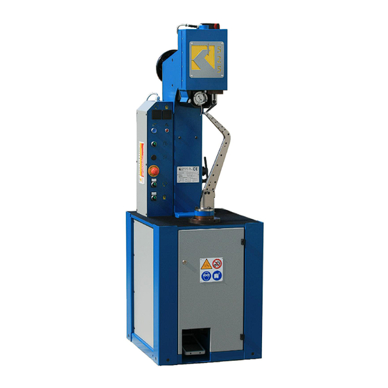
for Electronic Two-Thread Lockstitch Sewing Machine for Soles model F525 N
MODEL
SERIAL N.
YEAR OF CONSTRUCTION : ...............
Manual Revision Number
Builder Company and authorized to supply the Technical Documentation :
FALAN s.r.l.
Via Buscaglia, 14 - 27029 VIGEVANO (ITALIA)
Tel. +39 0381 346373
Fax +39 0381 346375
Codice fiscale/Partita I.V.A. 00293540183
INTERNET: http://www.falan.it
E-mail: info@falan.it
Generated by Foxit PDF Creator © Foxit Software
http://www.foxitsoftware.com For evaluation only.
Footwear Machine Manufacturers
FALAN
( ENGLISH - Translation from Italian Original Language )
: F525 N
: ...............
3
:
Advertisement

Subscribe to Our Youtube Channel
Summary of Contents for FALAN F525 N
- Page 1 For evaluation only. Footwear Machine Manufacturers FALAN ( ENGLISH - Translation from Italian Original Language ) Instruction Manual for Electronic Two-Thread Lockstitch Sewing Machine for Soles model F525 N MODEL : F525 N SERIAL N. : ....YEAR OF CONSTRUCTION : ....
- Page 2 For evaluation only. Footwear Machine Manufacturers FALAN ( ENGLISH - Translation from Italian Original Language ) Instruction Manual for Electronic Two-Thread Lockstitch Sewing Machine for Soles model F525 N MODEL : F525 N SERIAL N. : ....YEAR OF CONSTRUCTION : ....
- Page 3 Generated by Foxit PDF Creator © Foxit Software http://www.foxitsoftware.com For evaluation only. INDEX LIST Important details for manual consultation MACHINE DESCRIPTION Protection and precautions to be taken for safety reasons Residual Risks Emergency signage on the machine Position of the emergency signage on the machine TECHNICAL FEATURES OF THE PROPER USE AND REASONABLY FORESEEABLE Danger and warnings against incorrect use of machine...
- Page 4 Generated by Foxit PDF Creator © Foxit Software http://www.foxitsoftware.com For evaluation only. MACHINE RUNNING OPERATIONS Threading preparation 8.2.1 Horn threading for Blake stitching 8.2.2 Horn thread stripper plug adjustment 8.2.3 Shuttle spool threading order Position of article for stitching MACHINE USE Work cycle description Machine electrical layout plan Machine compressed air pneumatic layout.
- Page 5 Generated by Foxit PDF Creator © Foxit Software http://www.foxitsoftware.com For evaluation only. Important information necessary for manual consultation: 1) In all the technical descriptions , the location of all accessories and various machine parts is always given in relation to the control and work position. This machine has been designed for use by a single operator for safety reasons.
-
Page 6: Machine Description
For evaluation only. MACHINE DESCRIPTION. The Mod. 525N machine manufactured by the FALAN s.r.l. company, is a lock stitch sewing machine with interchnageable horns both for traditional stitching (Blake), and for side stitching (Opanka) of shoe soles. The sewing operation is carried out by a needle and shuttle system, mechanically run by a transmission shaft, cam and gears, controlled by an electronic motor and V-belt. - Page 7 Generated by Foxit PDF Creator © Foxit Software http://www.foxitsoftware.com For evaluation only. Protections and precautions to be taken for safety reasons. The manufacturer has provided for the following safety precautions: - Closeable front door on the sewing head that can be opened with the key supplied with the machine.
- Page 8 Generated by Foxit PDF Creator © Foxit Software http://www.foxitsoftware.com For evaluation only. 1.2 Residual Risks. In the previous paragraphes some situations, potentially classificable as “Residual Risk”, have been identified. The “Residual Risk” is a more or less dangerous situation (for the Operator or for anybody who approaches to the machine) that is not eliminable becouse of the kind of manifacture the machine is used as or becouse of other reasons.
- Page 9 Generated by Foxit PDF Creator © Foxit Software http://www.foxitsoftware.com For evaluation only. 1.3 Emergency signage on the machine Hereunder pls. find the prospectus of the emergency signage on the machine - WRITABLE STIFF DATA PLATE: it contains informations concerning the machine. - CAUTION, DON'T REMOVE THE SAFETY DEVICES.
- Page 10 Generated by Foxit PDF Creator © Foxit Software http://www.foxitsoftware.com For evaluation only. 1.4 Position of the emergency signage on the machine Fastened by a mechanical connection with 2 rivets of 3 mm Fastened by a mechanical connection with 2 rivets of 3 mm front view Fastened by a mechanical connection Fastened by a mechanical...
-
Page 11: Technical Information
Generated by Foxit PDF Creator © Foxit Software http://www.foxitsoftware.com For evaluation only. TECHNICAL DESCRIPTION OF THE MOD. 525N MACHINE. FEATURES TECHNICAL INFORMATION Machine measurements width 550 mm depth 689 mm height 1705 mm Measurements including packing width 820 mm depth 820 mm height 1850 mm... - Page 12 For evaluation only. 3 PROPER USE AND REASONABLY FORESEEABLE The Mod. 525N manufactured by the FALAN S.r.l. company, is an electronic lock stitch with interchangeable horns for Blake or Opanka sole stitching. Any operations other than those for which the machine was designed are considered incorrect use, and can damage the machine, as well as creating a danger hazard for the operator.
- Page 13 Generated by Foxit PDF Creator © Foxit Software http://www.foxitsoftware.com For evaluation only. TRANSPORT AND HANDLING OF THE MACHINE. Passing through the machine head is a cylindrical hole for inserting a raising beam. Use a beam with two end bolts, that can be dismantled for beam insertion into the hole, then bolt very tightly to ensure that the machine does not fall causing danger during transport.
- Page 14 Generated by Foxit PDF Creator © Foxit Software http://www.foxitsoftware.com For evaluation only. Drawing 3 Warning: - Whether the machine is shipped in an open or closed wooden crate, all handling must be carried out appropriately according to the type of packing. .
- Page 15 Generated by Foxit PDF Creator © Foxit Software http://www.foxitsoftware.com For evaluation only. Trasporto macchina in cassa Open or closed wooden crate transport di legno o gabbia Drawing 4 - Take great care to ensure that nobody is present in the hoisting area in order to avoid injuries to personnel during handling of the lifted load.
-
Page 16: Machine Installation
Generated by Foxit PDF Creator © Foxit Software http://www.foxitsoftware.com For evaluation only. MACHINE INSTALLATION. 5.1 Machine measurements. The maximum measurements of the Mod. 525N machine are shown in the drawing below. Drawing N° 5. During machine installation, the pallet fixing brackets are removed, so the width of the machine is reduced from 689 mm to 550 mm. - Page 17 Generated by Foxit PDF Creator © Foxit Software http://www.foxitsoftware.com For evaluation only. 5.2 Mod. 525N Base. For correct functioning, the machine does not need to be bolted to the flooring. Drawing N° 6.
- Page 18 Generated by Foxit PDF Creator © Foxit Software http://www.foxitsoftware.com For evaluation only. 5.3 Front view with the main Mod. 525N machine reference points. Drawing 7. safety switch front head light spot shuttle,needle, foot electrical equipment control panel Horn spool winder block technical information plate safety switch heater...
- Page 19 Generated by Foxit PDF Creator © Foxit Software http://www.foxitsoftware.com For evaluation only. 5.4 Distances to be observed around the machine. For correct use of the machine, and to permit safe and easy repairs and maintenance, it is adviseable to respect the minimum distances shown in the drawing. Drawing 8.
- Page 20 Generated by Foxit PDF Creator © Foxit Software http://www.foxitsoftware.com For evaluation only. SETTING UP AND PREPARATION OF THE MACHINE READY FOR USE. 6.1 Accessory assembly. The machine is completely assembled in the manufacturing plant. 6.2 Preliminary control checks. On reception of the machine, it is adviseable to: - check that all the machine components have arrived at destination.
- Page 21 Generated by Foxit PDF Creator © Foxit Software http://www.foxitsoftware.com For evaluation only. 6.3 Connection to external energy supplies. 6.3.1. Connection to electrical supply. The machine is supplied with the machine cable complete with plug. Therefore the cable only has to be plugged in to the main electricity supply, after having controlled that the voltage and frequency of the motors and electrical components on the machine are the same as those on the main supply line at the user’s factory.
- Page 22 Generated by Foxit PDF Creator © Foxit Software http://www.foxitsoftware.com For evaluation only. 6.3.2 Connection to compressed air supply. Connect the filter-reducer block on the machine with the compressed air supply by sliding the flexible supply tubing into the appropriate click-on attatchment located on the back wall of the machine base, on the top right hand side when seen facing the rear of the machine.
- Page 23 Generated by Foxit PDF Creator © Foxit Software http://www.foxitsoftware.com For evaluation only. 6.4. Checks, adjusting and setting to be carried out. 6.4.1. Correct motor rotation direction check. The Machine has an engine 220V- 50/60 Hz Monophase and does not require verification of the rotation. Drawing 11.
- Page 24 Generated by Foxit PDF Creator © Foxit Software http://www.foxitsoftware.com For evaluation only. 6.4.2. Compressed air adjustment. Set the compressed air supply rate for the machine by using the pressure setting knob located on the filter- reducer block. The established pressure rating is visible on the pressure gauge dial. Warning: Recommended pressure: 5 bar.
- Page 25 Generated by Foxit PDF Creator © Foxit Software http://www.foxitsoftware.com For evaluation only. 6.4.3. Stitch length adjustment. To set the stitch length , proceed as follows. - Turn off the machine at the main switch and disconnect the machine cable from the elctricity supply.
- Page 26 Generated by Foxit PDF Creator © Foxit Software http://www.foxitsoftware.com For evaluation only. 6.4.4. Adjustment of cogged pinion for whirl control. The correct setting of the cogged pinion and whirl ensures longer working life. When the cogs of the two components become worn and are no longer a perfect fit, adjust them closer together. To adjust this setting, proceed as follows: - Turn off the machine with the main switch and disconnect the machine cable from the elctricity supply.
- Page 27 Generated by Foxit PDF Creator © Foxit Software http://www.foxitsoftware.com For evaluation only. 6.4.5. Setting of presser foot support bar height. (art.n.5417.20) To set the height correctly, proceed as follows: - Turn off the machine using the main switch and disconnect the machine cable from the electricity supply.
- Page 28 Generated by Foxit PDF Creator © Foxit Software http://www.foxitsoftware.com For evaluation only. 6.4.7. Setting the needle holder bar (art. n. 5415.20) To set, refer to paragraph 10.8. needle holder bar replacement. 6.4.8. Presser foot pressure adjustment. (art.n.5417.20). To set, proceed as follows: - Turn off the machine with the main switch and disconnect the machine cable from the electricity supply.
- Page 29 Generated by Foxit PDF Creator © Foxit Software http://www.foxitsoftware.com For evaluation only. 6.4.10. Horn thread tension adjustment. To adjust the tension, proceed as follows: - Turn the machine off using the main switch and disconnect the machine cable from the electricity supply.
- Page 30 Generated by Foxit PDF Creator © Foxit Software http://www.foxitsoftware.com For evaluation only. 6.4.11. Setting operation for hidden stitch sewing.. Operating as indicated the machine cuts the sole and at the same time stitches it. This type of working produces neither a channel or a grooving, but simply a cut on the sole, in which the stitching enters and is hidden.
- Page 31 Generated by Foxit PDF Creator © Foxit Software http://www.foxitsoftware.com For evaluation only. 6.4.12. Check on correct function of spring n.5468.04. From time to time, It is adviseable to control that the spring n. 5468.04 presses part n. 5443.00 upwards so that the plug n.
- Page 32 Generated by Foxit PDF Creator © Foxit Software http://www.foxitsoftware.com For evaluation only. SEWING MACHINE SETTING OPERATIONS 7.2 Shuttle position setting. To set the shuttle position, proceed as follows: - Turn off the machine using the main switch and disconnect the machine cable from the electricity supply.
- Page 33 Generated by Foxit PDF Creator © Foxit Software http://www.foxitsoftware.com For evaluation only. 7.3 Thread puller position setting. (lever n. 6214.00, tab. 4) To set the thread puller position, proceed as follows - Turn off the machine using the main switch and disconnect the machine cable from the electricity supply.
- Page 34 Generated by Foxit PDF Creator © Foxit Software http://www.foxitsoftware.com For evaluation only. 8 SETTING UP THE MACHINE READY FOR WORK. The machine is designed with the operating position in front of the machine. Drawing 20 Postazione di lavoro e di comando 8.1.
- Page 35 Generated by Foxit PDF Creator © Foxit Software http://www.foxitsoftware.com For evaluation only. 8.2 Threading preparation. 8.2.1. Horn threading for Blake stitching. To carry out this operation, proceed as follows: - Turn off the machine using the mains switch and disconnect the machine cable from the electricity supply.
- Page 36 Generated by Foxit PDF Creator © Foxit Software http://www.foxitsoftware.com For evaluation only. 8.2.2. Horn thread stripper plug setting. After passing through the emulsion in the container, the thread then passes through a rubber stripper plug with a center hole (n.2305) located in a housing just above the emulsion container. This stripper plug is used to remove the excess emulsion on the thread, leaving only the quantity necessary for correct stitching results.
- Page 37 Generated by Foxit PDF Creator © Foxit Software http://www.foxitsoftware.com For evaluation only. Drawing 21...
-
Page 38: Machine Use
Generated by Foxit PDF Creator © Foxit Software http://www.foxitsoftware.com For evaluation only. 8.3 Position of article to be stitched. The article to be stitched must be placed between the horn tip and the presser foot. 9. MACHINE USE. 9.1. Description of the function —Action —> Consequence Cycle. The functioning sequence of the Mod. - Page 39 Generated by Foxit PDF Creator © Foxit Software http://www.foxitsoftware.com For evaluation only. 6) Once the stitching has been completed: release the control pedal —> the gear will be released and the brake will become engaged —> the mechanical sewing parts will stop —>...
- Page 40 Generated by Foxit PDF Creator © Foxit Software http://www.foxitsoftware.com For evaluation only. REPLACEMENT OPERATIONS. All replacement operations in this instruction manual must be carried out only after: - the machine has been switched off (MAIN SWITCH IN O POSITION) - the machine cable has been disconnected from the electricity supply - the draft tap for the compressed air supply near the filter-reducer block has been closed, and all the compressed air in the pneumatic installation has been emptied.
- Page 41 Generated by Foxit PDF Creator © Foxit Software http://www.foxitsoftware.com For evaluation only. 10.2 Shuttle heater resistor replacement. To replace this resistor, proceed as follows: - Turn off the machine using the MAIN SWITCH and disconnect the machine cable from the electricity supply - Eliminate the blocking effect produced by the sphere and spring wheat M6x15 cod.
- Page 42 Generated by Foxit PDF Creator © Foxit Software http://www.foxitsoftware.com For evaluation only. 10.3 Needle replacement. Proceed as follows: - Turn off the machine using the MAIN SWITCH and disconnect the machine cable from the electricity supply. - Loosen the fixing screw n. 90030.5, just enough to remove the screw easily, - Place in the seat the new needle, pushing it upwards until his setback, - Tighten the screw 90030.5 - Check that the flat side of the needle is facing the operator, in this way the needle will be at an...
- Page 43 Generated by Foxit PDF Creator © Foxit Software http://www.foxitsoftware.com For evaluation only. 10.3.1 Suggested needle size to be used in proportion to thread size. N° of strands Needle size 2 - 2.5 - 3 3 - 3.5 - 4 3.5 - 4 - 4.5 4.5 - 5 - 5.5 Thread diameter in mm Needle N°...
- Page 44 Generated by Foxit PDF Creator © Foxit Software http://www.foxitsoftware.com For evaluation only. 10.4 Loop opener replacement. (art. 0231) Proceed as follows: - Turn the machine off using the MAIN SWITCH, and disconnect the machine cable from the electricity supply. - Loosen the nut n. 90806.5 located on the side of part n. 0211 ( loop opener lever) and remove the part 0231 to be replaced.
- Page 45 Generated by Foxit PDF Creator © Foxit Software http://www.foxitsoftware.com For evaluation only. 10.5 Replacement of loop opener support (art. N. 0211) Proceed as follows: - Turn off the machine using the MAIN SWITCH, and disconnect the machine cable from the electricity supply.
- Page 46 Generated by Foxit PDF Creator © Foxit Software http://www.foxitsoftware.com For evaluation only. 10.6 Whirl replacement. To carry out this operation, proceed as follows: - Turn off the main switch and disconnect the machine cable from the main supply. - By turning the handwheel n.6415.00, bring the graduated cam, n.6406.00 to 0.0 position. - Place the horn curve to the left of the operator.
- Page 47 Generated by Foxit PDF Creator © Foxit Software http://www.foxitsoftware.com For evaluation only. 10.8 Replacement of the needle holder bar Proceed as follows: . turn off the main switch and disconnect the machine cable from the main supply. . unloose the 2 screws placed on the clamp n.7418.00, .
- Page 48 Generated by Foxit PDF Creator © Foxit Software http://www.foxitsoftware.com For evaluation only. 10.9 Replacement flexible cord Do as followed : · switch off the machine with the general switcher and take off the electrical plug, · extract the tip n. 5504.00 unscrewing the two grub screws n. 90503.5, ·...
- Page 49 Generated by Foxit PDF Creator © Foxit Software http://www.foxitsoftware.com For evaluation only. ACCESSORIES 11.1 Heater. The heater system must be filled with shoemaker’s wax or parafin. The wax or parafin is melted by the electrical heating resistor. The temperature of the heater is set using the thermostat TEMPERATURE RESISTOR SETTING and the choice of the voltage (20 or 24 volts) is obtained using the three way switch HEATER RESISTOR SWITCH.
- Page 50 Generated by Foxit PDF Creator © Foxit Software http://www.foxitsoftware.com For evaluation only. 11.1.1. Spool stripper plug adjustment. After wax or parafin soaking, on leaving the heater, the thread then passes through a rubber stripper plug n. 0061 set in a housing in the heater cover. This stripper plug is used to remove excess wax or parafin from the thread, leaving only the quantity necessary for good stitching results.
- Page 51 Generated by Foxit PDF Creator © Foxit Software http://www.foxitsoftware.com For evaluation only. EQUIPPED WITH OPANKA HORN AND BLAKE HORN. 12.1 Assembly of horn for Opanka stitching. The Opanka horn is used for side stitching the shoe sole. To replace the horn, proceed as follows: - Switch off the mains switch and disconnect the machine from the main supply line.
- Page 52 Generated by Foxit PDF Creator © Foxit Software http://www.foxitsoftware.com For evaluation only. Drawing 30 Opanka horn with thread path...
- Page 53 Generated by Foxit PDF Creator © Foxit Software http://www.foxitsoftware.com For evaluation only. 12.2 Assembly of horn BLAKE The BLAKE horn is used for shoe bottom stitching. To replace this horn, proceed as follows: - Turn off the main switch and disconnect the machine from the main supply line. - Unscrew the 3 screws n.
-
Page 54: Repairs And Maintenance
Generated by Foxit PDF Creator © Foxit Software http://www.foxitsoftware.com For evaluation only. REPAIRS AND MAINTENANCE 13.1 Maintenance Correct maintenance ensures longer working life of the machine, better running conditions, good sewing results, and is a guarantee for the safety measures provided by the manufacturer. 13.2 Regular maintenance operations. - Page 55 Generated by Foxit PDF Creator © Foxit Software http://www.foxitsoftware.com For evaluation only. 13.3 Advice concerning lubrification. The machine should be lubrified every day at the beginning of each work shift. Particular care should be taken with all rotating and sliding parts . The choice of oil is very important, since it must be neither too fluid nor too dense.
- Page 56 Generated by Foxit PDF Creator © Foxit Software http://www.foxitsoftware.com For evaluation only. 13.4 Operations which must be carried out by manufacturer’s qualified personnel. Below is a list of all the operations which require technical competence and which must be carried out by the manufacturer’s qualified personnel: The user must under no condition : - replace any seals orgaskets...
- Page 57 Generated by Foxit PDF Creator © Foxit Software http://www.foxitsoftware.com For evaluation only. Problem: The loop opener picks up both threads Reason and solution: Loop opener not in correct position. Problem: The horn turns only when the machine is running. Reasons and solutions: - The pinion and whirl have damaged cogs, or are not set correctly.
- Page 58 Generated by Foxit PDF Creator © Foxit Software http://www.foxitsoftware.com For evaluation only. 13.6 Spare parts and parts subject to wear and tear. Below are listed all the spare parts for replacement which are subject to wear and tear, plus the quantities to be kept in stock for a working period of one year.
- Page 59 Generated by Foxit PDF Creator © Foxit Software http://www.foxitsoftware.com For evaluation only. 13.7 Equipment supplied with the machine Model 525 Item Description Quantity Guide spacer 5418.10 Thread picker for the horn 5107.04 Spool/bobbin 0478 Loop spreader 0231 Small stud 0229 Nut M6 for the small stud 90806.5 Spool extractor...
- Page 60 Generated by Foxit PDF Creator © Foxit Software http://www.foxitsoftware.com For evaluation only. DEMOLITION INSTRUCTIONS FOR THE MOD. 525 MACHINE Whenever, and for whatever reason the machine is to be eliminated and demolished, certain basic rules must be observed to safeguard public health and the environment in which we live: - Eliminate even the smallest traces of oil and grease on the machine;...
-
Page 61: Main Warnings
Generated by Foxit PDF Creator © Foxit Software http://www.foxitsoftware.com For evaluation only. MAIN WARNINGS. All operations described in this instruction manual must be carried out with the motor switched off and the machine cable disconnected from the elctricity supply. All setting and maintenance operations must be carried out by qualified expert personnel to elimi nate any danger of injury of damage to the machine. - Page 62 Generated by Foxit PDF Creator © Foxit Software http://www.foxitsoftware.com For evaluation only. For best working conditions, the emulsion container should be filled with a solution of 80% water and 20% emulsionable chemical oil. A can of this oil is supplied with the machine. Before each production cycle, check the level of emulsion in the container, which should always be almost full, and when necessary, top up the solution.
Need help?
Do you have a question about the F525 N and is the answer not in the manual?
Questions and answers