Table of Contents
Advertisement
Advertisement
Table of Contents

Related Manuals for Sicunet Neptune Series

Summary of Contents for Sicunet Neptune Series
- Page 1 Neptune Series Access Control Systems Installation Instructions for 1 Door Systems and 2 & 4 Door Systems with Integrated Power Supplies Document Number: 100100 REV A Installation Instructions for 1 Door and 2 & 4 Door Systems with Integrated Power Supply...
-
Page 2: Table Of Contents
Table of Contents Notifications..............................4 Copyright..............................4 Approvals..............................4 Notice.................................4 Introduction..............................5 Access Control Overview..........................5 System Overview............................5 2 & 4 Door Systems Specifications........................6 Installation of 2 & 4 Door Systems........................7 Installation Check List..........................7 Locating the Controller for Installation.....................7 Mounting the Metal Enclosure – 2 & 4 Door Systems..................8 Tamper Detection............................9 System Power............................9 Power Fault Detection..........................9... - Page 3 Output Wiring Requirements........................33 Powering On and Connecting to a Network....................35 Preparing for the Network........................35 Connecting to the Local Network......................36 Adding Clients to Systems........................37 IP Installer..............................38 System Configuration and Programming....................39 Trouble Shooting............................40 Testing, Maintenance and Service........................42 Parts List...............................42 Contact & Warranty Information........................43 Installation Instructions for 1 Door and 2 &...
-
Page 4: Notifications
Copyright Copyright © 2019, all rights reserved. No part of this document may be reproduced, copied, adapted or transmitted in any form without written permission from Sicunet, Inc. Approvals This equipment has been tested and found to comply with the limits for a Class A digital device, pursuant to part 15 of the FCC Rules. -
Page 5: Introduction
Introduction Access Control Overview Access Control is the selective restriction to a place or resource such as a property, building or room to authorized persons and is a matter of who, where, and when. An access control system is used to automate access control using credentials, credential readers, electric door locks and other devices. -
Page 6: 2 & 4 Door Systems Specifications
2 & 4 Door Systems Specifications General Specifications Processor Quad Core Cortex, 1.5 GHz Memory 1GB DDR3 & 8 GB eMMc Operating System Embedded Linux Transactions > 45 per Second System Power Requirements 115VAC @ 1.5A Operating Temperature 50ºF to 95ºF (10ºC to 35ºC) Enclosure Size (W x H x D) 14.25 x 14.25 x 3.75 in ( 362 x 362 x 95 mm) 2 Door Systems... -
Page 7: Installation Of 2 & 4 Door Systems
Installation of 2 & 4 Door Systems Installation Check List The list below provides a logical sequence for installing a system. This list cannot cover all possible situations and conditions that occur during installation and use and it must be understood that common sense and caution must be exercised by the person(s) installing, maintaining and operating the equipment. -
Page 8: Mounting The Metal Enclosure - 2 & 4 Door Systems
Mounting the Metal Enclosure – 2 & 4 Door Systems The metal enclosure should be mounted vertically on a wall in a secure location. The temperature in the mounting location must be within the system's specified limits. A minimum of 8 inches of space around all sides of the enclosure is recommended. -
Page 9: Tamper Detection
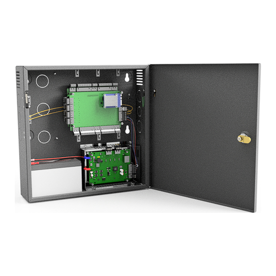
MOUNTING MOUNTING HOLE HOLE TAMPER SWITCH 2 or 4 DOOR CONTROLLER MOUNTING HOLE MOUNTING HOLE GROUNDING POST FOR READER SHIELDS POWER CORD CONNECTOR 12V BATTERY (NOT INCLUDED) *POWER MODULE 2 & 4 Door System Features and Mounting Locations (*There are two types of power modules, one with lock power and one without) Tamper Detection A tamper switch is mounted in the enclosure and is prewired to the controller. -
Page 10: Fire Release Input
Fire Release Input On models that include power for the door locks, the power module is prewired with a normally closed Fire Release input. If the input is opened, power will be disconnected from the connected door locks. This can be used to unlock fail safe door locks. Note: The power module and/or access control system is not listed as and can not be used as a fire warning system. -
Page 11: Input Power Connector
*OUTPUTS 1 & 2 CONNECTOR *OUTPUTS 3 & 4 CONNECTOR POSITIVE BATTERY CONNECTION RED WIRE *FIRE CUTOFF LED INDICATOR RED WHEN ACTIVATED NEGATIVE BATTERY CONTROLLER CONNECTION CONNECTOR BLACK WIRE INPUT POWER CONNECTOR MAIN POWER LED INDICATOR GREEN WHEN PRESENT Power Module Features and Connections (*only included on models with lock power) Input Power Connector Terminal Description... -
Page 12: Output Power Connectors
Output Power Connectors Terminal Description +12 or +24 VDC Output, 375 mA MAX Ground +12 or +24 VDC Output, 375 mA MAX NOTE: This connector is only included on models with lock power. On models that include power for door locks, the output voltage can be individually set for each of the four outputs. -
Page 13: Power Connection
On models that include power for door locks, use the output voltage selection jumpers as shown below to set the voltage to the desired value. Note: Make sure to check specifications of the door lock before applying power. Using the wrong voltage can damage the door lock or power module and void warranties. -
Page 14: Controller Features - 2 & 4 Door Systems
Controller Features – 2 & 4 Door Systems The following shows the controller's features and wiring components. Controller Hardware Identification *DOOR 4 *AUX 3 IN *DOOR 3 DC & REX *AUX 4 IN DC & REX *READER 4 *READER 3 SD CARD OUTPUTS BOTTOM ROW... -
Page 15: Controller Connectors
Input Circuit Configurations The table below shows the different input configurations. These types can be independently configured for each input by the user. Supervised Unsupervised Normally Open Normally Open Note: Use 1K Ohm Resistor Normally Closed Normally Closed Controller Connectors The controller is provided with plugin terminal blocks that are color coded and marked to indicate the proper connection for field wiring. -
Page 16: Request To Exit And Door Position Connectors
Request to Exit and Door Position Connectors Terminal Description Request to Exit Input, Normally Open, Normally Closed or Monitored Ground, Common Connection for REX and DC Inputs Door Position Input, Normally Open, Normally Closed or Monitored. NOTE: REX and DC input types are user configurable options. Request to Exit (REX) Inputs A REX input activated the door output to unlock a door. -
Page 17: Power, Power Fault And Tamper Connector
Auxiliary Inputs Auxiliary inputs are used for general purposes and can be connected to devices such as alarms, detectors and devices that have a switched output. These inputs can be set to normally open (NO), normally closed (NC) or monitored using either a series or parallel resistor and these features may be modified in Device Settings for Aux Inputs. - Page 18 Tamper Input Wiring 1. Disconnect power from the controller. 2. Determine if device you are connecting to the Tamper input is normally open or normally closed (refer to the instructions provided by the device manufacturer). 3. Connect the device to the Tamper input as shown. 4.
- Page 19 Power Wiring 1. Connect the power supply to the 12V and Ground terminals on the connector. 2. Power should only be applied to the system when all connections are secured and tested, and when instructed to apply power. In and Out Reader Connectors Terminal Description +12 VDC Power for the Readers LED Control for the In and Out Readers...
-
Page 20: Controller Outputs
Reader Wiring 1. Disconnect power from the controller. 2. Connect the color coded wires from the reader to the appropriate terminals on the reader connector as shown. Refer to manufacture's instructions for exact color codes for each connection. 3. Remove excess shield from the reader cable to prevent interference with the controller's electronics or other electrical circuits. -
Page 21: Output Wiring Requirements
Output Wiring Requirements The wire used must be of the proper gauge for the load current and distance from the controller to the load. Wires must not be routed in parallel with or in the same conduit with any high voltage AC wiring and all wiring shall conform with the National Electrical Code, NPFA70 and local building codes. - Page 22 Fail Safe DC Door Strike Without power, the door strike is unlocked. Fail Secure AC Door Strike Without power, the door strike is locked. Installation Instructions for 1 Door and 2 & 4 Door Systems with Integrated Power Supply Page...
-
Page 23: Adding 2 Door Expansion
Adding 2 Door Expansion Controllers with only 2 doors can be expanded to 4 doors by adding an optional 2 door expansion module. The module plugs into the back of the 2 door controller and provides the additional inputs and outputs. The 2 Door Expansion Module in installed as follows. 1. -
Page 24: Door System Specifications
1 Door System Specifications General Specifications Processor Quad Core Cortex, 1.5 GHz Memory 1GB DDR3 & 8 GB eMMc Operating System Embedded Linux Transactions > 45 per Second Power Requirements (excluding door locks) Regulated 12VDC @ 2A, Class 2 (not supplied) Operating Temperature 50ºF to 95ºF (10ºC to 35ºC) Enclosure Size (W x H x D) -
Page 25: Installation Of 1 Door Systems
Installation of 1 Door Systems Installation Check List The list below provides a logical sequence for installing a system. This list cannot cover all possible situations and conditions that occur during installation and use and it must be understood that common sense and caution must be exercised by the person(s) installing, maintaining and operating the equipment. -
Page 26: Mounting The 1 Door System
Mounting the 1 Door System The 1 door controller can be mounted vertically or horizontally in an enclosure that is located in a secure location. The aluminum heat sink should face away from the mounting surface. The temperature in the mounting location must be within the system's specified limits. When running wires through knockouts in enclosures, install bushings or conduit connectors as needed to protect wires from damage. -
Page 27: Controller Features 1 Door Systems
Controller Features 1 Door Systems The following shows the controller's features and wiring components. Controller Hardware Identification POWER HEAT SINK HARNESS CONNECTOR *SD CARD *HARDWARE RESET *IP RESET *FACTORY DEFAULT READER HARNESS ETHERNET *controller shown CONNECTOR with cover removed 1 DOOR CONTROLLER LAYOUT Controller Inputs Controllers can monitor door position, request to exit and auxiliary (general purpose) inputs. -
Page 28: Controller Wiring Harnesses
Controller Wiring Harnesses The controller is provided with two plug-in wiring harnesses for connecting field wiring. The harnesses are color coded and marked with labels to indicate the proper connection for field wiring. The Minimum Cable Specifications for the wiring of inputs is 22 AWG Belden or equivalent with a maximum distance of 2000 feet (610 meters). - Page 29 Request to Exit (REX) Input A REX input activated the door output to unlock a door. A REX device can be a press to exit button, motion detector or other device mounted on the secured side of an entrance. REX features may be modified in Device Settings for Doors and can be set to normally open (NO), normally closed (NC) or monitored using either a series or parallel resistor.
- Page 30 Auxiliary Input Wiring 1. Disconnect power from the controller. 2. Determine if device you are connecting to the Auxiliary input is normally open or normally closed (refer to the instructions provided by the device manufacturer). 3. Connect the device to the Auxiliary wires as shown. 4.
- Page 31 Power Fault Input Wiring 1. Disconnect power from the controller. 2. Determine if device you are connecting to the Power Fault input is normally open or normally closed (refer to the instructions provided by the device manufacturer). 3. Connect the device to the Power Fault wires as shown. 4.
-
Page 32: Controller Outputs & Power Input
Reader Wiring 1. Disconnect power from the controller. 2. Connect the color coded wires from the reader to the appropriate wires on the reader 14 pin harness as shown. Refer to manufacture's instructions for exact color codes for each connection. 3. -
Page 33: Output Wiring Requirements
Output Wiring Requirements The wire used must be of the proper gauge for the load current and distance from the controller to the load. Wires must not be routed in parallel with or in the same conduit with any high voltage AC wiring and all wiring shall conform with the National Electrical Code, NPFA70 and local building codes. - Page 34 Door Lock Wiring Door outputs can be configured to operate in a fail safe or fail secure mode. Connect the door locking device to the door output connector as shown below. Refer to the manufacture's specifications to determine the correct operating voltage, current and configuration. Use a power supply dedicated for door lock use.
-
Page 35: Powering On And Connecting To A Network
Powering On and Connecting to a Network Controllers must be located in a secure area and connected to a network that is protected by a security system (firewall, etc.). Before connecting the controller to the network, obtain the following information from you network administrator. Note: a Static IP address should be used when a controller is configured as a server controller. -
Page 36: Connecting To The Local Network
Wizard Starting Page 7. The network configurations may be also accessed through the Sitemap by first clicking the icon at the bottom of the page, then clicking IP Address under Network Settings. Accessing the Site Map 8. After entering the network information, click Save & Reboot and the controller will reboot. Typically rebooting will take less than 2 minutes. -
Page 37: Adding Clients To Systems
is 98.5 feet (30 meters). NOTE: LAN connection is only required for monitoring, reporting and configuration. Once the system is configured, it will operate without a LAN connection. Adding Clients to Systems Some systems have the ability to add additional controllers to increase the number of doors, inputs or outputs or control elevators. -
Page 38: Ip Installer
Linking the Client to the Server 1. Login to the system's server. 2. After logging in, browse to the Site Management and select Client Management. 3. The client will appear in the client management list. Click on the button to connect the client to the server. -
Page 39: System Configuration And Programming
System Configuration and Programming The controller is programmed and managed using a web browser on any computer connected to the local area network. The controller's basic settings can be programmed using the Wizard tool. The Wizard tool helps ensure the that required settings are configured for normal operation. -
Page 40: Trouble Shooting
Trouble Shooting Question Solution – Check the AC outlet's voltage used to power the controller. – For systems using a Fire Cutout, check the status of the fire cutout input to see the power has been deactivated. – Check wiring from the power supply to the controller. –... - Page 41 Trouble Shooting Question Solution – The controller's MAC address is required to obtain a license key. This is printed on How to obtain a license the controller or can be found on the license page after logging in to the UI. key for an unlicensed controller? –...
-
Page 42: Testing, Maintenance And Service
Testing, Maintenance and Service A monthly test of the system and all the components is recommended. ✔ Check that all used inputs and outputs are correctly working with the connected devices. ✔ Check that the system and log backups are occurring at the scheduled times. ✔... -
Page 43: Contact & Warranty Information
Contact & Warranty Information Corporate Office Sicunet, Inc. 4840 Irvine Blvd, #113 Irvine, CA USA 92620 Phone: 857.346.0130 FAX: 714.512.6816 email: info@sicunet.com email: sales@sicunet.com For further assistance, visit the following online resources: www.sicunet.com www.lod.sicunet.com www.faq.sicunet.com Technical Support Contact Information: Hours: M ~ F, 7 AM ~ 3 PM, Pacific Phone: 857.346.0130...
Need help?
Do you have a question about the Neptune Series and is the answer not in the manual?
Questions and answers