Table of Contents
Advertisement
Quick Links
Advertisement
Table of Contents

Related Manuals for Baur Sys compact 2000 M pro

Summary of Contents for Baur Sys compact 2000 M pro
- Page 1 Us er manual Cable fault location system S ys c ompac t 2000 M pro B A U R G m b H ▪ R a i f f e i s e n s t r . ▪ 6 8 3 2 S u l z , A u s t r i a T + 4 3 5 5 2 2 4 9 4 1 - 0 ▪...
- Page 2 BAUR GmbH, 6832 Sulz, Austria. We reserve the right in the interests of our customers to make amendments as a result of further technical development.
-
Page 3: Table Of Contents
Syscompact 2000 M pro Table of contents Table of contents About this manual ..................7 Using this manual ................7 Validity of this user manual ..............7 Applicable documents ................7 Structure of safety instructions ............7 View Settings ..................8 Note on the screenshots and graphics used ........ - Page 4 Table of contents Syscompact 2000 M pro Transportation ................... 31 Packaging ..................31 Ensure the following when transporting ..........31 Transporting the system manually ............. 31 Transporting the system in vehicles ..........32 Shipping the system ................32 Commissioning ..................33 Checks to perform before commissioning .........
- Page 5 Syscompact 2000 M pro Table of contents Printing measurement data ..............45 Configuring and operating the system ............ 46 10.1 Selecting the language ..............46 10.2 Setting the date .................. 46 10.3 Setting the time .................. 47 10.4 Setting the contrast of the display ............47 10.5 Setting the brightness of the indicator lights ........
- Page 6 Table of contents Syscompact 2000 M pro 13.3 Performing acoustic pin-pointing ............73 13.3.1 Safety instructions for the system’s surge mode ....73 13.3.2 Prerequisites ................ 73 13.3.3 Procedure ................74 Putting the testing system out of operation ........... 75 14.1 Safety instructions for decommissioning ...........
-
Page 7: About This Manual
Consider this user manual to be a part of the product and store it in an easily accessible location. If this user manual is lost, please contact BAUR GmbH or your nearest BAUR representative (http://www.baur.eu/baur-worldwide). Validity of this user manual This user manual applies for The Syscompact 2000 M pro cable fault location system from card version A 1.06... -
Page 8: View Settings
About this manual Syscompact 2000 M pro Danger levels Signal words in the safety instructions specify the danger levels. DANGER Will lead to severe injuries or death. WARNING May lead to severe injuries or death. CAUTION May lead to light to moderate injuries. NOTICE May lead to material damage. -
Page 9: Note On The Screenshots And Graphics Used
Syscompact 2000 M pro About this manual Note on the screenshots and graphics used The screenshots and graphics used are intended to illustrate the procedure and may differ slightly from the actual state. 822-175-2 9 / 98... -
Page 10: For Your Safety
Syscompact 2000 M pro OR YOUR SAFETY All BAUR devices and systems are reliable and are manufactured as per state-of-the-art technology. The individual parts and the finished devices are subject to continuous testing by our qualified personnel as part of our quality assurance system. Each device is fully tested before delivery. -
Page 11: Avoiding Dangers, Taking Safety Measures
Comply with the inspection and maintenance conditions. Use only accessories and original spare parts recommended by BAUR. The use of spare parts, accessories and special facilities that are not tested and approved by BAUR could adversely affect the safety, function and characteristics of the product. -
Page 12: Checking And Maintaining The Safety Devices
For your safety Syscompact 2000 M pro 2.3.3 Checking and maintaining the safety devices The safety devices must be inspected regularly for proper condition and function. The Syscompact 2000 M pro must not be operated in the case of defects or non-functional safety devices. - Page 13 Syscompact 2000 M pro For your safety DANGER High electric voltage Danger to life or risk of injury due to electric shock. Before commencing work, the operator must assess the risks for the specific working conditions. Protective measures are based on the risk assessment and must be followed within the workplace.
-
Page 14: Danger During The System's Surge Mode
For your safety Syscompact 2000 M pro 2.3.7 Danger during the system’s surge mode WARNING Potential differences between the system and the earth Danger to life or risk of injury due to electric shock. Potential differences between the system and the earth are possible during surge mode when the system is positioned on the cable route. -
Page 15: Maximum Permissible Output Current In Dc Voltage Mode
Syscompact 2000 M pro For your safety 2.3.8 Maximum permissible output current in DC voltage mode NOTICE The device may be damaged by an excessive output current An excessive output current during DC voltage mode can generate high thermal loads. This will damage the transformer. ... -
Page 16: Dangers From Road Traffic
For your safety Syscompact 2000 M pro When connecting the device to the test object, during the preparation and while performing the measurement, the user can come close to live parts. In so doing, there is danger of touching the active parts directly or indirectly. DANGER Working in the vicinity of adjacent live parts Danger to life or risk of injury due to electric shock. -
Page 17: Special Personal Protective Equipment
Special personal protective equipment Personal protective equipment based on the risk assessment for the relevant working conditions is part of the safety concept of BAUR systems. Observe the internal operating instructions and the safety instructions applicable in your country. -
Page 18: Product Information
Product information Syscompact 2000 M pro RODUCT INFORM ATION Overview of the available cable fault location methods With Syscompact 2000 M pro, you can use any of the following fault location methods: Cable testing with DC voltage Time Domain Reflectometry (TDR) ... -
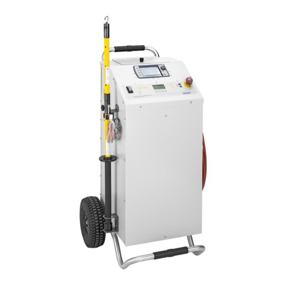
Page 19: Full Illustration Of Syscompact 2000 M Pro
Syscompact 2000 M pro Product information Full illustration of Syscompact 2000 M pro Element Function Cable compartment Provides access to the ports of the IRG 2000 time domain reflectometer IRG 2000 time Is used to perform and evaluate the cable fault pre-location domain reflectometer Further information: Chapter IRG 2000 time domain reflectometer (on page 21) System control panel Is used to switch the system on and off and control the surge voltage generator... -
Page 20: System Control Panel
Product information Syscompact 2000 M pro 3.2.1 System control panel Element Function On/Off switch Is used to switch on and off the system’s power supply Status LEDs Displays the operational earth monitoring status: Green: The operational earthing is connected correctly. The resistance ... -
Page 21: Irg 2000 Time Domain Reflectometer
Syscompact 2000 M pro Product information Element Function Emergency off In the event of an emergency, moves the system to the safe Ready for operation button operating state The emergency off button is equipped with key and lock for protection against unauthorised or unintentional operation. - Page 22 Product information Syscompact 2000 M pro Element Function COMPARE key Calls up the view for comparing the traces It is only possible to compare the traces of the TDR and SIM/MIM measurements. The following buttons are displayed: Insert REF Inserts the reference curve in the FUNCTION view into the actual reflection image DIFF / SPLIT Displays or hides a difference curve for the actual trace and...
- Page 23 Syscompact 2000 M pro Product information Element Function CURSOR key Calls up the view for positioning cursors Further information: Chapter Evaluating reflection images with cursors (on page The following buttons are displayed: Cursor # 0 Is used to display and position the zero cursor Cursor # 1 Is used to display and position a cursor Cursor # 2...
- Page 24 Product information Syscompact 2000 M pro Element Function User interface Is used to display and evaluate the traces Further information: Chapter IRG 2000 user interface (on page 24) IRG 2000 user interface Element Function Zoom Shows whether the view of the reflection image has been enlarged Red outline Shows which trace is currently being displayed: LINE: Trace of the last measurement...
-
Page 25: Safety Devices
Syscompact 2000 M pro Product information Safety devices Operational earth monitoring The operational earthing monitoring checks whether the operational earthing is connected to the station earth (protective earth) on a point with low transition resistance (resistance < 4 ohm). If this test fails, it is not possible to release the high voltage (Ready to switch on operating state). - Page 26 Product information Syscompact 2000 M pro To move the system to the Ready for operation operating state, press the On/Off switch on the system control panel. The system’s green indicator light comes on. The status LED of the operational earth monitoring and the surge protective device ...
-
Page 27: Markings On The System
Indicates that there is a potential risk of danger when using the product and hence the user manual must be observed CE mark Indicates that the device or system conforms to CE. BAUR GmbH Name and address of the manufacturer 6832 Sulz / Austria 822-175-2... -
Page 28: Rating Plate On The Irg 2000 Time Domain Reflectometer
Indicates that there is a potential risk of danger when using the product and hence the user manual must be observed CE mark Indicates that the device or system conforms to CE. BAUR GmbH Name and address of the manufacturer 6832 Sulz / Austria Made in Austria Indicates the country in which the device was manufactured. -
Page 29: Technical Data
Syscompact 2000 M pro Technical data ECHNICAL DATA IRG 2000 Pulse voltage 10 – 60 V Pulse width 40 ns – 10 µs Voltage-proof up to 400 V, 50/60 Hz Output impedance 10 – 250 Ohm Input signal gain 0 – 60 dB Measurement range 0 –... - Page 30 Technical data Syscompact 2000 M pro Surge voltage generator Surge voltage ranges 0 – 8 kV, 0 – 16 kV Surge energy 1024 J Surge sequence 1 – 20 pulses/min, single surge DC voltage 0 – 16 kV Max. permissible output current in Depends on the output voltage DC voltage mode Further information: Chapter Maximum permissible output current in DC...
-
Page 31: Transportation
Syscompact 2000 M pro Transportation RANSPORTATION Packaging 1. Keep the original packaging because it provides the best protection for the system during transportation. 2. If you would like to dispose of the packaging, ensure you comply with the applicable national regulations when doing so. Ensure the following when transporting NOTICE Damage to the device caused by improper transportation and incorrect storage... -
Page 32: Transporting The System In Vehicles
Transportation Syscompact 2000 M pro Ensure that the system always remains in an upright position during transportation. To transport the system manually, tilt the transport trolley into the transport position and pull it along by the transport handle. ... -
Page 33: Commissioning
Syscompact 2000 M pro Commissioning OMMISSIONING Follow the information below: The safety instructions in the chapter For your safety (on page 10) Local safety and accident prevention regulations Safety instructions and regulations according to the state-of-the-art National and international standards and guidelines in the latest applicable version: ... -
Page 34: Preparing The Test Object Terminals
Commissioning Syscompact 2000 M pro Preparing the test object terminals The test object terminals are the connection point and the far end of the test object. 1. Disconnect all operating resources that are connected to the test object and are not designed for the stipulated test voltage. -
Page 35: Connect The High-Voltage Connection Cable To The Test Object
Syscompact 2000 M pro Commissioning Connect the high-voltage connection cable to the test object. 6.5.1 Safety instructions for connecting the system WARNING Danger due to electric voltage, flashovers at the connection point, or arcing fault on connection Electric shock on touching live and active parts and due to residual charges and induction voltages;... - Page 36 Commissioning Syscompact 2000 M pro 4. Remove the earthing and short-circuit connection from the phase to be tested: at the connection point and at the far end. 5. Make sure that the phases not being tested are earthed and shorted. Screened cable with 3 phases Screened cable with 1 phase 36 / 98...
-
Page 37: Connecting The Tdr Connection Cable To The Test Object (Irg 2000)
Syscompact 2000 M pro Commissioning Unscreened cable with 3 phases Connecting the TDR connection cable to the test object (IRG 2000) 6.6.1 Safety instructions for connecting the IRG 2000 to the live cable The IRG 2000 may only be used on live cables in the following scenarios: For TDR measurements (methods: TDR, TDR Continuous and TDR Trigger) ... -
Page 38: Connecting
Commissioning Syscompact 2000 M pro 6.6.2 Connecting Prerequisites The workplace must be disconnected from the power supply. Further information: Chapter Ensuring there is no voltage at the work place (on page 33) The connection points and far end are prepared for the measurement. ... -
Page 39: Connecting The System To The Supply Voltage
Syscompact 2000 M pro Commissioning Unscreened cable with 3 phases Connecting the system to the supply voltage The power supply is provided through a 2,5 m long mains supply cord. 1. Measure the mains voltage with a voltmeter. 2. Compare the mains voltage with the specifications in the Syscompact 2000 M pro data sheet. -
Page 40: Switching On The System
Commissioning Syscompact 2000 M pro Switching on the system Prerequisites The system is earthed correctly and switched on. Procedure Press the On/Off switch on the system control panel. The system status changes to the Ready for operation operating state. ... -
Page 41: Switching Off The System In The Event Of An Emergency
Syscompact 2000 M pro Switching off the system in the event of an emergency WITCHING OFF THE SYSTEM IN THE EVENT OF AN EMERGENCY 1. In the event of an emergency, immediately press the emergency off button. The internal capacitor and the test object are discharged. ... -
Page 42: Using The Irg 2000 As An Independent Device
Using the IRG 2000 as an independent device Syscompact 2000 M pro IRG 2000 SING THE AS AN INDEPENDENT DEVICE For TDR measurements and transferring the measurement data to a PC or laptop, the time domain reflectometer can be removed from the system and used as an independent device. Removing the IRG 2000 from the system Prerequisite The system is switched off and is disconnected from the mains voltage. -
Page 43: Configuring And Operating The Irg 2000
Syscompact 2000 M pro Configuring and operating the IRG 2000 IRG 2000 ONFIGURING AND OPERATING THE The IRG 2000 time domain reflectometer can be used to carry out the following tasks: Performing the TDR measurement Setting measurement parameters for cable fault location ... -
Page 44: Adjusting The Colours Of The Display Elements
Configuring and operating the IRG 2000 Syscompact 2000 M pro Adjusting the colours of the display elements You can adjust the colours used to display the traces, the cursors and the background of the reflection image. > System > Colors 1. -
Page 45: Positioning The Zero Cursor
Syscompact 2000 M pro Configuring and operating the IRG 2000 9.6.2 Positioning the zero cursor The zero cursor marks the end of the test lead and is positioned by the manufacturer. Reposition the zero cursor only if a change is made to the system or the zero cursor has been moved. -
Page 46: Configuring And Operating The System
Configuring and operating the system Syscompact 2000 M pro ONFIGURING AND OPERATING THE SYSTEM The system control panel can be used to perform all of the safety-related tasks: Switching the system on and off Releasing high voltage and deactivating high voltage release ... -
Page 47: Setting The Time
Syscompact 2000 M pro Configuring and operating the system 10.3 Setting the time Prerequisite The system is switched on. Further information: Chapter Switching on the system (on page 40) Procedure 1. Press the MENU key on the display. 2. Select the INSTRUMENT SETTING menu item and press the ENTER key. 3. -
Page 48: Displaying System Information
Configuring and operating the system Syscompact 2000 M pro 10.6 Displaying system information Prerequisite The system is switched on. Further information: Chapter Switching on the system (on page 40) Procedure 1. Press the MENU key on the display. 2. Select the INSTRUMENT SETTING menu item and press the ENTER key. 3. -
Page 49: Cable Testing
Syscompact 2000 M pro Cable testing ABLE TESTING 11.1 About cable testing During the cable testing, a voltage is applied between phase and screen for a specific period to test the insulation. The test is considered successful if no breakdown occurs. The test duration and the voltage are defined by applicable standards based on the insulating material. -
Page 50: Performing The Cable Test
Cable testing Syscompact 2000 M pro 11.3 Performing the cable test 11.3.1 Safety instructions for cable testing WARNING Risk of arcing faults and noise that can damage hearing as a result of cable breakdown during testing. Danger to life as a result of electric shock, burns, electro-ophthalmia, hearing damage. -
Page 51: Procedure
Syscompact 2000 M pro Cable testing 11.3.3 Procedure On the system control panel 1. Press the MENU key on the display. 2. In the display, select the CABLE TESTING menu item and press the ENTER key. 3. Release the high voltage: Press the key for at least one second. -
Page 52: Cable Fault Pre-Location
Cable fault pre-location Syscompact 2000 M pro ABLE FAULT PRE LOCATION 12.1 Safety instructions for cable fault location WARNING Potential differences between the system and the earth possible Danger to life or risk of injury due to electric shock. If a cable fault is located near to the system, there may be potential differences between the system and the earth in surge mode. -
Page 53: Tdr: Time Domain Reflectometry
Syscompact 2000 M pro Cable fault pre-location 12.3 TDR: Time Domain Reflectometry 12.3.1 About the TDR method Areas of application To detect the cable length and to test the velocity of propagation To check if all phases are equal in length and if there is a cable break ... -
Page 54: Available Tdr Methods
Cable fault pre-location Syscompact 2000 M pro This formula shows that it is necessary to specify a correct velocity of propagation for precise determination of the fault distance. If the velocity of propagation is not known, it can be calculated with the cable length. Note: Time Domain Reflectometry not is suitable for locating high-resistive cable faults, as they produce very minor or no impedance changes at the fault position. -
Page 55: Performing The Tdr Measurement
Syscompact 2000 M pro Cable fault pre-location Pre-location Settings Function parameters Pulse width 20 ns – 10 µs Is used to set the pulse width The pulse width is set automatically depending on the measuring range. Narrow pulses have high resolution, however, they have a lower range due to the higher damping. -
Page 56: Evaluating Tdr Reflection Images
Cable fault pre-location Syscompact 2000 M pro Procedure On the IRG 2000 Follow the user manual for the IRG 2000 time domain reflectometer. 1. Connect the IRG 2000 to the test object. Further information about connection and earthing is given in the user manual for the IRG 2000. - Page 57 Syscompact 2000 M pro Cable fault pre-location Typical traces: Open cable end The reflection is a positively increasing pulse. There is no pulse from the far end. If the positive reflection is displayed before the actual cable end, there could be a cable break or the cable length could be incorrect. Short-circuit or low-resistive fault The reflection is a negatively decreasing pulse.
- Page 58 Cable fault pre-location Syscompact 2000 M pro 7. Place a distance cursor at the point where the two traces diverge. For a better evaluation, the trace of the first measurement can be moved or a difference curve displayed. Moving the trace a.
-
Page 59: Sim/Mim: Secondary-Multiple Impulse Method
Syscompact 2000 M pro Cable fault pre-location Saving measurement data Measurement data comprise: Trace incl. set parameters, date and time of the measurement and cursor positions. 1. To save the measurement data, press the FUNCTION key after the evaluation. 2. Use the rotary knob to select the button and press the rotary knob. -
Page 60: Setting Sim/Mim Parameters
Cable fault pre-location Syscompact 2000 M pro 12.4.2 Setting SIM/MIM parameters On the IRG 2000 1. If required, set the general pre-location parameters. Further information: Chapter Setting the general pre-location parameters on the IRG 2000 (on page 52) 2. Press the MENU key. 3. -
Page 61: Performing The Sim/Mim Measurement
Syscompact 2000 M pro Cable fault pre-location Voltage range 0 – 16 kV: Select the symbol (series connection). With series connection, at 16 kV you receive the max. surge energy of 1024 J in the surge voltage range. 5. Press the ENTER key. The parameters are saved. -
Page 62: Evaluating Sim/Mim Reflection Images
Cable fault pre-location Syscompact 2000 M pro On the IRG 2000 > Mode > SIM 1. Press the MENU key. 2. Use the rotary knob to select the Mode menu item and press the rotary knob. 3. Use the rotary knob to select the SIM menu item and press the rotary knob. The method is selected. - Page 63 Syscompact 2000 M pro Cable fault pre-location 1. Compare both traces. A negative reflection is visible at the fault position. The two traces split at this point. 2. With cable lengths greater than 1024 m: To display additional traces, press the until the buttons for setting the general pre-location parameters are displayed.
-
Page 64: Icm: Impulse Current Method
Cable fault pre-location Syscompact 2000 M pro Further information: Chapter Printing measurement data (on page 45) User manual for IRG 2000 12.5 ICM: Impulse current method 12.5.1 About the ICM method The impulse current method (ICM) is suitable for pre-location of the following cable faults: high-resistive faults ... - Page 65 Syscompact 2000 M pro Cable fault pre-location Main circuit diagram HV surge pulse of the surge voltage generator that is fed into the test object and that generates a breakdown at the fault. This breakdown produces a transient wave that spreads to the test object. Transient wave that is reflected from the fault to the connection point of the surge voltage generator.
-
Page 66: Setting Icm Parameters
Cable fault pre-location Syscompact 2000 M pro 12.5.2 Setting ICM parameters On the IRG 2000 1. In the general pre-location parameters, set the Range parameter to between double and quadruple the cable length. In the first reflection period, the measurement results are distorted due to the ignition lag. Generally, the second or third reflection period is suitable for the evaluation. -
Page 67: Performing Icm Measurements
Syscompact 2000 M pro Cable fault pre-location 5. Depending on the intended output voltage, select a voltage range: Voltage range 0 – 8 kV: Select the symbol (parallel connection). With parallel connection, at 8 kV you receive the max. surge energy of 1024 J in the surge voltage range. - Page 68 Cable fault pre-location Syscompact 2000 M pro 5. Press the START key. 6. If required, use the arrow keys to change the surge sequence to a single surge or 10 pulses/min. 7. If necessary, use the high-voltage adjustment keys ( ) to increase the voltage until a breakdown noise can be clearly heard.
-
Page 69: Evaluating The Icm Transient Image
Syscompact 2000 M pro Cable fault pre-location 12.5.4 Evaluating the ICM transient image Typical ICM traces are shown below. Fault is not ignited If the fault is not ignited, the transient wave is reflected from the open cable end with opposite polarity. - Page 70 Cable fault pre-location Syscompact 2000 M pro Pulse duration Ignition lag time in the first reflection period (ionization time) Velocity of propagation Procedure 1. Press the CURSOR key. 2. Place the zero cursor on a peak of the trace (1). 3.
- Page 71 Syscompact 2000 M pro Cable fault pre-location Saving measurement data Measurement data comprise: Trace incl. set parameters, date and time of the measurement and cursor positions. 1. To save the measurement data, press the FUNCTION key after the evaluation. 2. Use the rotary knob to select the button and press the rotary knob.
-
Page 72: Acoustic Pin-Pointing
Acoustic pin-pointing Syscompact 2000 M pro COUSTIC PIN POINTING 13.1 About acoustic pin-pointing Acoustic pin-pointing is suitable for pin-pointing high-resistive cable faults and cable and phase breaks in buried cables and cable systems. The prerequisite for applying this method is that a breakdown must take place at the fault. -
Page 73: Performing Acoustic Pin-Pointing
Required devices: Signal receiver (UL 30 universal receiver), BM 30 ground microphone Follow the user manual of the signal receiver. If you are performing the measurement with the BAUR UL 30 universal receiver, follow the user manual for the BAUR Locator Set. 822-175-2... -
Page 74: Procedure
If the conditions are not suitable for a pure acoustic pin-pointing, you can also measure the magnetic signal. Follow the instructions of the user manual for the BAUR UL 30 universal receiver. 10. If you want to stop the acoustic pin-pointing, press the STOP key in the display. -
Page 75: Putting The Testing System Out Of Operation
Syscompact 2000 M pro Putting the testing system out of operation UTTING THE TESTING SYSTEM OUT OF OPERATION 14.1 Safety instructions for decommissioning DANGER Dangerous voltage in test object. Danger to life or risk of injury due to electric shock. ... -
Page 76: Discharging And Earthing The Test Object
Putting the testing system out of operation Syscompact 2000 M pro 14.2 Discharging and earthing the test object 14.2.1 Discharging DANGER Dangerous voltage in test object Danger to life or risk of injury due to electric shock or electric arcs. ... -
Page 77: Earthing
Syscompact 2000 M pro Putting the testing system out of operation 14.2.2 Earthing DANGER Dangerous voltage in test object Danger to life or risk of injury due to electric shock or electric arcs. Use suitable personal protective equipment against electric shocks and arcing faults. -
Page 78: Taking The System Out Of Operation
Putting the testing system out of operation Syscompact 2000 M pro 14.3 Taking the system out of operation Prerequisite The test object is discharged, grounded and short-circuited. Procedure NOTICE Damage to devices due to improper use. Do not switch off the system under load. ... -
Page 79: Maintenance And Care
Maintenance and repair work must only be carried out by personnel trained and authorised by BAUR. 1. Switch off the system before starting any maintenance tasks. 2. To disconnect the system completely from the supply voltage, pull out the mains plug. -
Page 80: Maintenance Schedule
Maintenance and care Syscompact 2000 M pro 15.2 Maintenance schedule Interval Task After each use Check and clean the connection cables and the connection accessories. Further information: Chapter Checking and cleaning the connection cables and accessories (on page 83) Monthly ... - Page 81 When the voltage is less than 1 kV, the voltage should no longer collapse. In this case, the ignition voltage is within the permissible range. 14. If the voltage continues to collapse, even under 1 kV, contact your nearest BAUR representative (http://www.baur.eu/baur-worldwide).
-
Page 82: Testing The Discharge Unit
2. Measure the resistance between the HV connection cable and the screen. The resistance must be 16.5 kOhm (± 10%). 3. If the measured resistance deviates from 16.5 kOhm by more than 10%, contact your nearest BAUR representative (http://www.baur.eu/baur-worldwide). 82 / 98 822-175-2... -
Page 83: Checking And Cleaning The Connection Cables And Accessories
Syscompact 2000 M pro Maintenance and care 15.5 Checking and cleaning the connection cables and accessories WARNING Dangerous voltage in system components and adjoining live plant parts Danger to life, risk of injury due to electric shock. You may touch the live plant parts and connection fittings that were under voltage only after they have been discharged and earthed. -
Page 84: Cleaning System Components
Maintenance and care Syscompact 2000 M pro 15.6 Cleaning system components WARNING Residual voltage in connection fittings and in the live system components Danger to life, risk of injury due to electric shock. You may touch the connection fittings that were under voltage only after they have been discharged and earthed. -
Page 85: Replacing The Rechargeable Batteries Of The Irg 2000
Syscompact 2000 M pro Maintenance and care 15.7 Replacing the rechargeable batteries of the IRG 2000 NOTICE Material damage may be caused by having the wrong polarity of the rechargeable battery Having the wrong polarity of the battery can damage the electronics. ... -
Page 86: Checking And Replacing The Fuse In The Tdr Connection Cable (Irg 2000)
It is important to calibrate the system regularly to ensure that the technical data given in this user manual are guaranteed. We recommend calibrating it once a year. The calibration may only be carried out by personnel trained and authorised by BAUR. For information on calibration, contact your nearest BAUR representative (http://www.baur.eu/baur-worldwide). -
Page 87: Faults And Corrective Measures
The surge protective device has to be damaged. replaced. It is not possible to continue device ( ) turns red. The using the system. EMERGENCY OFF ACTIV INTERNAL error message is Contact BAUR After Sales Service. displayed. 822-175-2 87 / 98... -
Page 88: Error Messages In The System Display
2. Acknowledge the error message by pressing the CONT. key in the display. If the fault occurs again: Contact BAUR After Sales Service and provide the displayed error code and error message. If possible, describe the steps that caused the fault to occur. -
Page 89: Storage
ARRANTY AND FTER ALES Warranty For warranty claims, please contact BAUR GmbH or your local BAUR representative (http://www.baur.eu/baur-worldwide). Warranty is cancelled in case of misuse. Wear parts are excluded from the warranty. After Sales For questions contact BAUR GmbH or your BAUR representative (http://www.baur.eu/baur-worldwide). -
Page 90: Disposal
Disposal Syscompact 2000 M pro ISPOSAL The final decommissioning and disposal of the system must be carried out only in compliance with country-specific laws, regulations and standards. System components do not belong in the domestic waste. Dispose of electrical system components in accordance with the applicable national regulations. -
Page 91: Declarations Of Conformity
21.1 Declaration of conformity for the Syscompact 2000 M pro declare, under our sole responsibility, that the BAUR product Syscompact 2000 M pro cable fault location system to which this declaration refers, conforms to the following standards or standard documents: Low Voltage Directive 2014/35/EC ... -
Page 92: Declaration Of Conformity For The Irg 2000
Syscompact 2000 M pro 21.2 Declaration of conformity for the IRG 2000 declare, under our sole responsibility, that the BAUR product BAUR IRG 2000 time domain reflectometer to which this declaration refers, conforms to the following standards or standard documents: Low Voltage Directive 2014/35/EC ... -
Page 93: Index
Syscompact 2000 M pro Index NDEX Connect the high-voltage connection cable to the test object. • 35 About acoustic pin-pointing • 72 Connecting • 35, 38 About cable testing • 49 Connecting the system to the supply voltage • 39 About the ICM method •... - Page 94 Index Syscompact 2000 M pro Evaluating SIM/MIM reflection images • 62 On the IRG 2000 • 54, 56, 60, 62, 66, Evaluating TDR reflection images • 56 Evaluating the ICM transient image • On the system control panel • 60, 61, 62, 66, 67, 68, 74 Operating states of a testing system with Syscompact 2000 M pro •...
- Page 95 Syscompact 2000 M pro Index Removing the IRG 2000 from the Setting the general pre-location system • 42 parameters on the IRG 2000 • 52 Replacing the rechargeable batteries Setting the test parameters on the of the IRG 2000 • 85 system control panel •...
- Page 96 Index Syscompact 2000 M pro Using the IRG 2000 as an independent device • 42 Using this manual • 7 Validity of this user manual • 7 View Settings • 8 Warranty and After Sales • 89 96 / 98 822-175-2...
- Page 98 822-175-2 BAUR GmbH Raiffeisenstraße 8 6832 Sulz / Austria headoffice@baur.at www.baur.eu 822-175-2-phd-07.04.2017...
Need help?
Do you have a question about the Sys compact 2000 M pro and is the answer not in the manual?
Questions and answers